Advertisement
www.iconfitness.com
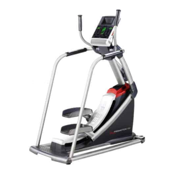
Model No. SFSR71709.2
Serial No.
Write the serial number in the space
above for reference.
QUESTIONS?
If you have questions, or if parts
are damaged or missing, DO NOT
CONTACT THE STORE; please
contact Customer Care.
IMPORTANT: Please register this
product (see the limited warranty
on the back cover of this manual)
before contacting Customer Care.
CALL TOLL-FREE:
1-800-999-3756
Mon.––Fri. 6 a.m.––6 p.m. MT
Sat. 8 a.m.––4 p.m. MT
ON THE WEB:
www.iconservice.com
CAUTION
Read all precautions and instruc-
tions in this manual before using
this equipment. Keep this manual
for future reference.
Serial
Number
Decal
USER’'S MANUAL
Advertisement
Table of Contents


Need help?
Do you have a question about the SFSR71709.2 and is the answer not in the manual?
Questions and answers
I can’t find where to plug into the machine
Plug the power adapter into the jack on the front of the strider. Then plug the adapter into an outlet.
This answer is automatically generated
How do I clean the tracks.
To clean the tracks on a Freemotion SFSR71709.2, use a damp cloth and a small amount of mild soap. Regularly clean the track rollers and the track frame on which the track rollers ride. Avoid liquids near the console to prevent damage.
This answer is automatically generated