Table of Contents
Advertisement
Advertisement
Table of Contents
Troubleshooting

Related Manuals for Advance acoustic Terra 4300B


Summary of Contents for Advance acoustic Terra 4300B
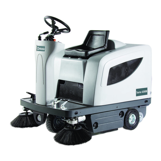
- Page 1 Terra 4300B SERVICE MANUAL Advance model: 908 4309 010 1463200000(2)2008-07...
-
Page 3: Table Of Contents
SERVICE MANUAL ENGLISH INDEX INDEX GENERAL INFORMATION ............................3 MACHINE LIFTING ............................... 3 MACHINE TRANSPORTATION ..........................3 PUSHING OR TOWING THE MACHINE ......................3 OTHER REFERENCE MANUALS AVAILABLE ..................... 3 SAFETY ................................3 GENERAL SAFETY PRECAUTIONS ........................4 TECHNICAL DATA ..............................6 MAINTENANCE .............................. - Page 4 ENGLISH SERVICE MANUAL INDEX DUST AND DEBRIS COLLECTION SYSTEM ......................37 DUST FILTER CLEANING AND INTEGRITY CHECK ..................37 FILTER SHAKER OPERATION CHECK ......................39 FILTER SHAKER MOTOR DISASSEMBLY/REASSEMBLY ................39 VACUUM FAN DISASSEMBLY/REASSEMBLY [till S/N 072820295] .............................. 40 POWER VACUUM FAN DISASSEMBLY/REASSEMBLY [starting from S/N 072820296] ..........................
-
Page 5: General Information
SERVICE MANUAL ENGLISH GENERAL INFORMATION GENERAL INFORMATION CONVENTIONS Front, rear, right or left indications in this manual are intended with reference to the operator’s driver’s seat position. MACHINE LIFTING WARNING! Do not work under the lifted machine without supporting it with safety stands. MACHINE TRANSPORTATION WARNING! Before transporting the machine, make sure that:... -
Page 6: General Safety Precautions
ENGLISH SERVICE MANUAL GENERAL INFORMATION GENERAL SAFETY PRECAUTIONS Specific warnings and cautions used to indicate potential damage to people and machines are shown below. DANGER! – Before performing any maintenance, repair, cleaning or replacement procedure disconnect the battery connector, remove the ignition key and engage the parking brake. –... - Page 7 SERVICE MANUAL ENGLISH GENERAL INFORMATION WARNING! – Carefully read all the instructions before performing any maintenance/repair procedure. – Take all necessary precautions to prevent hair, jewels and loose clothes from being caught by the machine moving parts. – For machines with electronic battery charger (optional): –...
-
Page 8: Technical Data
ENGLISH SERVICE MANUAL GENERAL INFORMATION TECHNICAL DATA Dimensions and weights Values Machine length 58.3 in (1480 mm) Machine width (with two side brooms) 47.2 in (1200 mm) Machine maximum height (at the steering wheel) 48.0 in (1220 mm) Cleaning width (without side brooms) 27.6 in (700 mm) Cleaning width with two side broom 49.6 in (1260 mm) -
Page 9: Service Manual
SERVICE MANUAL ENGLISH GENERAL INFORMATION TECHNICAL DATA (continues) Performance data Values Max forward speed 3.7 mph (6 Km/h) Maximum reverse speed 1.8 mph (3 Km/h) Gradeability at full load Main broom rotation speed 550 rpm Side broom rotation speed 80 rpm Panel filter area 14.1 ft (4,3 m... - Page 10 ENGLISH SERVICE MANUAL GENERAL INFORMATION DIMENSIONS 1480 mm (58.3 in) S301231 146 2889 000(2)2007-08 Terra 4300B...
-
Page 11: Maintenance
SERVICE MANUAL ENGLISH GENERAL INFORMATION MAINTENANCE SCHEDULED MAINTENANCE The lifespan of the machine and its maximum operating safety are ensured by correct and regular maintenance. NOTE See GENERAL INFORMATION and SAFETY - ACCIDENT PREVENTION The following table provides the scheduled maintenance. The intervals shown may vary according to particular working conditions, which are to be defined by the person in charge of the maintenance. -
Page 12: Machine Nomenclature
ENGLISH SERVICE MANUAL GENERAL INFORMATION MACHINE NOMENCLATURE Throughout this manual you will find numbers in brackets – for example: (2). These numbers refer to the components indicated in these two nomenclature pages. Refer to these pages whenever it will be necessary to identify a component mentioned in the text. Left control panel Battery connection diagrams Ignition key... - Page 13 SERVICE MANUAL ENGLISH GENERAL INFORMATION MACHINE NOMENCLATURE S301231 Terra 4300B 146 2889 000(2)2007-08...
- Page 14 ENGLISH SERVICE MANUAL GENERAL INFORMATION MACHINE NOMENCLATURE S301232 146 2889 000(2)2007-08 Terra 4300B...
-
Page 15: Sweeping System
SERVICE MANUAL ENGLISH SWEEPING SYSTEM SWEEPING SYSTEM MAIN BROOM HEIGHT CHECK AND ADJUSTMENT NOTE Brooms of various hardness are available. This procedure is applicable to all types of brooms. Check the main broom for proper ground clearance, proceeding as follows: •... -
Page 16: Side Broom Height Check And Adjustment
ENGLISH SERVICE MANUAL SWEEPING SYSTEM MAIN BROOM DISASSEMBLY/REASSEMBLY NOTE Brooms of various hardness are available. This procedure is applicable to all types of brooms. CAUTION! It is advisable to use protective gloves when replacing the main broom because there can be cutting debris between the bristles. - Page 17 SERVICE MANUAL ENGLISH SWEEPING SYSTEM SIDE BROOM HEIGHT CHECK AND ADJUSTMENT NOTE Brooms of various hardness are available. This procedure is applicable to all types of brooms. Check Check the side brooms for proper ground clearance, proceeding as follows: • Drive the machine on a level ground and lower the side brooms.
-
Page 18: Side Broom Disassembly/Reassembly
ENGLISH SERVICE MANUAL SWEEPING SYSTEM SIDE BROOM DISASSEMBLY/REASSEMBLY NOTE Brooms of various hardness are available. This procedure is applicable to all types of brooms. CAUTION! It is advisable to use protective gloves when replacing the side brooms, because there can be cutting debris between the bristles. -
Page 19: Side Broom Lifting Cable Disassembly/Reassembly
SERVICE MANUAL ENGLISH SWEEPING SYSTEM SIDE BROOM LIFTING CABLE DISASSEMBLY/REASSEMBLY Disassembly Drive the machine onto an appropriate lifting hook. Engage the parking brake (20 and 21). Turn the ignition key (2) to “0” position. Operating according to the safety rules, lift the machine. If the lifting hook is not available, engage the machine to the four anchors (56), and lift it with a proper hoisting system, operating according to the safety rules. -
Page 20: Main Broom Driving Belt Visual Inspection
ENGLISH SERVICE MANUAL SWEEPING SYSTEM MAIN BROOM DRIVING BELT VISUAL INSPECTION Drive the machine on a level ground and engage the parking brake (20 and 21). Turn the ignition key (2) to “0” position. Unscrew the knobs (38) and remove the left door (37). Visually inspect the belt (A) for integrity, cracks or breaks, along its whole length;... -
Page 21: Main Broom Driving Belt Disassembly/Reassembly
SERVICE MANUAL ENGLISH SWEEPING SYSTEM MAIN BROOM DRIVING BELT DISASSEMBLY/REASSEMBLY Disassembly Drive the machine on a level ground and engage the parking brake (20 and 21). Turn the ignition key (2) to “0” position. Lower the main broom with the lever (16). With a wrench on the screw (A) rotate the pulley (B) clockwise, and disengage the belt (C) from the pulley. -
Page 22: Main Broom Gas Spring Disassembly/Reassembly
ENGLISH SERVICE MANUAL SWEEPING SYSTEM MAIN BROOM GAS SPRING DISASSEMBLY/REASSEMBLY Disassembly Remove the main broom. Unscrew the knobs (38) and remove the left door (37). Lower the main broom with the lever (16). Open the hood (24) with a handle (55). Unscrew the main broom height adjustment knobs (A and B) completely. -
Page 23: Main Broom Pulley Bearing Replacement
SERVICE MANUAL ENGLISH SWEEPING SYSTEM MAIN BROOM PULLEY BEARING REPLACEMENT Disassembly Drive the machine onto an appropriate lifting hook. Engage the parking brake (20 and 21). Turn the ignition key (2) to “0” position. Operating according to the safety rules, lift the machine. If the lifting hook is not available, engage the machine to the four anchors (56), and lift it with a proper hoisting system, operating according to the safety rules. -
Page 24: Main Broom Motor Electrical Input Check
ENGLISH SERVICE MANUAL SWEEPING SYSTEM MAIN BROOM MOTOR ELECTRICAL INPUT CHECK WARNING! This procedure must be performed by qualified personnel only. Remove the main broom (see the procedure in the relevant paragraph). Lift the hood (24) with a handle (55). WARNING! Pay attention to the moving parts while performing the following steps. -
Page 25: Main Broom Motor Carbon Brush Check And Replacement
SERVICE MANUAL ENGLISH SWEEPING SYSTEM MAIN BROOM MOTOR CARBON BRUSH CHECK AND REPLACEMENT Check Remove the main broom motor (see the procedure in the relevant paragraph). Remove the nuts (A) and the cover (B) at the cabinet bench. Remove dust and dirt from the motor exterior part; then disengage and remove the clamp (C). Lift the retaining spring (D) of each carbon brush, then remove the four carbon brushes (E). -
Page 26: Main Broom Motor Disassembly/Reassembly
ENGLISH SERVICE MANUAL SWEEPING SYSTEM MAIN BROOM MOTOR DISASSEMBLY/REASSEMBLY Disassembly Remove the main broom driving belt (see the procedure in the relevant paragraph). Disconnect the main broom motor (B) electrical connection (A). Remove the motor fastening screws (C). Remove the main broom motor (B). Reassembly Reassemble in the reverse order of disassembly. -
Page 27: Side Broom Motor Electrical Input Check
SERVICE MANUAL ENGLISH SWEEPING SYSTEM SIDE BROOM MOTOR ELECTRICAL INPUT CHECK NOTE This procedure refers to the right broom: The procedure for the left broom is the same. WARNING! This procedure must be performed by qualified personnel only. Remove the side broom of the motor to be checked (see the procedure in the relevant paragraph). WARNING! Pay attention to the brooms and the moving parts while performing the following steps. -
Page 28: Side Broom Motor Carbon Brush Check And Replacement
ENGLISH SERVICE MANUAL SWEEPING SYSTEM SIDE BROOM MOTOR CARBON BRUSH CHECK AND REPLACEMENT Check Remove the motor of the side broom to be checked (see the procedure in the relevant paragraph). At the cabinet bench, clean the outside of the motor from dirt and dust, then mark the reciprocal position (A) between the cover (B) and the motor body (C). -
Page 29: Side Broom Motor Disassembly/Reassembly
SERVICE MANUAL ENGLISH SWEEPING SYSTEM SIDE BROOM MOTOR DISASSEMBLY/REASSEMBLY NOTE This procedure refers to the right broom: The procedure for the left broom is the same. Disassembly Remove the side broom of the motor to be checked (see the procedure in the relevant paragraph). Disconnect the side broom motor electrical connection (D). -
Page 30: Side Broom Activation Microswitch Adjustment And Disassembly/Reassembly
ENGLISH SERVICE MANUAL SWEEPING SYSTEM SIDE BROOM ACTIVATION MICROSWITCH ADJUSTMENT AND DISASSEMBLY/REASSEMBLY Preliminary operations Remove the front cover (see the procedure in the relevant paragraph). Adjustment Lift the side brooms with the lever (15), then check that the distance between the microswitch actuator (A) and the activation joint (B) is of 2 -3 mm. -
Page 31: Main Broom Activation Microswitch Adjustment And Disassembly/Reassembly
SERVICE MANUAL ENGLISH SWEEPING SYSTEM MAIN BROOM ACTIVATION MICROSWITCH ADJUSTMENT AND DISASSEMBLY/REASSEMBLY Preliminary operations Remove the front cover (see the procedure in the relevant paragraph). Adjustment Lift the main broom with the lever (16), then check that the distance between the microswitch actuator (A) and the activation joint (B) is of 2 -3 mm. -
Page 32: Troubleshooting
ENGLISH SERVICE MANUAL SWEEPING SYSTEM TROUBLESHOOTING OPEN CIRCUIT The thermal fuses (68) and (69) determine the open circuit. This system allows to prevent the broom circuits and motors from being damaged under overload conditions. If there is an open in the electrical circuit, the possible causes are the following. Main broom motor;... -
Page 33: Skirt
SERVICE MANUAL ENGLISH SKIRT SKIRT SKIRT HEIGHT AND OPERATION CHECK AND ADJUSTMENT Drive the machine on a level and adequate ground to check the skirt height. Engage the parking brake (20 and 21). Turn the ignition key (2) to “0” position. Side skirt check Unscrew the knobs (40 and 38) and remove both left and right doors (39 and 37). - Page 34 ENGLISH SERVICE MANUAL SKIRT SKIRT HEIGHT AND OPERATION CHECK AND ADJUSTMENT (continues) S301260 S301261 S301262 S301263 146 2889 000(2)2007-08 Terra 4300B...
-
Page 35: Side Skirt Disassembly/Reassembly
SERVICE MANUAL ENGLISH SKIRT SIDE SKIRT DISASSEMBLY/REASSEMBLY Disassembly Drive the machine on a level ground that is suitable for checking the skirt height. Engage the parking brake (20 and 21). Turn the ignition key (2) to “0” position. Unscrew the knobs (40 and 38) and remove both left and right doors (39 and 37). Remove the screws (A), the strap (B), the right and left side skirts (C). -
Page 36: Rear Skirt Disassembly/Reassembly
ENGLISH SERVICE MANUAL SKIRT REAR SKIRT DISASSEMBLY/REASSEMBLY Disassembly Drive the machine on a level ground that is suitable for checking the skirt height. Remove the main broom (see the procedure in the relevant paragraph). Remove the screws (A) the straps (B) and the rear skirt (C). Reassembly Assemble the rear skirt (C) with the strap (B) and the screws (A). -
Page 37: Front Skirt Disassembly/Reassembly
SERVICE MANUAL ENGLISH SKIRT FRONT SKIRT DISASSEMBLY/REASSEMBLY Disassembly Drive the machine on a level ground that is suitable for checking the skirt height. Engage the parking brake (20 and 21). Turn the ignition key (2) to “0” position. Remove the left side broom (28) (if present) (see the procedure in the relevant paragraph). Operating on the left front side of the front skirt, disengage the spring (A) from the side (B). -
Page 38: Front Skirt Lifting Cable Disassembly/Reassembly
ENGLISH SERVICE MANUAL SKIRT FRONT SKIRT LIFTING CABLE DISASSEMBLY/REASSEMBLY Disassembly Drive the machine on a level ground that is suitable for checking the skirt height. Engage the parking brake by means of the pedal and the lever (20 and 21). Turn the ignition key (2) to “0”... -
Page 39: Dust And Debris Collection System
SERVICE MANUAL ENGLISH DUST AND DEBRIS COLLECTION SYSTEM DUST AND DEBRIS COLLECTION SYSTEM DUST FILTER CLEANING AND INTEGRITY CHECK NOTE Besides the standard paper filter, optional polyester filters are also available. The following procedure is applicable to each type of filter. Drive the machine on a level ground and engage the parking brake (20 and 21). - Page 40 ENGLISH SERVICE MANUAL DUST AND DEBRIS COLLECTION SYSTEM DUST FILTER CLEANING AND INTEGRITY CHECK (continues) S301272 S301273 146 2889 000(2)2007-08 Terra 4300B...
-
Page 41: Filter Shaker Operation Check
SERVICE MANUAL ENGLISH DUST AND DEBRIS COLLECTION SYSTEM FILTER SHAKER OPERATION CHECK During machine operation, when the panel filter is supposed to be clogged, press the switch (9) onwards for a few seconds to activate the filter shaker motor and check that the related noise is audible. Restart machine operation and check if the filter has been shaken. -
Page 42: Vacuum Fan Disassembly/Reassembly [Till S/N 072820295]
ENGLISH SERVICE MANUAL DUST AND DEBRIS COLLECTION SYSTEM VACUUM FAN DISASSEMBLY/REASSEMBLY (till S/N 072820295) Disassembly Drive the machine on a level ground and engage the parking brake (20 and 21). Turn the ignition key (2) to “0” position. Unplug the battery connector (62). Disengage the hook (35) by pulling its lower end. -
Page 43: Power Vacuum Fan Disassembly/Reassembly [Starting From S/N 072820296]
SERVICE MANUAL ENGLISH DUST AND DEBRIS COLLECTION SYSTEM POWER VACUUM FAN DISASSEMBLY/REASSEMBLY (starting from S/N 072820296) Disassembly Drive the machine on a level ground and engage the parking brake (20 and 21). Turn the ignition key (2) to “0” position. Unplug the battery connector (62) Disengage the hook (35) by pulling its lower end. -
Page 44: Troubleshooting
ENGLISH SERVICE MANUAL DUST AND DEBRIS COLLECTION SYSTEM TROUBLESHOOTING POOR OPERATION OF THE VACUUM FAN Possible causes: The dust filter is obstructed (clean). Vacuum fan with broken/worn fins (replace the vacuum fan). Worn waste container gaskets (replace). THE FILTER SHAKER MOTOR DOES NOT OPERATE Possible causes: Faulty motor (repair or replace). -
Page 45: Steering And Braking System
SERVICE MANUAL ENGLISH STEERING AND BRAKING SYSTEM STEERING AND BRAKING SYSTEM STEERING CHAIN CHECK AND CLEANING NOTE The steering chain is not adjustable. Drive the machine on a level ground and engage the parking brake (20 and 21). Turn the ignition key (2) to “0” position. Remove the left side broom, if present (see the procedure in the relevant paragraph). -
Page 46: Steering Chain Disassembly/Reassembly
ENGLISH SERVICE MANUAL STEERING AND BRAKING SYSTEM STEERING CHAIN DISASSEMBLY/REASSEMBLY NOTE The steering chain is not adjustable. Disassembly Drive the machine on a level ground and engage the parking brake (20 and 21). Turn the ignition key (2) to “0” position. By turning the steering wheel, take the steering chain (B) junction link (A) at an accessible position. -
Page 47: Service And Parking Brake Check And Adjustment
SERVICE MANUAL ENGLISH STEERING AND BRAKING SYSTEM SERVICE AND PARKING BRAKE CHECK AND ADJUSTMENT Drive the machine on a level ground. Do not engage the parking brake (20 and 21), but check that the machine cannot move independently. Turn the ignition key (2) to “0” position. Turn the front wheel (A) to the left. -
Page 48: Brake Control Cable Replacement
ENGLISH SERVICE MANUAL STEERING AND BRAKING SYSTEM BRAKE CONTROL CABLE REPLACEMENT Disassembly Drive the machine on a level ground. Do not engage the parking brake (20 and 21), but check that the machine cannot move independently. Turn the ignition key (2) to “0” position. Remove the cap (A) from the brake control cable (B). -
Page 49: Brake System Disassembly/Reassembly
SERVICE MANUAL ENGLISH STEERING AND BRAKING SYSTEM BRAKE SYSTEM DISASSEMBLY/REASSEMBLY Disassembly Drive the machine on a level ground. Do not engage the parking brake (20 and 21), but check that the machine cannot move independently, by applying wedges to the rear wheels. Turn the ignition key (2) to “0”... -
Page 50: Drive System
ENGLISH SERVICE MANUAL DRIVE SYSTEM DRIVE SYSTEM DRIVE MOTOR ELECTRICAL INPUT CHECK WARNING! This procedure must be performed by qualified personnel only. Drive the machine on a level ground. Engage the parking brake (20 and 21). Turn the ignition key (2) to “0” position. With a proper and safe hoisting system, hook the machine on the two front lifting anchors (56), then lift it until the rear wheels (25) are at 4-5 cm from the ground. -
Page 51: Drive Motor Carbon Brush Check And Replacement
SERVICE MANUAL ENGLISH DRIVE SYSTEM DRIVE MOTOR CARBON BRUSH CHECK AND REPLACEMENT Check Remove the drive system (see the procedure in the relevant paragraph). Remove the nuts (A) and the cover (B) at the cabinet bench. Remove dust and dirt from the motor exterior part; then disengage and remove the clamp (C). Lift the retaining spring (D) of each carbon brush, then remove the four carbon brushes (E). -
Page 52: Drive System Disassembly/Reassembly
ENGLISH SERVICE MANUAL DRIVE SYSTEM DRIVE SYSTEM DISASSEMBLY/REASSEMBLY Disassembly Drive the machine on a level ground and engage the parking brake (20 and 21). Turn the ignition key (2) to “0” position. Unscrew the knobs (38) and remove the left door (37). Unscrew the knobs (40) and remove the right door (39). -
Page 53: Drive Motor Disassembly/Reassembly
SERVICE MANUAL ENGLISH DRIVE SYSTEM DRIVE MOTOR DISASSEMBLY/REASSEMBLY Disassembly Remove the drive system (see the procedure in the relevant paragraph). At the cabinet bench, remove the screws (A) and the wheels (B), then recover the keys and the washers. Remove the screws (D), (E) and (J). Loosen the threaded dowels (F). -
Page 54: Forward/Reverse Gear Pedal Disassembly/Reassembly
ENGLISH SERVICE MANUAL DRIVE SYSTEM FORWARD/REVERSE GEAR PEDAL DISASSEMBLY/REASSEMBLY Disassembly Drive the machine on a level ground. Engage the parking brake (20 and 21). Remove the pedal fastening screws (A). Slightly lift the pedal (B) and disconnect the electrical connector (C). Reassembly Reassemble in the reverse order of disassembly. -
Page 55: Forward/Reverse Gear Pedal Potentiometer Check And Adjustment
SERVICE MANUAL ENGLISH DRIVE SYSTEM FORWARD/REVERSE GEAR PEDAL POTENTIOMETER CHECK AND ADJUSTMENT Remove the forward/reverse gear pedal (see the procedure in the relevant paragraph). At the cabinet bench, remove the screws (A) and the guard (B). Apply the tester on the central contact (C) and on a side contact (D) of the connector; then check that the resistance is between 2,500 ±... -
Page 56: Troubleshooting
ENGLISH SERVICE MANUAL DRIVE SYSTEM TROUBLESHOOTING THE MACHINE DOES NOT MOVE The possible causes can be: Worn motor carbon brushes (replace). Faulty motor (repair or replace). Broken running consent under-seat switch (replace). Misadjusted or broken forward/reverse gear pedal potentiometric accelerator (adjust or replace). Activated brake (deactivate) Broken drive electronic board (replace). -
Page 57: Table Of Drive Board Error Codes
SERVICE MANUAL ENGLISH DRIVE SYSTEM TABLE OF ERROR CODES SIGNALLED BY THE DRIVE BOARD LED LED CODES ERROR DESCRIPTION (REMEDY) Notes Reference LED flashing type LED off Control system malfunction, or drive fuse (FT) blown, or seat microswitch activated, or electrical cable disconnected (check the drive board wire harness) LED on Control system operating, no malfunctions detected... -
Page 58: Other Systems
ENGLISH SERVICE MANUAL OTHER SYSTEMS OTHER SYSTEMS SCREW AND NUT TIGHTENING CHECK Drive the machine on a level ground and engage the parking brake by means of the pedal and the lever (20 and 21). Turn the ignition key (2) to “0” position. Open the hood (24) with a handle (55). -
Page 59: Front Cover Disassembly/Reassembly
SERVICE MANUAL ENGLISH OTHER SYSTEMS FRONT COVER DISASSEMBLY/REASSEMBLY Disassembly Drive the machine on a level ground and engage the parking brake by means of the pedal and the lever (20 and 21). Turn the ignition key (2) to “0” position. Remove the cap (A). - Page 60 ENGLISH SERVICE MANUAL OTHER SYSTEMS FRONT COVER DISASSEMBLY/REASSEMBLY (continues) S301298 S301299 S301300 146 2889 000(2)2007-08 Terra 4300B...
-
Page 61: Seat Running Consent Microswitch Disassembly/Reassembly
SERVICE MANUAL ENGLISH OTHER SYSTEMS SEAT RUNNING CONSENT MICROSWITCH DISASSEMBLY/REASSEMBLY Disassembly Drive the machine on a level ground and engage the parking brake (20 and 21). Turn the ignition key (2) to “0” position. Open the hood (24) with a handle (55). Operating inside the hood, disconnect the seat microswitch electrical connector (A). -
Page 62: Electrical System
ENGLISH SERVICE MANUAL ELECTRICAL SYSTEM ELECTRICAL SYSTEM BATTERY CHARGING See User Manual. FUSE REPLACEMENT Drive the machine on a level ground and engage the parking brake (20 and 21). Turn the ignition key (2) to “0” position. Open the hood (24) with a handle (55). Remove the box (67) cover and the concerned lamellar fuse among the following fuses: •... -
Page 63: Troubleshooting
SERVICE MANUAL ENGLISH ELECTRICAL SYSTEM TROUBLESHOOTING See the previous chapters related to the use of the electrical system. Other possible causes: Discharged battery or not-efficient connections (charge the battery or clean the connections). Blown fuses (replace). Faulty battery electrical connector/terminals (replace). Cut or shorted to ground wire harness (repair). - Page 64 ENGLISH SERVICE MANUAL ELECTRICAL SYSTEM COMPONENT LOCATION (continues) S301309 146 2889 000(2)2007-08 Terra 4300B...
- Page 65 SERVICE MANUAL ENGLISH ELECTRICAL SYSTEM COMPONENT LOCATION (continues) S301310 Terra 4300B 146 2889 000(2)2007-08...
- Page 66 ENGLISH SERVICE MANUAL ELECTRICAL SYSTEM SCHEMA ELETTRICO Legenda Colour codes Batteries Black Pivoting light (optional) Blue Reverse gear warning buzzer Brown Battery connector Green Battery charger secondary connector (optional) Grey Battery charger (optional) Orange Hour counter and battery voltage display Pink Drive electronic board Main broom relay...
-
Page 67: Wiring Diagram
SERVICE MANUAL ENGLISH ELECTRICAL SYSTEM WIRING DIAGRAM (continues) S301313 Terra 4300B 146 2889 000(2)2007-08... - Page 68 Nilfisk-Advance, Inc. 14600 21st Avenue North Plymouth, MN, 55447-3408 www.nilfisk-advance.com Phone: 800-989-2235 Fax: 800-989-6566 ©2008 Nilfisk-Advance, Inc., Plymouth, MN 55447-3408 Printed in Italy...
Need help?
Do you have a question about the Terra 4300B and is the answer not in the manual?
Questions and answers