FrontRow JUNO User Manual
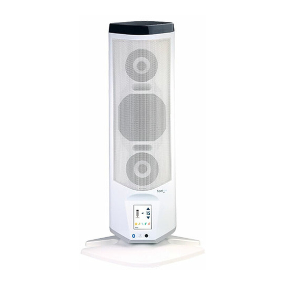
Itr-01 tower receiver/ itm-01 pendant microphone/ ism-01 pass-around microphone/ imc-01 microphone charger
Hide thumbs
Also See for JUNO:
- Configuration manual (29 pages) ,
- Quick start manual (9 pages) ,
- Quick setup manual (2 pages)

Related Manuals for FrontRow JUNO


Summary of Contents for FrontRow JUNO
- Page 1 user guide ITR-01 Tower Receiver ITM-01 Pendant Microphone ISM-01 Pass-Around Microphone IMC-01 Microphone Charger...
-
Page 2: Table Of Contents
ITR-01 Juno Tower Receiver ........ -
Page 3: Important Safety Instructions
important safety instructions 1. Read these instructions. 13. Unplug this apparatus during lightning storms or when unused for long periods 2. Keep these instructions. of time. 3. Heed all warnings. 14. Refer all servicing to qualified service personnel. Servicing is required when 4. -
Page 4: Electrical Warnings
DO NOT disassemble the power supply. PRECAUTIONS & SAFETY Return the apparatus to FrontRow for RECOMMENDATIONS qualified service and repair if required. Incorrect reassembly may result in a risk of Follow Manufacturers' Recommendations electric shock or fire. -
Page 5: System Contents, Optional Components & Expansion Modules
Contents ITM-01 Pendant Lithium Ion Microphone Battery Aux-in cord 1 meter micro USB cable Phillips head ITR-01 Juno Tower Wall mounting Amplifier / Receiver screwdriver screw set Power supply 4 meter USB cable User guide AC cable Optional components... -
Page 6: Setup And Placement
(e.g. DVD player) You can either mount the Juno Tower on a wall using a standard 100mm VESA mount (recommended) or simply place it on a table using the stand provided. In any case, the bottom edge of the Tower should be at least 4.5 feet (1.3m) from the floor. -
Page 7: Volume Setting
Volume setting guidance Your Juno Tower is equipped with a powerful feedback suppression engine that helps avoid harsh squealing noise that would normally occur when a microphone gets too close to a speaker. Nevertheless, try to use volume settings for daily use that give good audibility without constantly activating the feedback suppression engine. -
Page 8: Features
(behind main cover) Integrated high sensitivity infrared diode array Add the optional Channel Expansion Module to covers a typical classroom without the need for use up to five microphones with the Juno Tower. additional sensors. Wall Mount screw Taps 2.1 speaker Array 100mm VESA mount compliant. - Page 9 Using the included USB cable, connect to a computer running the FrontRow Desktop software application for remote control of the Juno Tower. NOTE: A 4-meter USB cable is included with your Juno System. Maximum cable length recommended is 5 meters.
-
Page 10: Itm01 Pendant Microphone
Microphone. Use with voice command ™ to activate the Echo lesson capture software and control your Juno Tower. When the Pendant Microphone is in standby mode: PRESS MOMENTARILY ..Awaken 7 Lithium ion Battery... -
Page 11: Ism-01 Pass-Around Microphone
73.7g/2.6oz the Pass-Around, microphone is much easier for even young students to For charging via USB cable or for use than a standard-sized microphone. configuring settings using the FrontRow Desktop software application. 6 Power/Push-to-talk switch 10 Portable Audio interface The push-to-talk option makes transitions when passing the microphone between 3.5mm audio input jack lets you use the... -
Page 12: Activate Tower And Microphone
Activate Tower and Microphone Image 3 1. Turn Tower on. See Image 3 2. Place microphone around neck and connect clasp. 3. Adjust neck straps to position microphone Power approximately 5in (14cm) from mouth. switch See Image 4 4. Press One-Touch button to wake micro- phone. -
Page 13: Tower Controls
Home Screen Master Volume Up (press and hold to increase volume quickly) Master Mute Master Volume Down (press and hold to decrease volume quickly) Room 10 Name of Tower (set via FrontRow Desktop software) Settings Device Microphone Volume Menu Volume Menu... - Page 14 Room 10 Device Volume You can control the individual volume of each device connected to your Juno Tower. Devices that are currently playing audio will appear in white text and have a green check mark in the far right on the orange bar.
- Page 15 NOTE: A Juno system comes standard with the ability to use two microphones simultaneously. With the optional Channel Expansion Module your Juno system can be used with up to five microphones simultaneously. NOTE: When playing music from a device connected to the Microphone's Audio-in jack,...
-
Page 16: Settings
Image 11 From the Settings Menu, you can customize some of your Juno Tower's available features. See Image 11 1. Select the feature you would like to configure. 2. See details for each feature below. NOTE: Additional settings are available through the FrontRow Desktop software application. -
Page 17: Prioriteach
™ PrioriTeach Image 13 Use PrioriTeach to have the Juno Tower automatically reduce the volume of all other audio sources including Pass-Around Microphones when you speak into the Pendant Microphone. See Image 13 NOTE: Advanced settings for PrioriTeach are available through the optional FrontRow Desktop software. -
Page 18: Speaker Balancing
Use the Speaker Balancing option to adjust the balance between the Tower’s internal speakers and the external speakers. See Image 15 Restore Defaults Image 16 Your Juno Tower can be restored to factory defaults if necessary. See Image 16... -
Page 19: About
Locking the LCD Image 18 To prevent tampering with settings, the LCD on your Juno Tower can be locked using a voice command or the optional FrontRow Desktop software. To lock or unlock your Tower LCD using Voice Command, say “LCD”. -
Page 20: Lcd Calibration
LCd Calibration Touch Screen Calibration Image 19 Although unlikely, the Juno Tower's touch screen may drift out of alignment over time. If it does not respond accurately when you touch it, it will need to be calibrated. Calibrating Touch Screen 1. -
Page 21: Voice Command
Voice Command Your Juno System includes a voice command feature that lets you remotely control parameters of your Juno Tower using a few simple voice commands. To issue a voice command: 1. Press and hold the One-Touch button on the Pendant Microphone. -
Page 22: Lesson Capture Through Echo
Connect the Juno Tower to your computer 1. Plug a 3.5mm cord into the Audio Out port on the side of the Juno Tower and connect the other end to the line-in or mic-in input on your computer. See Image 20 2. -
Page 23: Collaborative Learning Using Class 2 Class
Use the Juno Tower to ensure all students are able to effectively participate in the learning session by easily hearing the conversation as well as sharing their thoughts during the session using the optional Pass-Around Microphones. -
Page 24: Connecting To Other Classroom Media
Connecting to other Classroom Media Your FrontRow Juno System can connect to other media to enhance the overall audio experience in your classroom. Ideally, these connections were made during installation; however, they can easily be made after the unit is installed using standard audio cords from your local electronics store. - Page 25 Example 2 If your classroom does not have an EZRoom AV Control System, you can connect your computer directly to your Juno Tower. This can be done using your computer’s headphone jack connected to one of the three stereo RCA inputs.
- Page 26 Example 3 Some classrooms use the TV/DVD/VCR as stand-alone media. For these classrooms, you may need to use two auxiliary audio input connections to the Juno Tower. DVD Player Audio In Audio Video Audio Out Internet Computer...
- Page 27 To amplify audio from portable electronics, it may be most convenient to connect these as needed through the quick connect jack on the front of the Juno Tower. Turn the volume on the MP3 player at least 3/4 of the way up for best sound quality.
- Page 28 Plug the other end of the adaptor cord to the Audio In jack on the Microphone. See Image 25 2. On the Juno Tower LCD, check the "Music Audio in" box on the Microphone's Volume Setting screen.
-
Page 29: Rebroadcasting To Personal Fm Receivers
rebroadcasting via Personal FM receivers Image 22 Allows rebroadcast of all voice and auxiliary audio directly to a hearing-impaired student's personal FM system. 1. Turn on the student's personal FM trans- mitter. Press the transmitter's mic mute switch for best results. 2. -
Page 30: Itm-01 Pendant Microphone
iTM-01 Pendant Microphone using Image 23 1. Place microphone around neck and connect clasp. 2. Adjust neck straps to position microphone approximately 5in (14cm) from mouth. See Image 23 3. Press One-Touch button to wake microphone. 5in/14cm Power indicator should be green. See Image 24 NOTE: Your microphone will go into standby mode (off) automatically after 10 minutes in... -
Page 31: Battery
Battery Image 25 Installing the battery 1. Unscrew battery door on the back of the microphone using the supplied Phillips screwdriver. See Image 25 2. Locate the charge contacts on the battery and on the microphone. See Image 26 3. Insert battery into compartment - battery contacts first, then push the battery into place. -
Page 32: Charging
Charge your battery in one of four ways: • IMC-01 universal microphone charger (optional). See Image 28 • USB cable connected to one of your Juno Tower’s charge ports. See Image 29 • USB cable connected to your computer’s USB port*. See Image 30 •... -
Page 33: Ism-01 Pass-Around Microphone
isM-01 Pass-Around Microphone using Image 32 1. Turn microphone on by sliding the Power Switch up. See Image 32 2. Note Power Indicator (chair icon). Emitter diodes See Image 32 Power indicator Green = On and transmitting Off = Power is off Power/ NOTE: In order to conserve battery life, if Push-to-talk... -
Page 34: Labeling
Labeling Image 35 Your Pass-Around Microphone includes a location for adding a name or room number clear window for easy identification. 1. Place the Microphone on a stable surface with the battery door facing up. 2. Remove the battery door using the supplied Phillips screwdriver. -
Page 35: Battery
Battery Image 36 Installing the battery 1. Unscrew battery door on the back of the microphone using the supplied Phillips head screwdriver. See Image 36 2. Locate the charge contacts on the battery and on the microphone. See Image 37 3. -
Page 36: Charging
Charge your microphone in one of four ways: • IMC-01 universal microphone charger (optional). See Image 39 • USB cable connected to one of your Juno Tower’s charge ports. See Image 40 • USB cable connected to your computer’s USB port *. See Image 41 •... -
Page 37: Microphone Configuration
Microphone Configuration Your microphones can be configured using the FrontRow Desktop application*. Microphone name – You can name your microphone for display on the Juno Tower LCD screen, making it easier to identify when changing volume. Channel assignment – Assign the operating channels for your microphone. -
Page 38: Using Multiple Microphones
Position Position *The Juno Tower comes standard with 2 channels. Add 3 additional channels with the optional Channel Expansion Module. ** If you do not have the FrontRow Desktop software installed, a free Microphone Settings application is available at gofrontrow.com/products/frontrow-juno. - Page 39 6. Unscrew battery door using the supplied Image 44 Phillips screwdriver. See Image 44 7. Using the channel indicator labels included with your microphones, label the switch Pendant Microphone positions you've just reprogrammed. See Image 45 8. Move the selection switch (see Image 46) to the channel you want to use –...
-
Page 40: Imc-01 Microphone Charger
iMC-01 Microphone Charger Image 47 Charger setup 1. Insert microphones in either of the two charge pockets. See Image 47 2. Find the power plug that is appropriate for the power outlet style in your country. See Image 48 3. Slide power plug onto the power supply. See Image 49 4. -
Page 41: Troubleshooting
Tower is not recognized by my computer firmware update, open the Microphone Settings application and connect the • Verify that you have the Juno Tower drivers microphone to the computer with the USB installed. To install the drivers, you will need cable. - Page 42 • Your device may be emitting a low level • If reception is interrupted or noisy when fac- hum that is amplified by the Juno Tower. ing a certain direction, install an additional Use a filtering cable such as a ground loop...
-
Page 43: Regulatory
FCC notes dispose of your waste at your local waste site The Juno system is approved by the FCC or it is collected from your home. Please con- (Federal Communications commission). tact your local authority for further information. - Page 44 © 2012 FrontRow Calypso LLC Phonic Ear, FrontRow, Calypso and the names of Phonic Ear, Calypso, and FrontRow products are trademarks or registered trademarks of FrontRow Calypso LLC in the U.S. and other countries. 821-5082-112/Rev A 0312...
Need help?
Do you have a question about the JUNO and is the answer not in the manual?
Questions and answers
our juno tower switched on and connects with the mics, but the LCD screen is blank (White)