
Related Manuals for FrontRow 925RS


Summary of Contents for FrontRow 925RS
-
Page 1: User Guide
925RS Speaker 925T Body-worn Transmitter 925H Handheld Transmitter 925C Transmitter Charger... - Page 2 CAUTION RISK OF ELECTRIC SHOCK DO NOT OPEN CAUTION: TO REDUCE THE RISK OF ELECTRIC SHOCK, DO NOT REMOVE COVER (OR BACK). NO USER – SERVICEABLE PARTS INSIDE. REFER SERVICING TO QUALIFIED SERVICE PERSONNEL. The lightning flash with Arrowhead Symbol within an equilateral triangle is intended to alert the user to the presence of “uninsulated”...
- Page 3 SAFETY INSTRUCTIONS & PRECAUTIONS: IMPORTANT SAFETY INSTRUCTIONS safety. When the provided plug does not 1. Read these instructions. fit into your outlet, consult an electrician 2. Keep these instructions. for replacement of the obsolete outlet. 3. Heed all warnings. 10. Protect the power cord from being 4.
-
Page 4: Electrical Safety
Shock, Do Not Expose This Apparatus To INSIDE. REFER SERVICING TO Rain Or Moisture." QUALIFIED SERVICE PERSONNEL. B) The Front Row ToGo 925RS Receiver 16. Apparatus shall not be exposed to drip- Speaker is built with the following The lightning flash with Arrowhead... - Page 5 ELECTRICAL WARNINGS: DANGER! RISK OF ELECTRICAL AND have it inspected by an electrician. FIRE HAZARD. MAY RESULT IN DEATH, You may have a dangerous, SERIOUS INJURY, SHOCK OR BURNS. improperly wired outlet. TO HELP REDUCE THIS RISK: o DANGER - NEVER alter AC power cord or plug provided - if it will not This receiver, like all electrical products, fit in the outlet, have proper outlet...
- Page 6 Adpater USA Only Grounded center screw Grounding plug with Grounding pin Two conductor outlet Grounded outlet Grounded means center screw MUST be grounded Using an adpater is forbidden in Canada. If a grounded outlet is not available, have one installed by a qualified electrican before using this charger. DANGER - Before using adapter as illus- 2.
- Page 7 ELECTRICAL WARNINGS: (cont'd) Incorrect reassembly may result in a plugged into a grounded outlet. Make risk of electric shock or fire. sure it is properly wired, in good elec- trical condition, and wire size is large o DO NOT expose the receiver to rain, enough for AC ampere rating of snow, water, gas, oil, etc.
-
Page 9: Table Of Contents
Contents Introduction ..............1 Understanding Active Learning. -
Page 10: Introduction
You may have heard the term ‘sound field’ used to describe technology that improves classroom acoustics. Your FrontRow system fits under this category, but we call it an ‘active learning system’ because the benefits affect much more than just sound. -
Page 11: Understanding Active Learning
Understanding Active Learning and its Benefits without active learning • distance • noise • echo with active learning • distance • noise • echo... -
Page 12: Chapter 1 Setup Tips
Setup tips Important! Be sure to charge your FrontRow ToGo speaker (if purchased with battery) and transmitter units overnight – for a minimum of 12 hours – before turning the power on and/or using them for the first time. Failing to do so may reduce battery capacity. - Page 13 Fourth – Consider whether other FrontRow ToGo, FrontRow Tempo, or other radio-based active learning systems are in use in the building, and set trans- mitter and receiver channels accordingly.
- Page 14 Setup Tips (cont’d) • Choose a table or surface top that is sturdy. Make sure the table or cabinet is structurally solid, sturdy and out of the way of foot traffic. • Properly mount and securely fasten the table stand onto the bottom of the speaker.
-
Page 15: Chapter 2 Operation Tips
Operating Tips In the morning – • Turn transmitter power ’on’ and put microphone on. • T urn speaker column power ’on’. The speaker should remain plugged into a wall power outlet during the day – with the power in the ‘on’ position. Turn power switch to the ‘off’ position at night after each use. If your system has an internal battery, it is not being used while the speaker is plugged into a wall outlet. • T o operate as a portable system, if your system is equipped with an internal battery simply unplug the speaker before use and plug back in after use. The battery takes 8 hours to reach a full charge; at full charge, the speaker column battery will last up to 5 hours unplugged. After each use – • T urn transmitter power ’off’, and place it back onto the charging stand;... - Page 16 Operating Tips (cont’d) Battery care and maintenance tips – • To maximize your battery operating time, "cycle" the battery (fully charge and fully discharge) five times during initial use. • The speaker battery will last approximately 2 years depending on usage. •...
- Page 17 Operating Tips (cont’d) Do not coil the microphone cord – since it also acts as your antenna, coiling or wrapping the cord around the transmitter will affect its range and may also reduce its life. Speak at a normal level –...
-
Page 18: Chapter 3 Parts & Accessories
Parts & Accessories Receiver Column Speaker Receiver (925RS-216) Receiver Antenna (AT0831) Channel Changer Screwdriver (330-3000-101) Speaker Table Stand (890-88-320-00) Wall Mounting Bracket (Set of 2) (890-88-322-00) Carrying Case (895-88-025-00) Power Cord, Receiver (300-7402-110) Audio Cable Kit - Aux Input/Output (392-88-108-00) - Page 19 Parts & Accessories (cont’d) 925T 925T 925H Body-worn Transmitter (925T-216) Behind The Neck Microphone (890-88-300-00) Elastic Belt (AT0712) AA Rechargeable NiMH Batteries (AT0807) 925H Handheld Transmitter (925H) 925C AA Rechargeable NiMH Batteries (AT0807) 925C Charging Stand (925C) Power Supply, Transmitter Charger (AT0819)
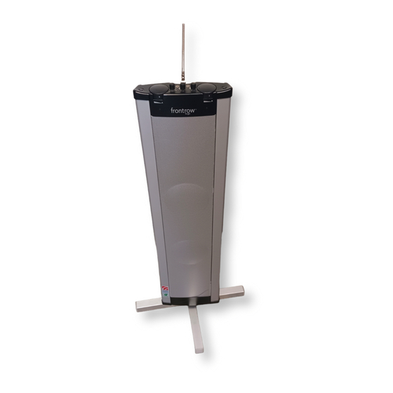
- Page 20 System Features: Receiver Channel A Channel Selector Channel B Channel Selector Antenna Channel A On/Off/Volume OptiVoice Selector Aux-In Jack (3.5mm Mono) Aux-In Volume Aux-Out Jack (3.5mm Mono) Aux-Out Volume 10. Channel B On/Off Volume 11. LED Indicators 12. Locator Hole...
-
Page 21: Chapter 4 System Features
System Features: Receiver (cont’d) 1. Speaker Battery Charge Indicator 2. Main Power On/Off Switch 3. Power Cord Jack 4. Locator Hole 5. Screw Hole... - Page 22 System Features: 925T front front back...
- Page 23 System Features: 925T (cont'd) 1. Belt clip 2. Battery compartment 3. Channel selector 4. Microphone input (2.5mm) 5. 3 position power switch 6. Power and low battery indicator light Mute...
- Page 24 System Features: 925H 1. LED indicator light 2. 3 position power switch 3. Channel selector 4. Battery compartment 5. Channel selector key (inside battery compartment) Mute...
- Page 25 System Features: 925C Front 1. Pocket 1 charging indicator 2. Pocket 1 full charge indicator 3. Pocket 2 charging indicator 4. Pocket 2 full charge indicator 5. DC power jack Back...
-
Page 26: Chapter 5 System Set-Up
System Setup: Receiver 1. Place speaker unit face down on a clean, flat surface 2. Open table stand arms 3. Place locator bolt of table stand into locator hole on the bottom of the speaker 4. Tighten fixing bolt to securely fix stand to unit 5. - Page 27 System Setup: Receiver (cont’d) 1. Attach antenna to top of speaker 2. Turn metal base of antenna clockwise until secured tightly (do not over-tighten)
- Page 28 System Setup: Receiver (cont’d) If using wall outlet: 1. Plug power cord into power jack 2. Plug power cord into wall socket 3. Turn speaker off...
- Page 29 System Setup: Receiver (cont’d) If using battery power: 1. Plug power cord into power jack 2. Plug power cord into wall socket 3. Turn speaker off Charge battery overnight before initial use. Red light =charging Green light = fully charged Green light = fully charged Green light Recharging time is approximately...
- Page 30 System Setup: 925t 1. Switch power off 2. Remove battery cover (push and slide off) 3. Insert two AA rechargeable NiMH batteries WARNING: Never recharge alkaline batteries! This will cause damage to the unit and will void the product warranty.
- Page 31 System Setup: 925H 1. Switch power off 2. Remove battery cover AA Rechargeable (turn counter-clockwise) NiMH batteries 3. Insert two AA rechargeable NiMH batteries WARNING: Never recharge alkaline batteries! This will cause damage to the unit and will void the product warranty.
- Page 32 System Setup: 925C 1. Plug power supply into power jack charger back on back of charger stand 2. Plug power supply into wall socket 3. Turn transmitters off and place into charger charger front charger front WARNING: Never recharge alkaline batteries! This will cause damage to the unit and will void the product...
- Page 33 System Setup: 925C (cont'd) 1. Charging: Red light = units are being charged Blinking red light = charging error. Improper batteries have been detected. Check your batteries and replace as required. Only NiMH AA batteries can be charged. Unit will not charge disposable Alkaline batteries or NiCad batteries.
-
Page 34: Chapter 6 Using Your System
Using Your System 925t 925H 1. Open battery compartment door and remove batteries 2. Remove channel adjustment key... - Page 35 Using Your System (cont’d) 1. Use a screwdriver to turn frequency selector to channel number that matches the channel on column speaker 2. If using both body-worn and hand-held transmitters set one transmitter channel to match Channel A on the speaker Channel A on the speaker Channel A column, and the other transmitter...
- Page 36 Using Your System (cont’d) 1. Plug microphone cord into mic jack on top of body-worn transmitter Mic cord...
- Page 37 Using Your System (cont’d) Put on microphone and adjust for proper distance from mouth. Maximum distance from mic to mouth is 6 in./15cm; 3 in./7.5cm is ideal.
- Page 38 Using Your System (cont’d) 1. Switch power on 2. Check indicator light: Continuous green = adequate power Continuous red = low battery Battery Life NiMH rechargeable AA = ~12 hours Alkaline disposable AA = ~15 hours...
- Page 39 Using Your System (cont’d) 1. Turn power on 2. Check indicator light: Continuous green = adequate power Continuous red = low battery Battery Life NiMH rechargeable AA = ~12 hours Alkaline disposable AA = ~15 hours...
- Page 40 Using Your System (cont’d) 1. Turn main power on 2. Turn channel on by turning Channel A and/or Channel B volume control knob(s) (remember that main power must also be on) 3. LED Indicators Green = on & receiving FM signal Red = on &...
- Page 41 Using Your System (cont’d) Follow steps 1 or 2 below to adjust FM volume setting to proper level. Two people are needed to set the volume level. It is difficult to hear your own voice and make adjustments to it. Note: The average volume setting is in the 3 position (see photo), but may change depending on room acoustics and noise level.
- Page 42 Using Your System (cont’d) OptiVoice Settings and Speech Intelligibility OptiVoice is a 3-position switch that automatically adjusts the sound quality of the primary speaker’s voice. It allows teachers to shape the sound of their voice medium position for moderate noise levels and helps to ensure maxium speech clar- ity in low, medium and high noise levels.
- Page 43 Using Your System (cont’d) 1. Set optiVoice switch according to room noise level. Medium position is the recommended setting for average noise levels. Low: Use in low-noise situations and for most natural voice reproduction. Medium: Best setting for average class- rooms where low-medium noise levels are present.
- Page 44 Using Your System (cont’d) 1. Using the appropriate adaptor cords, connect VCR, TV, CD, computer or other audio source to Aux-In port on top of speaker. 2. Use Aux-In Volume control to adjust volume NOTE: Aux-In can be used simultane- ously with both Channel A &...
- Page 45 Using Your System (cont’d) Aux out – connecting to computers or personal FM devices Use this to connect to a computer (to record audio for podcasting) or to a personal FM system (a device for the hearing impaired) 1. Connect cord to aux-out jack on the ToGo to the aux-in jack on the other device.
-
Page 46: Chapter 7 Speaker Placement & Mounting
Speaker Placement & Mounting Place speaker in a corner of the room fac- ing listeners. Mount speaker on wall using brackets or place speaker on a surface using a speaker stand. The bottom of the speaker should be about 3 ft./1m from the floor. (See setup tips on page 3). 3ft./1m... - Page 47 Speaker Placement & Mounting (cont’d) Without Mounting Template: 1. Measure 36" from the floor (maximum height) to the bottom of the lower bracket and mark mounting screw holes to be drilled. 2. Attach lower bracket to wall – If mounting to drywall, use 5 - #10 self-threaing 1.25" flathead phillips screws with drywall anchorsA 3. Place speaker on lower bracket and hold in place. Be sure the locator hole on the bottom of the speaker is securely mated with bolt in the lower bracket 4. Insert upper bracket into the locator hole on the top of the speaker and place against the wall. Do not depress the spring on the upper bracket. Mark the upper bracket holes, then carefully remove the speaker from the bottom bracket. Attach upper bracket to wall...
- Page 48 Speaker Placement & Mounting (cont’d) 5. Attach speaker to wall mount by inserting the upper bracket into the locator hole in the top of the speaker. Gently lift the speaker upwards and forward, mating the locator bolt on the lower wall mount bracket with the locator hole on the bottom of the speaker 6. Move swivel arm to align screw holes. Screw in fixing bolt through the swivel arm and into the screw hole in bottom of speaker. Tighten. To remove unit from wall mount, simply unscrew the fixing bolt and lift the speaker up and out. WARNING: To prevent injury, this apparatus must be securely attached to the wall using the wall brackets and mount- ing screws or with the floor stand supplied with the purchase of this system, both of which must be securely fastened by the fixing bolt.
-
Page 49: Chapter 8 Channel Mapping Tips
Channel Mapping Tips = s uggested placement of 925RS-216 speaker Channel A: 44 Channel A: 41 Channel A: 46 Channel A: 42 Channel B: 54 Channel B: 51 Channel B: 56 Channel B: 52 hallway Channel A: 48 Channel A: 45... - Page 50 Channel Mapping Tips (cont’d) Channel: 41 Channel: 42 Channel: 43 Channel: 44 Channel: 45 Channel: 46 Channel: 47 Channel: 48 Channel: 51 Channel: 52 Channel: 55 Channel: 54 Channel: 55 Channel: 56 Channel: 57 Channel: 58...
-
Page 51: Chapter 9 Troubleshooting
Troubleshooting no FM reception (Channel A, Channel speaker is receiving a signal but no B indicator does not have green light) sound is coming out • V erify the transmitter is turned on • V erify microphone is connected properly to transmitter and is working • V erify the frequency number on the correctly transmitter matches the frequency number on receiver feedback from speaker • Verify transmitter batteries are • T urn down the volume on the charged transmitter • V erify speaker antenna is connected • T urn down the volume on the speaker properly • M ake sure the person wearing the weak sound from speaker transmitter is not too close to the... - Page 52 • C heck to make sure metal objects are • I f using unplugged from wall outlet, not placed too close to transmitter or verify battery is installed. If installed, speaker (i.e. jewelry, metal shelves) verify it has been charged. If it does not charge, see below. red charge light is flashing when I • C onnect power supply to speaker and attempt to charge my transmitter charge for four hours. If speaker bat- • R eplace your batteries with a set of tery does not hold a charge, contact new NiMH cells. FrontRow Service department for...
-
Page 53: Chapter 10 Speaker Battery Replacement
Speaker Battery Replacement/Installation t/Installation 1. Turn off main switch and disconnect the power cord from the wall outlet and the rear base of the apparatus. 2. Remove 4 hex screws (3mm) on bottom and remove panel 3. Disconnect old battery and replace with new battery. -
Page 54: Chapter 11 System Specifications
System Specifications Channel # Channel A Channel # Channel B 41 ..216.025 MHz 51 ..216.525 MHz 42 ..216.075 MHz 52 ..216.575 MHz 43 . - Page 55 System Specifications (cont’d) two channel column speaker: 925RS-216 Carrier Frequency Range 216 - 217MHz Dimensions ( ) 29.5 x 7.2 x 3.4 in Modulation FM (F3E) 750 x 183 x 85 mm Output Power Maximum 36W RMS @ 4Ω x 2 Weight 12.5lbs. / 5.7 kg Power Requirements AC 110-200V Battery life 5 hours (rechargeable) ~50-60Hz, 1A max Recharging time 8 hours Battery 1 x NiMH rechargeable Frequency Response 100Hz – 9kHz (at rated output) Total Harmonic Distortion <1% (at rated output) @ 1kHz System signal-to-noise >70 dB (at rated output) ratio Inputs 1 x aux-in, 3.5 mm mono Output 1 x aux-out, 3.5 mm mono Controls Channel A/B on/off/volume Channel A/B channel selector aux-in volume, aux-out volume, OptiVoice...
- Page 56 System Specifications (cont’d) Body-worn Transmitter: 925T Handheld Mic Transmitter: 925H Carrier Frequency Range 216 - 217MHz Carrier Frequency Range 216 - 217MHz Modulation FM (F3E) Modulation FM (F3E) Operating Range >110ft./34m Operating Range >110ft. / 34m RF Output <15mW RF Output <15mW T otal Harmonic Distortion <0.5% Total Harmonic Distortion <0.5% Dynamic Range 100dB Dynamic Range 100dB Dimensions ( ) 2.5 x 3.5 x 1 in. Dimensions ( ) 2.1 x 9.3 in. 65 x 90 x 25 mm 54 x 237 mm Weight 1.8oz / 51g...
- Page 57 System Specifications (cont’d) Charging Stand: 925C Power Supply AC adaptor (DC 12V/ 0.5A) Indicator lights Power = red LED Charging = red LED Ready = green LED Charging Error = blinking red LED Dimensions ( ) 1.9 x 5.3 x 9 in 135 x 47 x 230 mm Weight 12.7oz / 360g...
-
Page 58: Chapter 12 Regulatory Information
Regulatory Transmitter any interference received, including interfer- This transmitter is authorized by rule under ence that may cause undesired operation. the Low Power Radio Service (47 C.F.R. Part IMPORTANT NOTE: To comply with FCC 95) and must not cause harmful interference RF exposure compliance requirements, only to TV reception or United States Navy SPASUR use supplied antenna that is sold with this installations. You do not need an FCC license transmitter. Use of any other antenna which to operate this transmitter. This transmitter has not been approved by the manufacturer may only be used to provide: auditory assis- will violate FCC rules and regulation and void tance to persons with disabilities, persons who the user’s authority to operate this device. require language translation, or persons in This device and its antenna(s) must not be educational settings; health care services to co-located or operating in conjunction with the ill; law enforcement tracking services under any other antenna or transmitter. agreement with a law enforcement agency; or automated maritime telecommunications system (AMTS) network control communica- tions. Two-way voice communications and all other types of uses not mentioned above are expressly prohibited. This device may not interfere with TV reception or federal government radar, and must accept... - Page 59 Regulatory (cont’d) receiver: part 15, subpart B cause harmful interference to radio communi- FrontRow To Go Receiver/Speaker 925RS cations. However, there is no guarantee that interference will not occur in a particular instal- lation. If this equipment does cause harmful Tested to comply with interference to radio or television reception, FCC Standards which can be determined by turning the equipment off and on, the user is encouraged to try to correct the interference by one or FOR HOME OR OFFICE USE more of the following measures: • Reorient or relocate the receiving antenna. This equipment has been tested and found • I ncrease the separation between the equip- to comply with the limits for a Class B digital ment and receiver. device, pursuant to Part 15 of the FCC Rules. • C onnect the equipment into an outlet on a These limits are designed to provide reason- circuit different from that to which the able protection against harmful interference receiver is connected. in a residential installation. This equipment • C onsult the dealer or an experienced radio/ generates, uses and can radiate radio fre- TV technician for help.
- Page 60 Regulatory (cont’d) FCC notes Part 95 The FrontRow To Go active learning sys- This transmitter is authorized by rule under tem is approved by the FCC (Federal the Low Power Radio Service (47 CFR Part Communications Commission). The use of 95) and must not cause harmful interfer- the system may be governed by specific FCC ence to TV reception or United States Navy rules and FCC licensing or notifications may SPASUR installations. You do not need be required. Consult your local FCC office an FCC license to operate this transmit- for detailed information. ter. This transmitter may only be used to provide auditory assistance to persons with Phonic Ear FM receivers and FM transmitters, disabilities, persons who require language when required, are approved by the Federal translation, or persons in educational set- Communications Commission (FCC) in the tings; health care services to the ill; law U.S. and Industry Canada. Other government enforcement tracking service under agree- approvals are available upon request. (Other ment with a law enforcement agency; or international regulations may also apply.) automated maritime telecommunication Any changes or modifications made to any system (AMTS) network control communica- government-approved element of this instru- tions. Two-way voice communications and ment, without the express approval of Phonic...
- Page 61 Regulatory (cont’d) This device may not cause interference with a TV receiver equipped with "rabbit-ear and must accept any interference received, antenna" and tuned to channel 13 should including interference that may cause unde- be conducted, at the perimeter of the users' sired operation.
- Page 62 Notes...
- Page 63 Notes...
- Page 64 u.s.a. 800.227.0735, then press 5 • canada 800.340.9894 • international +45 3917 7101 © 2010 Phonic Ear Inc. Phonic Ear and the names of Phonic Ear products are trademarks or registered trademarks of Phonic Ear Inc. in the U.S. and other countries. Product specifications and accessories subject to change without notice. 821-7404-105/Rev.
Need help?
Do you have a question about the 925RS and is the answer not in the manual?
Questions and answers