
Related Manuals for FrontRow To Go


Summary of Contents for FrontRow To Go
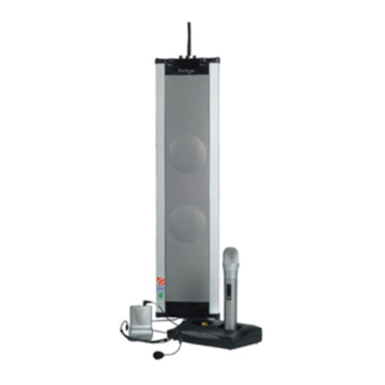
- Page 1 216MHz USER GUIDE 920SR speaker 921T body-worn transmitter 922T handheld transmitter 923C charging stand...
-
Page 2: Table Of Contents
....52-53 922T handheld transmitter features ..17 FrontRow To Go channel numbers and 923C charging stand features ..18 corresponding frequencies . -
Page 3: Introduction
You may have heard the term ‘sound field’ used to describe technology that improves classroom acoustics. Your FrontRow system fits under this category, but we call it an ‘active learning system’ because the benefits affect so much more than just sound. -
Page 4: Understanding Active Learning
understanding active learning and its benefits without active learning • distance • noise • echo with active learning • distance • noise • echo... -
Page 5: Setup Tips
IMPORTANT! Be sure you place your FrontRow To Go speaker and transmitter units on their charger overnight – for a minimum of 12 hours – before turning the power on and/or using them for the first time. Failing to do so can reduce battery capacity. - Page 6 3 feet/1 meter from the floor, or at level closest to the listener‘s ears. Fourth – Consider whether other FrontRow To Go, FrontRow Tempo, or other radio- based active learning systems are in use in the building, and set transmitter and receiver channels accordingly.
- Page 7 setup tips (cont’d) • Choose a table or surface top that is sturdy. Make sure the table or cabinet is structurally solid, sturdy and out of the way of foot traffic. • Properly mount and securely fasten the T-bar speaker stand onto the bottom of the speaker.
-
Page 8: Daily Operating Tips
daily operating tips In the morning – • Turn transmitter power ’on’ and put microphone on. • Turn speaker column power ’on’. The speaker should remain plugged into a wall power outlet during the day – with the power in the ‘on’ position. Turn power switch to the ‘off’... - Page 9 daily operating tips (cont’d) Battery care and maintenance tips – • The speaker battery will last approximately 2 years depending on usage. • When not in use, leave speaker plugged into wall outlet with power switch in ‘off ’ position. •...
-
Page 10: Daily Operating Tips
daily operating tips (cont’d) Do not coil the microphone – since it also acts as your antenna, coiling or wrapping the cord will affect its range and may also reduce its life. Speak at a normal level – the system is projecting your voice for you. -
Page 11: Parts And Accessories Included With System
parts and accessories included with system and/... - Page 12 column speaker receiver speaker table stand (920SR) (AT0823) body-worn transmitter wall mounting bracket (set of 2) (921T) (AT0820) and/or handheld transmitter elastic belt (922T) (AT0712) plug-in mic for body-worn transmitter AA rechargeable NiMH batteries (AT0655 shown) (AT0807) charging stand 11 channel changer screwdriver (923C) (330-3000-101) power supply, receiver...
-
Page 13: 920Sr Column Speaker Features
920SR column speaker features (top) - Page 14 power, low battery, and aux output level switch reception status indicator See page 42 for level setting chart for channel A antenna power switch and volume control for channel A wall mount hole reception status indicator for 10 extra antenna hole (not used) channel B 11 aux input jack (3.5mm, mono) power switch and volume...
- Page 15 920SR column speaker features (front and back)
- Page 16 13 speaker grille 19 power jack 14 two built-in speakers 20 channel selectors 15 internal rechargeable battery (non-user removable) 16 handle 17 main power on/off switch 18 power and charging indicator...
-
Page 17: Body-Worn Transmitter Features
921T body-worn transmitter features front back... - Page 18 921T body-worn transmitter features (cont’d) belt clip battery compartment volume control channel selector microphone input (2.5mm) 3 position power switch standby (mute) power and low battery indicator light...
-
Page 19: Handheld Transmitter Features
922T handheld microphone features LED indicator light 3 position power switch standby (mute) channel selector battery compartment channel selector key (inside battery compartment) -
Page 20: 923C Charging Stand Features
923C charging stand features front 1 power indicator 2 pocket 1 charging indicator 3 pocket 1 full charge indicator 4 pocket 2 charging indicator 5 pocket 2 full charge indicator back 6 power switch 7 DC power socket... -
Page 21: System Setup And Operation
system setup and operation attach antenna Attach antenna to top of speaker Turn metal base of antenna clock- wise until secured tightly (do not over-tighten) - Page 22 turn on main power if using wall outlet Plug power supply into power/charging socket Plug power supply into wall socket Turn speaker on if using already charged battery Turn speaker on NOTE: Light is not illuminated during normal battery operation NOTE: Battery operating time is 5-8 hours.
- Page 23 charge battery charge nightly after every use Plug power supply into power/charging socket Plug power supply into wall socket Recharging time is 8 hours if the battery is completely discharged and 4 to 7 hours if battery is only partially discharged. Red light = charging Flashing red/green (equal duration) = 80 -90% charged Long flash green, short flash red = fully charged...
- Page 24 insert batteries in body-worn transmitter Switch power off Remove battery cover (push and slide off) Insert two AA rechargeable NiMH batteries WARNING: Never recharge alkaline batteries! This will cause damage to the unit and will void the product warranty.
- Page 25 insert batteries in handheld microphone Switch power off AA Rechargeable Remove battery cover NiMH batteries (turn counter-clockwise) Insert two AA rechargeable NiMH batteries WARNING: Never recharge alkaline batteries! This will cause damage to the unit and will void the product warranty.
- Page 26 Plug power supply (AT0819) into wall socket Turn charger on charger front Turn transmitters off while charging When green charge ready indicator lights, the transmitter batteries are full charged and ready to go. (4 to 5 hours)
- Page 27 wait until green charge indicators light (4-5 hours) PWR: Red light = charger is turned on CHARGING: Amber light = units are being charged READY: Green light = units are fully charged ERROR: Blinking Amber light = charging error. Improper batteries have been detected.
- Page 28 921T number of either the 921T and/or the 922T transmitter(s). NOTE: Consider whether other FrontRow To Go, FrontRow Tempo, or other radio-based active learning systems are in use in the building, and set trans- mitter and receiver channels accordingly. Every transmitter in a building should be on its own channel.
- Page 29 activate receivers Channel A Turn receiver on by turning Channel B and/or volume control knob(s) to the right Check power indicator light (remember that main power must also be on – see Flash red once = adequate power Continuous red = low battery No light = battery does not have power and requires recharging or power supply is not connected properly...
- Page 30 setting FM volume Follow steps below to adjust volume setting to proper level. Two people are needed to set the volume level. It is difficult to hear your own voice and make adjustments to it. NOTE: The average volume setting is in the 11:00 position (see photo), but may change depending on room acoustics and noise level.
-
Page 31: 920Sr Speaker Placement And Mounting
920SR speaker placement and mounting speaker positioning Place speaker in a corner of the room facing listeners. Mount speaker on wall using brack- ets or place speaker on a surface using a speaker stand. The bottom of the speaker should be about 1 meter/3 feet from the floor. setup tips (See on page 3). - Page 32 channel mapping: placement diagram for multiple system installations (double channel - 8 rooms total) = suggested placement of 920SR speaker Channel A: 44 Channel A: 41 Channel A: 46 Channel A: 42 Channel B: 54 Channel B: 51 Channel B: 56 Channel B: 52 hallway Channel A: 48...
- Page 33 channel mapping: placement diagram for multiple system installations (single channel - 16 rooms total) Channel: 41 Channel: 44 Channel: 42 Channel: 43 Channel: 45 Channel: 46 Channel: 47 Channel: 48 Channel: 51 Channel: 52 Channel: 53 Channel: 54 Channel: 55 Channel: 56 Channel: 57 Channel: 58...
- Page 34 wall mounting (option 1) Attach brackets to wall AT0820 Screw mounting brackets to top and bottom of speaker...
- Page 35 mounting on floor stand (option 2) Screw speaker stand into hole on bottom of speaker. • Turn clockwise to tighten • Turn counter-clockwise to loosen AT0823 AT0824 floor stand is also available...
- Page 36 seal wall mounting hole if using table stand Place plastic plug into mounting bracket hole on top of speaker to keep out dust...
-
Page 37: Operation
921T body-worn transmitter operation plug microphone in Plug microphone cord into Boom mic cord jack on top of body-worn transmitter... - Page 38 put on microphone and adjust for proper distance from mouth Maximum distance from mic to mouth is 6 in/(15cm); 3 in/(7.5cm) is ideal. optional optimum AT0814 earhook mic AT0655 boom mic (two wearing options) #### performance: #### performance: 15cm/ 7.5cm/3in 6in max.
-
Page 39: Battery Life
turn power on Switch power on Check indicator light: Continuous green = adequate power Continuous red = low battery battery life NiMH rechargeable AA = 12 hours (approx.) Alkaline disposable AA = 15 hours (approx.) WARNING: Never recharge alkaline batteries! This will cause damage to the unit and will void the product warranty. - Page 40 adjust transmitter(s) frequency Use a screwdriver to turn frequency selector to channel number that match- es the channel set on column speaker If using both body-worn and hand- held transmitters set one transmitter Channel A channel to match a 921T the speaker column, and the other transmitter channel to match Channel B...
- Page 41 adjust body-worn transmitter volume Increase transmitter volume for greater mic sensitivity and sound clarity Reduce transmitter volume if feed- back occurs...
- Page 42 activate standby/mute mode standby Activate mode to eliminate white noise when not speaking MUTE: Standby mode can also be used as a microphone/transmitter mute switch. The mute feature allows teachers to have a private conversation without needing to turn the transmitter...
-
Page 43: Operation
922T handheld transmitter operation turn power on Turn power on by pushing power switch up... - Page 44 check indicator light Check indicator light: Continuous green = adequate power Continuous red = low battery battery life NiMH rechargeable AA = 12 hours (approx.) Alkaline disposable AA = 15 hours (approx.) WARNING: Never recharge alkaline batteries! This will cause damage to the unit and will void the product warranty.
- Page 45 remove channel adjustment key Open battery compartment door and remove batteries Remove channel adjustment key...
- Page 46 adjust transmitter channel to match receiver channel Using adjustment key, turn channel frequency selector to channel number that matches the channel set on column speaker NOTE: Never operate two transmitters on the same channel or interference will result. To use two transmitters, set the first to match receiver Channel A and the second...
-
Page 47: Standby Mode
standby mode Activate standby mode to mute voice and eliminate white noise when not speaking... - Page 48 #### compatible performance accessory transmitter comments (no adaptor rating needed cord required) 921T #### none FrontRow To Go 922T #### none FrontRow To Go 330T #### none FrontRow Tempo 300TS-216 none best when used with AT0655 boom mic Sprite Lexis transmitter...
-
Page 49: Tv, Cd, Vcr, Etc
aux in – connecting to TV, CD, VCR, etc. connecting speaker to TV, CD, VCR, etc. Using either the AT0532-05 or 300-6332-107 adaptor cords, connect VCR, TV, CD, computer AUX IN or other audio source to port on top of speaker AUX IN VOLUME control to adjust volume... -
Page 50: Aux Out - Connecting To Personal Devices
aux out – connecting to personal FM devices connecting to S or other transmitter OLARIS ISTENER PRITE (for rebroadcast of audio to students with hearing impairment) Connect AT0532-05(ft) cord to input jack of either S OLARIS , or other trans- ISTENER PRITE mitter. - Page 51 aux out transmitter compatibility chart and level setting guide NOTE: Common transmitters and recommended level settings are shown below. Because the level setting is universal, other transmitters not listed below may be used as well – simply set the level to the position at which the receiver wearer hears a strong distortion-free signal. product name/part aux in jack size aux out level setting...
-
Page 52: Additional System Accessories
additional system accessories microphone options AT0816 AT0291-L AT0655 AT0814 FM collar microphone earhook microphone directional microphone behind-the-neck with mute switch with lavalier cord boom microphone receiver accessories AT0820 AT0823 AT0824 AT0822 AT0801 wall mounting bracket speaker floor stand speaker table stand carrying bag aux-box (allows up (set of 2) - Page 53 additional system accessories (cont’d) transmitter accessories AT0532-15 AT0529A 310-2544-1341 AT0807 auxiliary input/ transmitter antenna aux-out adaptor plug AA rechargeable output cable (3.5mm– 2.5mm) NiMH batteries (3.5mm–dual RCA) (15ft/4.6m)
-
Page 54: Troubleshooting
troubleshooting no FM reception (Channel A, Channel speaker is receiving a signal but no B indicator does not have green light) sound is coming out • Verify the transmitter is turned on • Verify microphone is connected properly to transmitter and is working correctly •... -
Page 55: Troubleshooting
troubleshooting (cont’d) speaker does not turn on (power speaker is picking up FM interference indicator does not flash red) or hum • Verify main power switch on the bottom of • Check to make sure no other wireless sys- the unit is turned on tems are operating on similar frequencies •... -
Page 56: Frontrow To Go Channel Numbers And Corresponding Frequencies
FrontRow To Go channel numbers and corresponding frequencies Channel # Channel A Channel # Channel B 41 ... 216.025 MHz 51 ..216.525MHz 42 . -
Page 57: Product Specifications
product specifications two channel column speaker: 920SR carrier frequency range/ dimensions ( 216.025 –216.875MHz 100 x 660 x 145 mm/ 3.9 x 26 x 5.7 in frequencies 16 total weight 5kg/11lbs modulation FM (F3E) recharging time 8 hours for initial charging output power maximum 36W @ 4! x 2 4 –... - Page 58 product specifications (cont’d) body-worn transmitter: 921T carrier frequency range/ battery 216.025 –216.875MHz NiMH rechargeable (1600mA); alkaline disposable (2AA) frequencies 16 total battery life NiMH rechargeable: 12 hours (approx.) modulation FM (F3E) alkaline disposable: 15 hours (approx.) total harmonic distortion <1.5% frequency response 50Hz to 12KHz recharging time...
- Page 59 product specifications (cont’d) handheld mic transmitter: 922T charging stand: 923C power supply carrier frequency range/ AC adaptor (DC 12V/ 0.5A) 216.025 –216.875MHz frequencies 16 total (see chart below) indicator lights LED green = battery ready LED orange = recharging dynamic microphone LED red = power on antenna built-in...
-
Page 60: Regulatory Approvals And Clearances
regulatory approvals and clearances transmitter IMPORTANT NOTE: To comply with FCC RF This transmitter is authorized by rule under the Low exposure compliance requirements, only use sup- Power Radio Service (47 C.F.R. Part 95) and must plied antenna that is sold with this transmitter. not cause harmful interference to TV reception or Use of any other antenna which has not been United States Navy SPASUR installations. - Page 61 (cont’d) receiver: part 15, subpart B radio communications. However, there is no guar- FrontRow To Go Receiver/Speaker 920SR antee that interference will not occur in a particu- lar installation. If this equipment does cause harmful interference to radio or television recep-...
- Page 62 (cont’d) FCC notes Part 95 The FrontRow To Go active learning system is This transmitter is authorized by rule under the approved by the FCC (Federal Communications Low Power Radio Service (47 CFR Part 95) and Commission).
-
Page 63: Regulatory Approvals And Clearances
regulatory approvals and clearances (cont’d) This device may not cause interference and must If TV channel 13 is used in the area, the installer accept any interference received, including inter- shall reduce or adjust the RF radiated power so ference that may cause undesired operation. that near-by TV channel 13 receivers do not receive radio interference from the system These devices may not interfere with TV recep-... - Page 64 is a division of RONT u.s.a. 800.227.0735, then press 5 • canada 800.263.8700 • international +45 3917 7101 © 2005 Phonic Ear Inc. Phonic Ear and the names of Phonic Ear products are trademarks or registered trademarks of Phonic Ear Inc. in the U.S. and other countries.
Need help?
Do you have a question about the To Go and is the answer not in the manual?
Questions and answers