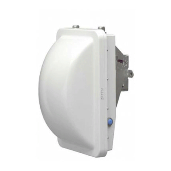
Ruckus Wireless ZoneFlex 7731 User Manual
802.11n point to point wireless bridge
Hide thumbs
Also See for ZoneFlex 7731:
- User manual (110 pages) ,
- Getting started manual (56 pages) ,
- Installation manual (64 pages)

Related Manuals for Ruckus Wireless ZoneFlex 7731


Summary of Contents for Ruckus Wireless ZoneFlex 7731
-
Page 1: User Guide
Ruckus Wireless ® ZoneFlex 7731 802.11n ® Point to Point Wireless Bridge User Guide Part Number 800-70250-001 (Rev B) Published December 2009 www.ruckuswireless.com... -
Page 3: Table Of Contents
Contents About This Guide Document Conventions ..........i Related Documentation . - Page 4 3 Navigating the Web Interface Logging Into the ZoneFlex Web Interface........57 Navigating the Web Interface.
-
Page 5: About This Guide
About This Guide About This Guide This guide describes how to install, configure, and manage the Ruckus Wireless® ZoneFlex® 7731 802.11n Point to Point Wireless Bridge. This guide is written for those responsible for installing and managing network equipment. Consequently, it assumes that the reader has basic working knowledge of local area networking, wireless networking, and wireless devices. -
Page 6: Related Documentation
When contacting us, please include the following information: Document title ■ Document part number (on the cover page) ■ Page number (if appropriate) ■ For example: Ruckus Wireless ZoneFlex 7731 802.11n Point to Point Wireless Bridge User Guide ■ Part number: 800-70250-001 ■ Page 88 ■... -
Page 7: Introducing The Zoneflex Wireless Bridge
Ruckus Wireless sales representative. Package Contents The standard ZoneFlex 7731 Wireless Bridge package contains two ZoneFlex 7731 units and two sets of accessories (one for each unit). A single unit package contains one ZoneFlex 7731 unit and one set of accessories. Refer to... - Page 8 Unpacking the ZoneFlex Wireless Bridge Table 1. Package contents Single Unit Two Units • One ZoneFlex 7731 Point to Point • Two ZoneFlex 7731 Point to Point Wireless Bridge Wireless Bridge units, pre-provisioned as a “Root Bridge” and a “Non-Root •...
- Page 9 Introducing the ZoneFlex Wireless Bridge Unpacking the ZoneFlex Wireless Bridge Mounting Kit Contents Each mounting kit contains: Dynamic bracket ■ Static bracket ■ Steel clamps (2 pieces) ■ Machine screws (8 pieces) ■ Hex bolts (4 pieces) ■ Split lock washers (4 pieces) ■...
- Page 10 Introducing the ZoneFlex Wireless Bridge Unpacking the ZoneFlex Wireless Bridge Bottom Cover and Accessories Each bottom cover accessory bag contains: Bottom cover of the Wireless Bridge ■ DC terminal block ■ 20mm x 30mm sealing strips (2 pieces) ■ Sealing plug ■...
-
Page 11: Getting To Know The Hardware Features
Introducing the ZoneFlex Wireless Bridge Getting to Know the Hardware Features Getting to Know the Hardware Features Figure 3 Figure 5 identify the Wireless Bridge features that are relevant to the installation and mounting instructions that this guide provides. Before you begin the installation process, Ruckus Wireless recommends that you become familiar with these features. - Page 12 Introducing the ZoneFlex Wireless Bridge Getting to Know the Hardware Features Table 2. LEDs and bottom panel connectors Label Description LEDs “LED Colors and What They Mean” below for more information. RJ45 LAN port that supports Power over Ethernet (PoE) and 10/ 100/1000 Mbps network connections Reset Using a pointed object (for example, a pen), press this...
- Page 13 Introducing the ZoneFlex Wireless Bridge Getting to Know the Hardware Features LED Colors and What They Mean The ZoneFlex 7731 Wireless Bridge includes 6 dual color LEDs. The LEDs function in two modes, normal operation mode and aiming mode. Figure 4.
- Page 14 Press and hold the blue Aiming button for four (4) seconds to initiate aiming between the root and non-root bridge. Resetting the ZoneFlex 7731 to its factory defaults will result in loss of all CAUTION: configuration settings, including the pre-provisioning (pairing of the root and non-root bridge) settings that were enabled prior to shipping.
- Page 15 Getting to Know the Hardware Features External Antenna Connectors The ZoneFlex 7731 Wireless Bridge includes one purpose designed internal directional antenna. If you want to extend the range of your wireless network, you can connect an external high gain 5GHz antenna to the two standard N-type external antenna connectors on the top panel of the Wireless Bridge.
- Page 16 Introducing the ZoneFlex Wireless Bridge Getting to Know the Hardware Features...
-
Page 17: Installing The Wireless Bridge
The ZoneFlex 7731 units are shipped in pre-configured pairs so that you do not need to manually configure the units prior to installation. Simply install the root bridge at the edge of your core network, install the non-root bridge at the edge of the network you want to bridge, aim the pair, and you’re done. -
Page 18: Determine The Optimal Mounting Location And Orientation
Installing the Wireless Bridge Before You Begin 10mm ratchet wrench ■ 3mm Phillips screwdriver (if you will be using DC power) ■ Electric drill with 8mm drill bit (if mounting on a flat surface) ■ NOTE: At the beginning of each procedure, this guide lists the specific tools, accessories, and equipment that you will need to complete the procedure. -
Page 19: Become Familiar With The Installation Components
Before You Begin Become Familiar with the Installation Components The ZoneFlex 7731 Wireless Bridge is designed for installation in an outdoor environ- ment, such as an exterior wall, or the roof overhang of a building, or a streetlight pole. Refer to Figure 7 for the components involved in a typical installation. -
Page 20: Decide How You Will Supply Power To The Wireless Bridge
Installing the Wireless Bridge Pre-Installation Configuration Be sure that grounding is available and that it meets local and national CAUTION: electrical codes. For additional lightning protection, use lightning rods and lightning arrestors. WARNING: The Ruckus Wireless PoE injector (if supplied with your Wireless Bridge) is for indoor use only. -
Page 21: What You Will Need
To customize any of these settings before deploying the bridge pair, you will need to connect an administrative computer directly to each ZoneFlex 7731 using the unit’s default IP address, and provide power using either DC power or Power over Ethernet before you can access the unit’s Web interface. -
Page 22: Access The Web Interface
5. Connect the power jack to the DC 48V IN connector on the PoE injector, and then plug the power adapter into a power source. 6. Check the power LED on the ZoneFlex 7731 to ensure power is being supplied to the bridge. - Page 23 Installing the Wireless Bridge Pre-Installation Configuration Figure 8. Connect the Ethernet cables and power adapter to the PoE injector To Admin To Bridge Computer To AC Power Source You have completed connecting the Wireless Bridge to a PoE power source. Use DC Power To use DC to power the Wireless Bridge, you need to connect a DC cable (not supplied with the Wireless Bridge) to the DC terminal block.
- Page 24 Installing the Wireless Bridge Pre-Installation Configuration 5. Connect the DC terminal block to the 12V DC port on the Wireless Bridge. Figure 10. Connect the DC terminal block to the 12V DC port 6. Connect the DC cable to a DC power source (for example, a battery). You have completed connecting the Wireless Bridge to a DC power source.
- Page 25 Installing the Wireless Bridge Pre-Installation Configuration NOTE: Make sure that you configure the Local Area Connection properties, not the Wireless Network Connection properties. 3. When the Local Area Connection Properties dialog box appears, select Internet Protocol (TCP/IP) from the scrolling list, and then click Properties. The Internet Protocol (TCP/IP) Properties dialog box appears.
- Page 26 Step 3: Connect the Wireless Bridge to the Admin Computer If you have not already done so, connect the admin computer to the ZoneFlex 7731 using an Ethernet cable, or two Ethernet cables and a PoE injector if you are using Power over Ethernet (see “Connect the Ethernet cables and power adapter to the...
- Page 27 Installing the Wireless Bridge Pre-Installation Configuration Figure 13. Ruckus ZoneFlex 7731 Wireless Bridge Status :: Wireless page 8. Continue to “Step 5: Change the Country Code”. Step 5: Change the Country Code Change the Country Code setting to your location and reboot the bridge for updates to take effect.
- Page 28 Installing the Wireless Bridge Pre-Installation Configuration Figure 14. Country code warning message 3. Click OK to continue. 4. Click Update Settings to confirm changes. 5. A message indicating that your parameters were saved and a reboot is required appears. Figure 15. Your parameters were saved;...
- Page 29 Installing the Wireless Bridge Pre-Installation Configuration Figure 16. Reboot the wireless bridge to apply country code change 7. When the reboot is completed, log in again to continue making configuration changes. Do not change the Channel setting until after the Country Code has been CAUTION: set for both units.
- Page 30 Pre-Installation Configuration Change the IP Address By default, the Ruckus Wireless ZoneFlex 7731 Wireless Bridge units come with DHCP enabled and will automatically acquire an IP address from a DHCP server if one is discovered on the network. If no DHCP server is found, the Root bridge and Non-Root bridge have pre-configured IP addresses assigned to prevent conflict.
- Page 31 Installing the Wireless Bridge Pre-Installation Configuration NOTE: This process may take several minutes. Do not unplug the ZoneFlex 7731 while it is updating its IP address. Change Device Name, Location, User Name and Password In addition to the IP address, you can also change the device name, location, login name and password on this page.
- Page 32 Installing the Wireless Bridge Pre-Installation Configuration Figure 19. Enable Management VLAN Click Enabled next to Management VLAN (default: Disabled) and enter the VLAN ID in the field below. Click Update Settings to confirm changes. Change SSID and Encryption Method NOTE: If these changes are made after the units are mounted, make the changes to the remote unit, whether it be Root or Non-Root, first to avoid loss of connection.
- Page 33 Administration > Management. By default, the network management method is set to Auto, meaning that the ZoneFlex 7731 will be managed by FlexMaster server if available, and by SNMP if no FlexMaster server is found on the network.
- Page 34 Installing the Wireless Bridge Pre-Installation Configuration If you want to manage the Wireless Bridge using SNMP even when a FlexMaster server is available, select SNMP only under “TR069/SNMP Management Choice,” then enter the Read-Only/Read-Write Community information, along with the SNMP Trap server IP address in the appropriate spaces.
- Page 35 Installing the Wireless Bridge Pre-Installation Configuration Step 7: Change Non-Root Bridge Configuration Settings Repeat steps 1-6 for the Non-Root bridge for any changes you made to the Root bridge settings. If you did not make any changes, you only need to repeat step 1 to provide power and Ethernet to the non-root bridge, then proceed to Step 8: Test the Link Between the...
- Page 36 Figure Figure 25. SpeedFlex Results page You have finished accessing and testing the link between the ZoneFlex 7731 Wireless Bridge pair. Step 9: Disconnect the Wireless Bridge from the Administrative Computer 1.
-
Page 37: Provisioning And Associating The Wireless Bridge Pair (Optional)
7731 units as the Root bridge and the other as the Non-Root bridge. NOTE: The ZoneFlex 7731 Wireless Bridge units are shipped already paired so auto provisioning will not be needed in the field unless it becomes necessary to restore factory default settings. -
Page 38: Manual Provisioning Using The Web Interface
“Step 5: Change the Country Code” page 2-21. Manual Provisioning Using the Web Interface The ZoneFlex 7731 Wireless Bridge units can also be manually provisioned using the Web interface. The procedure for Web based provisioning is as follows: 1. Log in to the Web interface of the unit that you will designate as the Root bridge. - Page 39 Installing the Wireless Bridge Provisioning and Associating the Wireless Bridge Pair (Optional) Figure 26. Manual Provisioning Wizard 3. Select Root Bridge and click Next to continue. 4. Adjust settings on the WLAN configuration page if necessary, and click Next to continue.
-
Page 40: Associating
Installing the Wireless Bridge Provisioning and Associating the Wireless Bridge Pair (Optional) Figure 28. Reboot after completing the Provisioning Wizard 7. Click Reboot to confirm changes and reboot the bridge. 8. Repeat steps 2-7 for the Non-Root bridge, selecting Non-Root Bridge on Step 3, and making sure you enter the same values on the WLAN Configuration page as those of the Root bridge. - Page 41 Installing the Wireless Bridge Provisioning and Associating the Wireless Bridge Pair (Optional) Figure 29. No association established The units will automatically associate with one another after about 1 to 2 minutes. Once the association is complete, the page will refresh and the Connected Device information will be displayed, as shown: Figure 30.
-
Page 42: Deploying The Wireless Bridge
Installing the Wireless Bridge Deploying the Wireless Bridge Deploying the Wireless Bridge In this step, you will connect the Wireless Bridge to the network from its mounting location. Step 1: Complete the Power Connections The Wireless Bridge supports both PoE and DC power and it can be connected to both power sources at the same time. - Page 43 Installing the Wireless Bridge Deploying the Wireless Bridge Figure 31. Connect the Ethernet cables and power adapter to the PoE injector To Outdoor Bridge To Network To AC Power Source 7. Take out one of the 20mm x 30mm sealing strips from the accessories bag. 8.
- Page 44 Installing the Wireless Bridge Deploying the Wireless Bridge Figure 33. Install the white P-clip clamp P-clip cable clamp Sealing strip You have completed setting up the PoE power connection. Use DC Power To use DC to power the Wireless Bridge, you need to connect a DC cable (not supplied with the Wireless Bridge) to the DC terminal block.
- Page 45 Installing the Wireless Bridge Deploying the Wireless Bridge Figure 34. Connect the ground wire to the V- terminal and the +12V DC wire to the V+ terminal 12V DC Wire to V+ Terminal Ground Wire to V- Terminal 4. Using a 3mm Phillips screw, tighten the wiring terminal screws. Screw torque value must be 20.5 mN-m ±...
- Page 46 Installing the Wireless Bridge Deploying the Wireless Bridge WARNING: Do not apply power to the Wireless Bridge at this point. You should connect the Wireless Bridge to a power source only after you finish connecting all other components in “Step 3: Connect the Wireless Bridge to the Network” page Figure 36.
- Page 47 PoE and DC power. Figure 38. Typical installation components using both PoE and DC power sources DC power source DC cable ZoneFlex 7731 Outdoor Wireless Bridge 18 AWG min green-and-yellow 18 AWG min...
-
Page 48: Attaching The Mounting Brackets
Installing the Wireless Bridge Deploying the Wireless Bridge WARNING: Do not apply power to the Wireless Bridge until you finish connecting all other components. 1. Take the root bridge to its mounting location. 2. Verify that the Cat5e FTP cable (outdoor-rated) from the Wireless Bridge is long enough to reach the PoE injector that is installed indoors. - Page 49 Installing the Wireless Bridge Deploying the Wireless Bridge Step 1: Attach the Static Bracket to the Mounting Surface The procedure for attaching the bracket to the mounting surface depends on whether you are mounting the Wireless Bridge to a flat surface or a pole. Attaching the Bracket to a Flat Surface ■...
- Page 50 Installing the Wireless Bridge Deploying the Wireless Bridge 6. Place a metal cone on each wall anchor, and then place a flat washer on top of the metal cone. Figure 40. Insert a wall anchor into each hole that you drilled, and then place a metal cone and a flat washer on top...
- Page 51 Installing the Wireless Bridge Deploying the Wireless Bridge 7. Align the two screw holes on the bracket with the wall anchors that you inserted earlier. Figure 41. Align the screw holes on the bracket with the wall anchors 8. Use two hex nuts to attach the bracket to the mounting surface. Figure 42.
- Page 52 Installing the Wireless Bridge Deploying the Wireless Bridge 10. Continue to “Step 2: Attach the Dynamic Bracket to the Wireless Bridge”. Attaching the Bracket to a Pole The Wireless Bridge can be mounted vertically on a 30mm to 60mm (1.18 in. to 2.36 in.) pole.
- Page 53 Installing the Wireless Bridge Deploying the Wireless Bridge 2. Use the clamps to attach the bracket to the pole. Figure 44. Use the clamps to attach the bracket to the pole 3. Using a 10mm flathead screwdriver, tighten the clamp locks to secure the bracket to the pole.
- Page 54 Installing the Wireless Bridge Deploying the Wireless Bridge Step 2: Attach the Dynamic Bracket to the Wireless Bridge 1. Place the dynamic bracket onto the flat side of the Wireless Bridge so that the four screw holes on the bracket align with the four screw holes on the Wireless Bridge.
-
Page 55: Mounting The Wireless Bridge
Installing the Wireless Bridge Mounting the Wireless Bridge 3. Using a 6mm Phillips screwdriver, tighten the four machine screws to fasten the bracket to the Wireless Bridge. Screw torque value must be 0.4 N-m ± 0.1 N-m. Figure 47. Fasten bracket to the Wireless Bridge 4. - Page 56 Installing the Wireless Bridge Mounting the Wireless Bridge • (For mounting on a vertical pole) The side of the Wireless Bridge with the antenna connectors is at the top, especially if you are planning to install external antennas. Figure 48. Joining the two brackets in a vertical pole installation 2.
- Page 57 Installing the Wireless Bridge Mounting the Wireless Bridge NOTE: Make sure the screw-washer assembly is in correct order. The split-lock washer should be in the middle and the flat washer should touch the bracket. 4. Repeat Step 3 for the lower mounting hole on the other side. 5.
-
Page 58: Mounting And Connecting The External Antenna (Optional)
Installing the Wireless Bridge Mounting the Wireless Bridge Mounting and Connecting the External Antenna (Optional) If you want to extend the range of your wireless bridge connection, you can connect an external patch antenna to the standard N-type female connectors on the Wireless Bridge. -
Page 59: Aiming The Bridge Pair
• If the unit is in Aiming mode but there is no association between the two bridge units, all LEDs will cycle yellow until the two ZoneFlex 7731 units have associ- ated. 2. Adjust the azimuth and elevation of the first unit to maximize the Aiming LED indicators. -
Page 60: Verifying The Connection
ZoneFlex 7731 to your desired orientation. NOTE: The cable end of the ZoneFlex 7731 should always be pointing down. 5. Once the ZoneFlex 7731 is in the proper orientation, tighten the thumb screws flush to the bracket. 6. Using a 10mm ratchet wrench, tighten the two hex bolts to fix the unit's orientation. -
Page 61: Viewing Connected Device Information
Installing the Wireless Bridge Verifying the Connection Figure 52. Viewing connected device from the Web interface Viewing Connected Device Information The Connected Device information box displays the following information: Table 7. Connected Device information box Item Description IP Address This is the IP address of the connected device. MAC Address This is the MAC address of the connected device. - Page 62 Verifying the Connection 4. Click Start to begin testing 5. Once the test is completed, the following result page is displayed. Figure 53. SpeedFlex Performance Test succeeded You have completed installation and aiming of the ZoneFlex 7731 Wireless Bridge pair.
-
Page 63: Navigating The Web Interface
Navigating the Web Interface In This Chapter Logging Into the ZoneFlex Web Interface ........57 Navigating the Web Interface . -
Page 64: Navigating The Web Interface
Table 8 lists the Web interface features that are identified in Figure Figure 54. ZoneFlex 7731 Wireless Bridge Web interface elements Logout Button Auto-Update Button Help Button Menu Workspace Table 8. - Page 65 Navigating the Web Interface Navigating the Web Interface Table 8. ZoneFlex 7731 Wireless Bridge Web interface elements Element Description Help Button Click this button to open a help window with information related specifically to the options currently displayed in the workspace.
- Page 66 Navigating the Web Interface Navigating the Web Interface...
-
Page 67: Configuring The Wireless Bridge
Configuring the Wireless Bridge In This Chapter Configuring Wireless System Settings ......... 61 Wireless Link Configuration Settings. - Page 68 Configuring the Wireless Bridge Configuring Wireless System Settings Figure 55. The Wireless Configuration page Table 9. Wireless configuration options Setting Description Channel This option lets you select the channel used by the network. You can choose SmartSelect, or choose one of a specific number of channels.
- Page 69 RTS/CTS threshold settings. For more information, see “Setting Threshold Options” page Encryption Method By default, both of the ZoneFlex 7731 units are shipped with WPA2 encryption enabled. For more information, see either “Using WEP” page 72 “Using WPA”...
-
Page 70: Advanced Wireless Settings
Configuring the Wireless Bridge Configuring Wireless System Settings Selecting the incorrect country or region may result in violation of appli- CAUTION: cable laws. If you purchased the bridge in the United States, you do not need to manually set the country code. Ruckus Wireless APs that are sold in the US are preconfigured with the correct country code and this setting cannot be changed. - Page 71 Configuring the Wireless Bridge Configuring Wireless System Settings Table 10. Advanced Wireless Configuration Options Option Description Transmit Power The default setting is Full. Select the level of transmit power from the drop-down menu. This option sets the maximum transmit power level relative to the predefined power (this value differs according to the current country code).
- Page 72 Configuring the Wireless Bridge Configuring Wireless System Settings Setting Threshold Options The following options allow you to fine-tune the “Protection Mode” behavior, set previously on the Configuration :: Wireless :: Advanced page. After activating a Protection Mode, you can customize the threshold settings to determine which protection mode settings are put into effect and when.
-
Page 73: Configuring Bridge Settings
Configuring the Wireless Bridge Configuring Wireless System Settings Figure 57. Threshold settings Configuring Bridge Settings This section describes how to view and configure physical, network and management settings specific to this bridge unit. Topics discussed include: Setting device name and location ■... - Page 74 3. Entering GPS coordinates enables you to quickly identify the unit using Flex- Master’s map feature. See your FlexMaster User Guide for more information. Enabling the Internal Heater The ZoneFlex 7731 Wireless Bridge includes an optional internal heater to provide extended operating temperature in outdoor environments with temperatures ranging °...
-
Page 75: Obtaining And Assigning An Ip Address
Configuring the Wireless Bridge Configuring Wireless System Settings Changing the Username and Password The default username (super) and password (sp-admin) should be changed after installation to prevent unauthorized access. To change the login information, 1. Go to Configuration > Bridge. 2. - Page 76 Configuring the Wireless Bridge Configuring Wireless System Settings Figure 59. Changing IP address settings To change the method of acquiring an IP address: 1. Go to Configuration > Bridge. 2. Verify that Connection Type is set to Static IP. 3. When the Static IP options appear, you can make changes to the following settings: •...
-
Page 77: Configuring Wireless Security
Figure 60. Renew/Release DHCP Configuring Wireless Security By default, the ZoneFlex 7731 Wireless Bridge uses WPA2 (WiFi Protected Access) as its encryption and authorization method. WPA2 provides enhanced security compared to the older WEP (Wired Equivalent Privacy) and WPA methods. - Page 78 Configuring the Wireless Bridge Configuring Wireless System Settings Using WEP To use WEP as the WLAN encryption method 1. Go to Configuration > Wireless. The Configuration :: Wireless page appears. 2. Click the Encryption Method menu, and then click WEP. An additional set of WEP- specific encryption options appear on this page.
- Page 79 Configuring the Wireless Bridge Configuring Wireless System Settings Table 12. WEP settings Key Entry Method • Hexadecimal: The encryption key only accepts hexadecimal characters (0-9, A-F). • ASCII Text: The encryption key accepts ASCII characters. Passphrase This assists in automatic key generation. Enter some text and click the Generate button.
- Page 80 Configuring the Wireless Bridge Configuring Wireless System Settings Figure 62. WPA settings 3. Review the encryption settings listed in Table 13 and make changes as preferred. Table 13. WPA settings Encryption Setting Description WPA Version Options are WPA, WPA2 or WPA Auto. •...
- Page 81 Configuring the Wireless Bridge Configuring Wireless System Settings 4. Click Update Settings to save and apply the changes. A confirmation message appears at the top of the page.
- Page 82 Configuring the Wireless Bridge Configuring Wireless System Settings...
-
Page 83: Managing The Wireless Bridge
Managing the Wireless Bridge In This Chapter Managing Firmware Upgrades ..........77 Changing the Administrative Login Settings . -
Page 84: Upgrading Manually Via The Web
Managing the Wireless Bridge Managing Firmware Upgrades Figure 63. The Maintenance :: Upgrade page Upgrading Manually via the Web 1. In the Upgrade Method options, click Web. 2. Click the Web Options URL field, and then type the URL of the download Web site. - Page 85 Managing the Wireless Bridge Managing Firmware Upgrades Figure 64. Firmware upgrade in progress 5. After the upgrade is completed, the bridge will reboot automatically. The “Reboot in Progress” page will be shown. Do not disconnect power from the bridge during reboot.
-
Page 86: Upgrading Manually Via Ftp Or Tftp
Managing the Wireless Bridge Managing Firmware Upgrades Figure 66. Viewing the current firmware version Upgrading Manually via FTP or TFTP 1. In the Upgrade Method options, click FTP or TFTP. 2. Click the Firmware Server field, and then type the URL or IP address of the server. Do not change any of the Image Control File, Username, or Password CAUTION: entries. -
Page 87: Scheduling Automatic Upgrades
Managing the Wireless Bridge Managing Firmware Upgrades Scheduling Automatic Upgrades The automatic upgrade feature lets you set the bridge to periodically query the Ruckus Wireless firmware server to check for new firmware versions, upgrade when a new version is found, and reboot the system at a specific time of day most likely to avoid causing network interruptions. -
Page 88: Scanning For Interference
Managing the Wireless Bridge Scanning for Interference Scanning for Interference The ZoneFlex 7731 includes a Site Survey tool that allows you to scan for other wireless networks nearby which may impact bridge to bridge performance. To scan for nearby wireless devices 1. -
Page 89: Changing The Administrative Login Settings
Managing the Wireless Bridge Changing the Administrative Login Settings Changing the Administrative Login Settings The default user name is super and the default password is sp-admin. To prevent unauthorized users from logging in to the Web interface using these default admin- istrator login settings, Ruckus Wireless recommends that you change the default Web interface password immediately after installation. -
Page 90: Enabling Other Management Access Options
Managing the Wireless Bridge Enabling Other Management Access Options Enabling Other Management Access Options In addition to managing the bridge via a Web browser, several other management access options are available on the bridge. These options include management access via Telnet, SSH and HTTPS. In addition to these management access options, you can also view and set up the connection to the Ruckus Wireless FlexMaster under the TR-069/SNMP Manage- ment Choice options. - Page 91 Managing the Wireless Bridge Enabling Other Management Access Options Table 14. Management Access Options Option Description Telnet port This field lists the default Telnet port of 23. You can manually change this port number, if required. SSH access By default, this option is enabled (active). SSH port This field lists the default SSH port of 22.
-
Page 92: Viewing Flexmaster Management Status
Managing the Wireless Bridge Enabling Other Management Access Options 4. Click Update Settings to save your changes. A confirmation message appears at the top of the page. Viewing FlexMaster Management Status If you configure the bridge to be managed by FlexMaster, you can check the TR069 Status section on the Administration >... -
Page 93: Configuring The Bridge For Snmp Management
Managing the Wireless Bridge Enabling Other Management Access Options 5. Click Update Settings to save your changes. After the bridge registers with FlexMaster, this Administration > Management page will show the communication status between the bridge and FlexMaster. Configuring the Bridge for SNMP Management To manage the bridge using Simple Network Management Protocol 1. -
Page 94: Enabling Logging And Sending Event Logs To A Syslog Server
SNMP management as a backup, you will need to click on SNMP only to configure SNMP settings, then click Update Settings to save your changes, then switch back to Auto. The ZoneFlex 7731 will choose TR069 (FlexMaster) manage- ment first, and SNMP as a backup if no FlexMaster server is discovered. -
Page 95: Sending A Copy Of The Log File To Ruckus Wireless Support
Managing the Wireless Bridge Sending a Copy of the Log File to Ruckus Wireless Support Figure 71. The Administration > Log page Sending a Copy of the Log File to Ruckus Wireless Support The Support Info log consists of the configuration and run-time status of the bridge and can be useful for troubleshooting. -
Page 96: Saving A Copy Of The Current Log To Your Computer
Managing the Wireless Bridge Rebooting the Wireless Bridge NOTE: Remember to add a TXT file extension to the file name, especially if you are using Internet Explorer as your Web Admin “host”. 6. Click Upload Now. Saving a Copy of the Current Log to Your Computer You can also save a copy of the current log to your own computer, if needed. -
Page 97: Resetting The Wireless Bridge To Factory Defaults
Managing the Wireless Bridge Resetting the Wireless Bridge to Factory Defaults Resetting the Wireless Bridge to Factory Defaults DO NOT reset the Wireless Bridge to factory defaults, unless you are WARNING: directed to do so by Ruckus Wireless support staff or by a network administrator. Do this only if you are able to immediately reconnect the restored bridge to your computer, to reconfigure it for Wi-Fi network use —... -
Page 98: Running Diagnostics
Managing the Wireless Bridge Running Diagnostics Running Diagnostics Four network connection diagnostic tools – PING, traceroute, Show ARP Table and Show FDB Table – have been built into the bridge to help you check network connections from the Web interface. To run diagnostics for network troubleshooting 1. - Page 99 Managing the Wireless Bridge Running Diagnostics Figure 73. Administration > Diagnostics page The Address Resolution Protocol table can be useful in looking up Layer 2 (MAC) addresses of connected devices when only the Layer 3 (IP) address is known. The Forwarding Database Table can be useful in determining whether or not bridge routes have been established for frame forwarding, and in viewing device VLAN information by MAC address.
- Page 100 Managing the Wireless Bridge Running Diagnostics...
- Page 101 Index external antenna , 52, 63 Access Control List , 28 ACK RSSI , 55 , 28 factory defaults , 91 administrative computer , 15, 18 FDB table , 92 advanced wireless settings , 62, 64 firmware aiming , 53 upgrading , 77 aiming button...
- Page 102 non-root bridge , 11, 15 Up/Down counter , 55 upgrade firmware , 77 upgrade scheduling , 81 username , 57 optimal mounting , 12 orientation , 12 viewing connected device , 55 VLAN , 93 package contents passphrase , 73–74 password , 57 default...
Need help?
Do you have a question about the ZoneFlex 7731 and is the answer not in the manual?
Questions and answers