
Related Manuals for Datapath X4


Summary of Contents for Datapath X4
-
Page 1: User Manual
User Manual Datapath Limited Alfreton Road, Derby, DE21 4AD, England Tel: +44 (0) 1332 294441 Fax: +44 (0) 1332 290667 Email: sales@datapath.co.uk Web: http://www.datapath.co.uk 18/10/2010... -
Page 2: Table Of Contents
Safety Instructions ................... 3 Introduction ...................... 4 Configuration Examples ................... 5 Unpacking ......................9 Description ..................... 10 Setting up the x4 .................... 12 Configuring the x4 ..................13 Operating Instructions ..................15 X4 Control Application ................... 16 Specification ....................24 Datapath Limited .................... -
Page 3: Safety Instructions
Datapath for repair using Datapath RMA procedures. Disposal At the end of life all Datapath products should be disposed of as per local laws and regulations dictate. In UK contact Datapath to arrange disposal. Our WEE registration number is WEEE/AA0005ZR. -
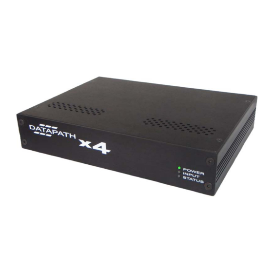
Page 4: Introduction
Introduction The Datapath x4 is a stand alone display wall controller that accepts a standard single or dual-link DVI input and can flexibly display this across four output monitors. Each output can be driven as DVI or analog RGB, and can represent an arbitrary crop region of the original input image. -
Page 5: Configuration Examples
Configuration Examples Listed on the next few pages are just a few examples of what can be achieved with the Datapath x4. The list of examples is not definative and users are encouraged to experiment with different display orientations. Duplicate the input signal x 4 and displays each duplicate on separate screens... - Page 6 Divide the input signal into quadrants and display each quarter on separate displays with optional frame rate conversion (in this case 30Hz to 60Hz). Crop regions can be adjusted to provide monitor bezel compensation. 18/10/2010...
- Page 7 Duplicate the input signal x2 and display 1 on a single landscape display and divide the 2nd into thirds, rotate to portrait, upscale and split between 3 displays. Crop input signal, upscale specific areas and display on 4 separate screens. 18/10/2010...
- Page 8 Crop the input signal into x4 and display x2 quarters landscape and x2 quarters portrait. Crop the input signal x4 rotate through 90º,180º or 270º, display in landscape and portrait. Arbitrary crop regions can allow the monitors to be artistically arranged, but maintain an undistorted image.
-
Page 9: Unpacking
We recommend that you do not discard the packing box until you are completely satisfied with the x4, and it is fully installed and working correctly. We also recommend that you make note of the serial number of the controller in a prominent place before you connect it to the computer. -
Page 10: Description
The output will still be displayed but not necessarily as expected. When the x4 device is connected to a PC by a USB cable, and the x4 Control application is active, then all three lights flash in turn to help to identify which unit is being controlled. -
Page 11: Rear Panel
USB Socket The USB socket is used to connect the x4 to a PC via a USB connection using the supplied USB Type A to Type B cable. Configuration of the x4 is programmable via an application utility allowing easy control of cropping, scaling, rotation and gaps. -
Page 12: Setting Up The X4
Ensure the power supply for the DVI source is disconnected. • Connect the cable from the DVI source to the input socket on the rear of the x4. • Connect the four displays to the output sockets on the rear panel of the x4. -
Page 13: Configuring The X4
Most graphics cards and HDMI appliances automatically select the “Preferred Mode” resolution and timings presented by the x4 EDID, but they may need to be forced to re-detect if the EDID contents are changed by the x4 application. This would typically be via a hot-plug event caused by disconnecting and reconnecting the DVI input cable. -
Page 14: Selecting The Regions To Be Displayed
1.0 (ie 1:1 or upscaled) in either direction. As an example it is possible to use the x4 to output four identical copies of the input signal (providing the resulting output timings remain within the capabilities of the single-link DVI outputs). -
Page 15: Operating Instructions
DVI-D cable is required. Configuring the x4 The x4 has a USB port to allow a host PC to connect to the x4 box and for the user to program its configuration. Once configured the x4 will run stand-alone without the need for the USB connection and will auto detect input resolutions and adjust internal scaling to drive the output monitors consistently. -
Page 16: X4 Control Application
The application will search for an x4 connected to your computer and display the status of the first x4 detected. Should there be more than one x4 in use, a list of all available x4’s can be found in the File menu. -
Page 17: Connection Diagram
Specific devices connected to your PC can be selected using the Select Device.. command on the File Menu. The x4’s will be listed by the USB Device or by a previously configured friendly name. - Page 18 The DVI-D Input group displays the current DVI mode that is being captured (if any) and the prefered mode that has been programmed into the x4’s EDID. Use the Modify button to update the EDID. The small square to the left of the current input resolution indicates whether the x4 has genlocked to the input source.
- Page 19 It may be necessary to force the graphics device in the host machine to detect the new modes, this can be done by selecting Detect on the Screen Resolutions dialog box (Windows® 7) or by disconnecting the souce from the x4 and reconnecting.
-
Page 20: Input Capture Regions
Input Capture Regions Each output of the x4 can select a different region of the input source image. This dialog (Fig. 9) displays the settings of each region (region 1 corresponds to output 1 etc). The numbers denote the top, left, width and height coordinates of the region that is to be displayed. -
Page 21: Monitor Outputs
The Monitor Outputs group shows the actual resolution and refresh rate that each of the four x4 outputs is currently providing. To see more information such as whether this is an analog RGB or DVI mode, if it is the monitor EDID preferred mode or a default mode programmed into the x4, along with detailed timing information, click on the Modify button for the required output. - Page 22 Fig.11 Individual monitor outputs can be configured by clicking on the corresponding Modify button. This will bring up a timing dialog similar to that of the input timings. This dialog is shown in Fig.12. Fig.12 18/10/2010...
- Page 23 Finally there is a Test button which should be used when defining a default mode that you are not sure the attached monitor can support. In test mode, the output timings are programmed, but they are not saved to non-volatile memory on the x4 until the OK button is pressed to accept the mode.
-
Page 24: Specification
Specification x4 Physical Dimensions 235 x 175 x 44mm/9.25” x 6.9” x 1.75” Operating Temperature Range 0 - 35 DegC/32 - 96 DegF 5V DC, 11W. Universal mains power adapter Power Requirements supplied (100-240V) The unit contains a cooling fan. The input and... -
Page 25: Datapath Limited
Datapath Limited make no representations or warranties with respect to the contents thereof, and do not accept liability for any errors or omissions. Datapath reserves the right to change specification without prior notice and cannot assume responsibility for the use made of the information supplied. - Page 26 UK Headquarters and Main Sales Office Datapath Limited Alfreton Road Derby, DE21 4AD Tel: +44 (0) 1332 294441 Fax: +44 (0) 1332 290667 Email: sales@datapath.co.uk Web: www.datapath.co.uk 18/10/2010...
-
Page 27: Index
Index Operating Temperature, 23 Cables, 3 Output, 15 Configuring DVI Input resolution, 13 output sockets, 12 Configuring the x4, 15 packing box, 9 Cooling, 23 Physical Dimensions, 23 CVT Reduced Blanking, 19 Power LED, 12 Datapath, 24 Power Requirements, 23... - Page 28 18/10/2010...
Need help?
Do you have a question about the X4 and is the answer not in the manual?
Questions and answers