
Related Manuals for Watchguard Firebox III 500


Summary of Contents for Watchguard Firebox III 500
- Page 1 Firebox III Hardware Guide Firebox 500, Firebox 700, Firebox 1000, Firebox 2500, Firebox 4500...
-
Page 2: Limited Hardware Warranty
PRODUCT, YOU AGREE TO THE TERMS HEREOF. If you do not agree to these terms, please return this package, along with proof of purchase, to the authorized dealer from which you purchased it for a full refund. WatchGuard Technologies, Inc. (”WatchGuard”) and you agree as follows: 1. - Page 3 2. Remedies. If any Product does not comply with the WatchGuard warranties set forth in Section 1 above, WatchGuard will, at its option, either (a) repair the Product, or (b) replace the Product; provided, that you will be responsible for returning the Product to the place of purchase and for all costs of shipping and handling.
- Page 4 Warranty. This is the entire agreement between WatchGuard and you relating to the Product, and supersedes any prior purchase order, communications, advertising or representations concerning the Product AND BY USING THE PRODUCT YOU AGREE TO THESE TERMS.
-
Page 5: Fcc Certification
FCC Certification FCC Certification This device has been tested and found to comply with limits for a Class A digital device, pursuant to Part 15 of the FCC Rules. Operation is subject to the following two conditions: Hardware Guide... -
Page 6: Industry Canada
This device must accept any interference received, including interference that may cause undesired operation. CE Notice The CE symbol on your WatchGuard Technologies equipment indicates that it is in compliance with the Electromagnetic Compatibility (EMC) directive and the Low Voltage Directive (LVD) of the European Union (EU). -
Page 7: Taiwanese Notice
Taiwanese Notice Taiwanese Notice VCCI Notice Class A ITE Hardware Guide... - Page 8 viii...
-
Page 9: Table Of Contents
Contents ..........ii Limited Hardware Warranty ............. v FCC Certification ............... vi CE Notice .............. vi Industry Canada ............vii Taiwanese Notice ..........vii VCCI Notice Class A ITE ........... 1 Hardware Requirements ............2 Hardware Description Firebox III front view (all models except Model 500 and 700) ...... -
Page 11: Hardware Requirements
Hardware Guide The WatchGuard Firebox III is a specially designed and optimized security appliance. Solid-state archi- tecture removes the risk of hard-drive failure and disk crashes. Three independent network interfaces allow you to separate your protected office network from the Internet while providing you an optional public interface for hosting Web, email, or FTP servers. -
Page 12: Hardware Description
The following minimum hardware requirements pertain to the management station–the computer that administers the Firebox. This computer runs the Firebox System Man- ager software, which provides access to WatchGuard Fire- box System applications. Hardware feature Minimum requirements (management station) -
Page 13: Firebox Iii Front View (All Models Except Model 500 And 700)
Hardware Description Firebox III front view (all models except Model 500 and 700) Indicators for the Firebox III Model 1000, Model 2500, and Model 4500 are on a central back-lit indicator panel. The following photograph shows the entire front view. The photograph below shows a close-up of the indicator panel. - Page 14 Armed Green light indicates the Firebox has been booted and is running. Sys A Indicates that the Firebox is running from its primary user-defined configuration. Sys B Indicates that the Firebox is running from the read- only factory default system area. Power Indicates that the Firebox is currently powered up.
-
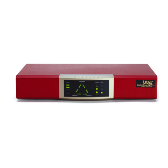
Page 15: Firebox Iii Front View (Model 500 And 700)
Hardware Description represents a load average of 0.15. The most significant load factor on a Firebox is the number of proxies running. Firebox III front view (Model 500 and 700) Firebox III Model 500 and 700 indicators are on a central back-lit indicator panel. -
Page 16: Firebox Iii Rear View (All Models Except Model 500 And 700)
Disarm Red light indicates the Firebox detected an error, shut down its interfaces, and will not forward any packets. Armed Green light indicates the Firebox has been booted and is running. Sys A Indicates that the Firebox is running from its primary user-defined configuration. - Page 17 Hardware Description AC Receptacle Accepts the detachable AC power cord supplied with the Firebox. Power Switch Turns the Firebox on or off. PCI Expansion Slot Reserved for future use. Factory Default This button is active only during the boot process. To boot the Firebox to SYS B, press this button and hold it down for 20-60 seconds (or until you see the Sys B light come on).
-
Page 18: Firebox Iii Rear View (Model 500 And 700)
there is a good physical connection to the Firebox. When the card runs at 10Mbit, the speed indicator is yellow. When the card runs at 100 Mbit, the speed indicator is green. The amber traffic indicator blinks when traffic is passing through the Firebox. -
Page 19: Physical Specifications (All Models Except Model 500 And 700)
Hardware Description Console Port Connects to the management station or modem through a serial cable supplied with the Firebox using PPP. Ethernet Jacks Indicators for each network interface display link status, card speed, and activity. The network interface connections (NICs) are auto-sensing and adapt to wire speed automatically. -
Page 20: Cross-Over Cabling
• 233 MHz AMD K6-II processor • 64-MB SDRAM • 8-MB flash disk • 100-240 VAC Autosensing, 50/60 Hz • Height: 2.85”; Width: 15.5 “; Depth: 10.5” Cross-over cabling To connect a Firebox to a hub or switch, use a standard, straight-through cable.
Need help?
Do you have a question about the Firebox III 500 and is the answer not in the manual?
Questions and answers