Bioness Ness H200 User Manual
Wireless
Hide thumbs
Also See for Ness H200:
- Clinicians manual (134 pages) ,
- User manual (98 pages) ,
- Troubleshooting manual (16 pages)
Table of Contents
Advertisement
Quick Links
Advertisement
Table of Contents
Troubleshooting

Related Manuals for Bioness Ness H200


Summary of Contents for Bioness Ness H200
- Page 1 User’s Guide...
- Page 2 , NESS H200 Wireless, Bioness, the Bioness Logo , and LiveOn are registered ® ® ® ® ® trademarks of Bioness Inc. in the United States or other countries | www.bioness.com Rx Only (US Only) ©2011 Bioness Inc. 612-00104-001 Rev. A...
- Page 3 User’s Guide Rx Only (US Only)
- Page 4 Disclaimer Bioness Inc and its affiliates shall not be liable for any injury or damage suffered by any person, either directly or indirectly, as a result of the unauthorized use or repair of Bioness Inc products. Bioness Inc does not accept any responsibility for any damage caused to its products, either directly or indirectly, as a result of use and/or repair by unauthorized personnel.
-
Page 5: List Of Symbols
List of Symbols Caution or Warning Double Insulated (Equivalent to Class II of IEC 536) Type BF Applied Part(s) Non-Ionizing Radiation Date of Manufacture Manufacturer This Product Must Not Be Disposed of with Other Household Waste Consult Instructions for Use Re-Order Number Lot Number Serial Number... - Page 6 User's Guide...
-
Page 7: Table Of Contents
Contents List of Symbols ....................III Chapter 1: Introduction ................. 1 Chapter 2: Device Description and Safety Information ..... 3 Device Description ..................... Indications for Use ..................... Contraindications ....................Warnings ......................Adverse Reactions .................... Precautions ......................Chapter 3: Environmental Conditions that Affect Use ....... 11 Radio Frequency (RF) Communication ............. - Page 8 Preparing Your Skin ................... 55 Wetting/Attaching the Cloth Electrodes ............. 56 Putting on the Orthosis ..................61 Chapter 9: Operating the NESS H200 Wireless System ....67 RF Communication Features ................67 Turning On the System ..................67 Turning Off the System ..................67...
- Page 9 Testing Stimulation in the Orthosis ..............68 Selecting a Stimulation Program ............... 69 Changing Stimulation Programs ................ 70 Turning On Stimulation ..................70 Pausing/Resuming Stimulation ................71 Using a Neuroprosthesis Program ..............72 Open Hand ....................72 Grasp and Release ..................73 Key Grip .......................
- Page 10 Chapter 12: Electronic Registration of Replacement Parts ....89 Registration Setup ..................... 90 Registration ....................... 92 Chapter 13: Troubleshooting ..............95 RF Communication Failure ................95 Frequently Asked Questions ................96 Quick Reference Troubleshooting ..............101 Chapter 14: Technical Specifications ..........105 Chapter 15: Appendix - EMI Tables ............
-
Page 11: Chapter 1: Introduction
The NESS H200 Wireless System delivers electrical stimulation to the nerves of the muscles that control the hand. The NESS H200 Wireless System may help to improve hand function and assist with tasks of daily living. - Page 12 User's Guide...
-
Page 13: Chapter 2: Device Description And Safety Information
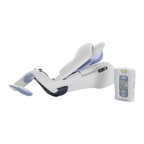
Chapter Device Description and Safety Information Device Description The NESS H200 Wireless System consists of an Orthosis and a wireless handheld Control Unit. See Figure 2-1. H200 Wireless Control Unit H200 Wireless Orthosis Figure 2-1: H200 Wireless Orthosis and Control Unit. -
Page 14: Indications For Use
Start, stop, and pause a stimulation program. • Communicate Control Unit battery status, RF communication errors, and Control Unit hardware/software malfunctions. Indications for Use The NESS H200 Wireless System is an electrical stimulation device indicated for the following uses: • Functional Electrical Stimulation (FES). •... -
Page 15: Contraindications
• Do not use the NESS H200 Wireless System on an arm where a regional disorder, such as a fracture or dislocation, would be adversely affected by motion from the stimulation. -
Page 16: Adverse Reactions
• Do not attempt to repair or modify the NESS H200 Wireless System. • If the H200 Wireless Orthosis overheats, turn off stimulation and remove the Orthosis. • If stimulation cannot be turned off using the H200 Wireless Control Unit or the trigger button on the H200 Wireless Orthosis, remove the Orthosis to stop stimulation. -
Page 17: Precautions
• Use caution if you have suspected or diagnosed epilepsy. • Talk to your doctor before using the NESS H200 Wireless System if you have any one of the following medical conditions in the affected arm: • Local insufficiency (insufficient blood flow). - Page 18 • Turn off the NESS H200 Wireless System before putting on or taking off the Orthosis. Do not turn on the NESS H200 Wireless System until the Orthosis is on the arm and the wing is closed.
- Page 19 • Use only H200 Wireless cloth electrodes supplied by Bioness Inc. • Do not use the NESS H200 Wireless System without the cloth electrodes. • Be sure the H200 Wireless cloth electrodes are wet and securely attached to the electrode bases before use.
- Page 20 If skin irritation or a skin reaction occurs, stop using your H200 Wireless System immediately. Contact your clinician or dermatologist, and your local distributor. Resume use only when the skin is completely healed. Then follow a skin conditioning protocol per the recommendation of your health-care specialist.
-
Page 21: Chapter 3: Environmental Conditions That Affect Use
Environmental Conditions that Affect Radio Frequency (RF) Communication Several components of the NESS H200 Wireless System communicate via radio communication. They have been tested and found to comply with the limits for a Class B digital device, pursuant to Part 15 (RF Devices) of the FCC (Federal Communications Commission) rules. - Page 22 Portable and mobile RF communications equipment can affect the NESS H200 Wireless System. Conformity Certification The NESS H200 Wireless System complies with Part 15 of the FCC rules. Operation is subject to the following two conditions: 1. This device may not cause harmful interference.
-
Page 23: Travel And Airport Security
H200 Wireless System. The NESS H200 Wireless System will likely set off the security alarm. Be prepared to remove the NESS H200 Wireless System so that security can scan it, or ask for the system to be scanned if you do not want to remove it. -
Page 24: Electromagnetic Compatibility
Electrotechnical Committee (IEC) 60601-1-2. The tables in the Appendix provide information regarding the EMC testing and guidance for safe use of the system. The NESS H200 Wireless System should be configured and used in accordance with the instructions provided in this guide. - Page 25 Committee on Radio Interference, International Electrotechnical Commission) emission requirements. • Do not use the NESS H200 Wireless System within three feet of short wave or microwave therapy equipment. Such equipment may produce instability in the stimulation output by the H200 Wireless Orthosis.
- Page 26 User's Guide...
-
Page 27: Chapter 4: H200 Wireless System Kit
Chapter H200 Wireless System Kit Contents • H200 Wireless Orthosis • H200 Wireless Control Unit • System Charger Set • Control Unit Neck Strap • Control Unit Wrist Strap • Control Unit Belt Pouch • Orthosis Wrist Strap • H200 Wireless Cloth Electrodes •... - Page 28 Orthosis Wrist Strap Cloth Electrode System Charger Set Mesh Bag Regular Large H200 Wireless Cloth Electrodes Control Unit Neck Strap Control Unit Wrist Strap Control Unit Belt Pouch User's Guide...
-
Page 29: H200 Wireless Orthosis
H200 Wireless Orthosis The Orthosis is available in right and left configurations, and in three sizes: small, medium, and large. H200 Wireless Control Unit The Control Unit communicates wirelessly with the Orthosis to control the Orthosis and monitor system status. System Charger Set The system charger set is for charging the Control Unit and Orthosis. -
Page 30: Cloth Electrode Mesh Bag
The cloth electrode mesh bag is for storing the H200 Wireless cloth electrodes. The mesh bag allows the cloth electrodes to air dry. CAUTION: Do not use the NESS H200 Wireless System without the cloth electrodes. CAUTION: The H200 Wireless cloth electrodes must be replaced every two weeks or sooner if they become damaged. -
Page 31: Chapter 5: H200 Wireless Orthosis
Chapter H200 Wireless Orthosis The Orthosis generates the electrical stimulation used to open and close your hand and move your thumb. The Orthosis has an integrated radio frequency stimulation unit and five stimulating electrodes. See Figure 5-1. The Orthosis responds to wireless signals from the Control Unit to turn stimulation on and off, and to adjust the stimulation intensity level. - Page 32 The H200 Wireless Orthosis features: See Figure 5-2. • A flexor support. • An extensor wing. • A spiral end. • A status light. • A stimulation light. • Audio alerts. • A rechargeable battery and charging port. Extensor Wing Stimulation Light Status...
-
Page 33: Orthosis Flexor Support
Orthosis Flexor Support The flexor support is designed to support your forearm while delivering electrical stimulation to the nerves of the muscles that flex your hand. The flexor support includes two electrode bases: #4 and #5. See Figure 5-3. Electrode Base #4 Electrode Base #5 Flexor Support... - Page 34 If you have a small wrist, your clinician may have fit an FPL panel to the Orthosis flexor support. The FPL panel fills excess space in the region of the #5 electrode base. See Figure 5-4. FPL Panel Electrode Base #5 Figure 5-4: Orthosis flexor support with an FPL panel.
-
Page 35: Orthosis Extensor Wing
Orthosis Extensor Wing The extensor wing delivers electrical stimulation to the nerves of the muscles that extend your hand. The extensor wing features: • Two electrode bases: #1 and #2. See Figure 5-5. • A wing release handle. • A wing arm. Extensor Wing Wing Arm... -
Page 36: Wing Release Handle
Wing Release Handle The wing release handle is used to open the extensor wing. See Figure 5-6. When the wing release handle and wing arm are squeezed together, the extensor wing lifts open. Extensor Wing Arm Wing Wing Release Handle Figure 5-6: Orthosis wing release handle. -
Page 37: Wing Arm
Wing Arm The wing arm is used to close the extensor wing. See Figure 5-7. When the wing arm is pushed down, the extensor wing clicks. The extensor wing is sufficiently closed when no more clicking can be heard. Extensor Wing Wing Arm Figure 5-7: Orthosis wing arm. -
Page 38: Spiral End Of The Orthosis
Spiral End of the Orthosis The spiral end of the Orthosis supports the hand. It also delivers stimulation to the nerves of the muscles that move the thumb. The spiral end features: See Figure 5-8. • A thenar. • A wrist bridge. •... -
Page 39: Thenar
See Figure 5-9. Snap for Thenar Cloth Electrode Figure 5-9: The thenar (inset) and placement of the thenar. CAUTION: Do not operate the NESS H200 Wireless System without a thenar cloth electrode in place. Chapter 5 - H200 Wireless Orthosis... -
Page 40: Wrist Bridge
Wrist Bridge The wrist bridge wraps around the back of your wrist. See Figure 5-10. The wrist bridge: • Stabilizes the Orthosis on your hand. • Supports your wrist in an extended position. • Helps to keep your wrist extended during finger opening and closing. The wrist bridge has a cushioned wrist insert on the underside to keep the H200 Wireless Orthosis positioned against your wrist. -
Page 41: Trigger Button
Trigger Button The trigger button is used to turn on/pause stimulation. See Figure 5-11. The trigger button works like the trigger button on the Control Unit. Note: If the trigger button on your Orthosis is disabled, consult your clinician. Trigger Button Figure 5-11: The H200 Wireless Orthosis trigger button. -
Page 42: Wrist Strap Attachment Ring
Wrist Strap Attachment Ring The wrist strap attachment ring is for hooking the Orthosis wrist strap to the Orthosis. See Figure 5-12. Orthosis Wrist Wrist Strap Strap Hook Attachment Ring Figure 5-12: Hooking the Orthosis wrist strap to the attachment ring. User's Guide... -
Page 43: Wrist Strap Attachment Bar
Wrist Strap Attachment Bar The wrist strap attachment bar is for securing the Orthosis wrist strap around the wrist. See Figure 5-13. Orthosis Wrist Wrist Strap Strap Attachment Bar Figure 5-13: Securing the Orthosis wrist strap. Chapter 5 - H200 Wireless Orthosis... -
Page 44: Status Light
Status Light The status light communicates system status and error messages. See Table 5-1. Stimulation Light The stimulation light communicates whether stimulation is on, off, or paused. See Table 5-1. Note: The illustrations in Table 5-1 are for a left H200 Wireless Orthosis. User's Guide... - Page 45 Left Orthosis Display Description Definition FLASHES GREEN System On FLASHES YELLOW Low Battery ALTERNATELY Status Light FLASHES YELLOW Battery Charging and GREEN Battery Fully SOLID GREEN Charged; Registration Successful Faulty Electrode FLASHES RED Contact Hardware/Software SOLID RED Error; Charging Error Stimulation SOLID YELLOW Stimulation Paused...
-
Page 46: Audio Alerts
Audio Alerts The Orthosis will beep when: • The NESS H200 Wireless System is turned on/off. • The Orthosis stimulation unit malfunctions. • Stimulation is turned on/off or paused. • There is a faulty electrode contact. • The battery charge level is low. -
Page 47: Rechargeable Battery And Charging Port
Rechargeable Battery and Charging Port The Orthosis has a rechargeable battery. The charging port is located at the back of the Orthosis. See Figure 5-14. Charging Port Figure 5-14: H200 Wireless Orthosis charging port. Chapter 5 - H200 Wireless Orthosis... - Page 48 User's Guide...
-
Page 49: Chapter 6: H200 Wireless Control Unit
Adjust the stimulation intensity level. • Monitor system status. • Mute system audio alerts. The Control Unit is powered by a single rechargeable NiMH AAA battery. CAUTION: Use only a battery supplied by Bioness Inc. Chapter 6 - H200 Wireless Control Unit... -
Page 50: Operating Buttons
Operating Buttons The Control Unit has eight operating buttons. See Table 6-1, Figure 6-1, and Table 6-2. Operating Description Function Button On/Off Button Turns On/Off the System Trigger Button Turns On/Off and Pauses Stimulation Intensity Increases Stimulation Intensity Adjustment Buttons Decreases Stimulation Intensity Mutes/Un-Mutes the Control Unit and H200 Mute Button... - Page 51 On/Off Button Mute Button Trigger Button Program 1 Button Program 2 Button Intensity Adjustment Stimulation Buttons Test Button Figure 6-1: Operating buttons. Visual Description Definition Display On/Off Button FLASHES GREEN System On Trigger Button FLASHES YELLOW Stimulation On RAPIDLY Trigger Button is SOLID YELLOW Stimulation Paused Table 6-2: Operating buttons: visual displays.
-
Page 52: Indicators And Digital Display
Indicators and Digital Display The Control Unit front panel features: • A Control Unit status indicator: • An RF communication indicator: • Program 1 and Program 2 selection indicators: • A digital display. See Figure 6-2. Control Unit Status RF Communication Indicator Indicator Program 1 Indicator... - Page 53 The Control Unit indicators show: • Control Unit status. • Stimulation program selected. • Control Unit low battery. • RF communication status. See Table 6-3. Indicator Description Definition Control Unit Status Indicator Low Battery, H200 Wireless FLASHES YELLOW Control Unit Control Unit Charging Error;...
- Page 54 The Control Unit digital display shows: • Stimulation intensity level: 0–9. • Electronic registration status. • Battery charging status. See Table 6-4. Display Description Definition Stimulation Intensity Level; 0–9 "0" Equals No Stimulation Alternating GREEN Arches Registration in Process Letter "C" Registration Complete Letter "E"...
-
Page 55: Audio Alerts
The H200 Wireless Control Unit beeps to indicate: • Electronic registration was initiated, successful, or unsuccessful. • The NESS H200 Wireless System was turned on/off. • A program has ended and stimulation has stopped. • An Control Unit hardware/software error occurred. -
Page 56: Charging Port
Charging Port The Control Unit charging port is located at the bottom of the Control Unit, under the flexible cover. See Figure 6-3. Note: Next to the charging port is the signal input/output port for the clinician's programmer. Signal Input/ Output Port Charging Port... -
Page 57: Chapter 7: H200 Wireless Stimulation Programs
Chapter H200 Wireless Stimulation Programs The NESS H200 Wireless System supports Functional Training, Neuroprosthesis, and Motor Neuromodulation programs designed to open and close the hand. Functional Training programs are designed to exercise your hand. They consist of repetitive opening and/or closing motions with a relaxation pause between each motion. - Page 58 User's Guide...
-
Page 59: Chapter 8: Setup Instructions
Charging the NESS H200 Wireless System It is important to charge your H200 Wireless System daily and for at least four hours before a fitting/programming session. Bioness recommends charging the Control Unit and the Orthosis at the same time. To charge the NESS H200 Wireless System: 1. - Page 60 2. Slide the selected blade into the system charger. See Figure 8-2. System Blade Charger Figure 8-2: Sliding the blade into the system charger. CAUTION: Use only the charger included in your H200 Wireless System Kit. Use of any other charger could damage the system. User's Guide...
- Page 61 3. Connect the Y cable to the charging ports of the Orthosis and Control Unit. The Control Unit charging port is under the flexible cover. See Figure 8-3. Charging Port Flexible Cover Y Cable Charging Port Interchangeable System Blade Charger Figure 8-3: Charging setup.
- Page 62 4. Plug the system charger into a power outlet. 5. If the Control Unit is charging, a rotating GREEN circle will appear in the Control Unit digital display. See Table 8-1. Control Unit Description Definition Display Rotating GREEN Circle in Battery Charging Digital Display Horizontal GREEN Line in...
- Page 63 6. If the Orthosis is charging, the status light on the Orthosis will ALTERNATELY FLASH YELLOW and GREEN. See Table 8-2. Orthosis Description Definition Display Status Light ALTERNATELY FLASHES YELLOW and Battery Charging GREEN Status Light is SOLID GREEN Battery Fully Charged Table 8-2: H200 Wireless Orthosis charging displays: left Orthosis.
-
Page 64: Checking The System Components
Checking the System Components Before using your H200 Wireless System: • Visually inspect the Orthosis and Control Unit for signs of damage. • The cloth electrodes must be replaced every two weeks. If the cloth electrodes are old or damaged discard them. Open a new set of cloth electrodes. -
Page 65: Preparing Your Skin
Before putting on your Orthosis, always check your skin for signs of irritation. If any irritation is present, do not put on the Orthosis and contact your clinician. Wait for complete healing before using the NESS H200 Wireless System. For optimal stimulation, the skin under the Orthosis should be clean and healthy. -
Page 66: Wetting/Attaching The Cloth Electrodes
Wetting/Attaching the Cloth Electrodes 1. Make sure the H200 Wireless System is turned off. 2. Place the Control Unit where it cannot be splashed. 3. Wet the cloth electrodes until they are saturated. See Figure 8-4. Figure 8-4: Wetting the cloth electrodes. CAUTION: Before wetting the cloth electrodes, always remove them from the Orthosis. - Page 67 If the cloth electrodes dry out, your response to the stimulation may change. If you need to adjust stimulation intensity more often than usual, try rewetting the cloth electrodes. CAUTION: Use only cloth electrodes supplied by Bioness Inc. Chapter 8 - Setup Instructions...
- Page 68 5. Match each cloth electrode to its corresponding electrode base. See Figure 8-6. Electrodes Base #1 Electrode Base #2 Electrode Base #3 (Thenar) Electrode Base #5 Electrode Base #4 Figure 8-6: Electrode bases #1–#5. User's Guide...
- Page 69 6. Snap cloth electrode #3 to the thenar. Note: The #3 large cloth electrode is for large thenars. 7. For cloth electrodes #1, 2, 4, and 5, face the white dot on the cloth electrode toward the electrode base. Insert the corners of the cloth electrode into the electrode base.
- Page 70 8. Check that each cloth electrode is securely attached to its corresponding electrode base. See Figure 8-8. Figure 8-8: Cloth electrodes in place on the Orthosis. CAUTION: Do not wear the Orthosis without the cloth electrodes. User's Guide...
-
Page 71: Putting On The Orthosis
Putting on the Orthosis Make sure you are sitting upright and centered (not leaning to one side). Your arm should be comfortable and your shoulder relaxed. To put on the Orthosis: 1. Position the Orthosis on a stable surface, and place your hand in the spiral end of the Orthosis. - Page 72 2. Position the Orthosis wrist bridge comfortably on the back of your wrist. See Figure 8-10. Wrist Bridge Figure 8-10: Positioning the wrist bridge. WARNING: Do not turn on stimulation until your Orthosis is completely set up and correctly attached to your arm. User's Guide...
- Page 73 3. Place your forearm in the Orthosis flexor support. See Figure 8-11. Flexor Support Figure 8-11: Positioning the flexor support. Chapter 8 - Setup Instructions...
- Page 74 4. Place your hand on top of the wing arm and grasp under the extensor wing with your fingers. 5. Pull the extensor wing out while pushing down on the wing arm. See Figure 8-12. Push down until no more clicking can be heard. Extensor Wing Wing Arm Wing Release Handle...
- Page 75 6. Attach the hook on the Orthosis wrist strap to the wrist strap attachment ring. See Figure 8-13. Wrist Strap Wrist Strap Hook Attachment Ring Figure 8-13: Attaching the Orthosis wrist strap. Chapter 8 - Setup Instructions...
- Page 76 7. Bring the wrist strap under the wrist. Make sure the cushion on the wrist strap is touching the wrist. 8. Pull the wrist strap up and through the wrist strap attachment bar. See Figure 8-14. Wrist Strap Wrist Strap Attachment Bar Cushion Figure 8-14: Attaching the wrist strap.
-
Page 77: Chapter 9: Operating The Ness H200 Wireless System
Chapter Operating the NESS H200 Wireless System RF Communication Features The Control Unit and Orthosis must be within RF communication range to communicate wirelessly. The communication range is approximately 3 meters. If RF communication fails, the RF communication indicator on the H200... -
Page 78: Testing Stimulation In The Orthosis
Testing Stimulation in the Orthosis stimulation test button is for testing whether the Orthosis is positioned correctly on the arm. The button is located on the side of the Control Unit. See Figure 9-1. To test stimulation in the Orthosis: 1. -
Page 79: Selecting A Stimulation Program
Selecting a Stimulation Program To select Program 1 : Turn on the system. Program 1 is selected automatically. When Program 1 is selected, the Program 1 indicator will be GREEN. To select Program 2 : 1. Turn on the system. 2. -
Page 80: Changing Stimulation Programs
Changing Stimulation Programs 1. Press the trigger button to pause stimulation. 2. Press the Program 1 or Program 2 button. Starting Stimulation Press the trigger button on the Control Unit or the trigger button on the Orthosis. Stimulation will turn on. •... -
Page 81: Pausing/Resuming Stimulation
Pausing/Resuming Stimulation Functional Training and Motor Neuromodulation Programs may be programmed to run from 5 minutes to 120 minutes, as determined by your clinician. Personal Custom Programs may be programmed to run from 30 to 240 minutes, as determined by your clinician. Once started, these programs will continue until they are finished. -
Page 82: Using A Neuroprosthesis Program
Using a Neuroprosthesis Program Your clinician may have assigned a Neuroprosthesis Program to the Program 1 or Program 2 button on your Control Unit. Neuroprosthesis programs are used to perform a specific task. There are three types of Neuroprosthesis Programs: Open Hand, Grasp and Release, and Key Grip. Open Hand To use Open Hand: 1. -
Page 83: Grasp And Release
Grasp and Release To use Grasp and Release: 1. Press the Control Unit trigger button or Orthosis trigger button to start stimulation. Your hand will open. 2. While your hand is open, place it next to the object you want to grasp. 3. -
Page 84: Key Grip
Key Grip To use Key Grip: 1. Press the Control Unit trigger button or Orthosis trigger button to start stimulation. Your fingers will close and your thumb will open. There should be a gap between your thumb and the side of your index finger. 2. -
Page 85: Adjusting Stimulation Intensity
Adjusting Stimulation Intensity Each time you turn on your Control Unit, the stimulation intensity level will be “5." If necessary, you can adjust the stimulation intensity level when in standby mode or when stimulation is on. To adjust stimulation intensity: 1. -
Page 86: Muting/Un-Muting The System Audio Alerts
Muting/Un-Muting the System Audio Alerts Press the mute button briefly. The mute button is located on the side of the Control Unit. Audio alerts are listed in Table 9-1. Note: When the system is turned on the next time, the default volume setting will be restored. -
Page 87: Chapter 10: Removing The Orthosis
Chapter Removing the Orthosis To remove the Orthosis: 1. Press the Control Unit on/off button to turn off the H200 Wireless system. 2. Carefully unfasten the wrist strap and slide it away from the wrist strap attachment bar. See Figure 10-1. Wrist Strap Wrist Strap Attachment Bar... - Page 88 3. Pinch the wing release handle and wing arm together and open the extensor wing. See Figure 10-2. Wing Arm Wing Release Handle Figure 10-2: Opening the extensor wing. User's Guide...
- Page 89 4. With the extensor wing open (See Figure 10-3), remove the flexor support from under your forearm. Flexor Support Figure 10-3: Removing the flexor support. 5. Then lift the flexor support up and over your forearm, and remove the spiral end of the Orthosis from your hand. 6.
- Page 90 User's Guide...
-
Page 91: Chapter 11: Maintenance And Cleaning
Chapter Maintenance and Cleaning Daily Maintenance and Storage 1. Store the H200 Wireless cloth electrodes in the cloth electrode mesh bag or where they can air dry. 2. Check the system components for signs of wear and damage. 3. Replace any components that appear old, worn, or damaged. Contact your local distributor for assistance. -
Page 92: Battery Replacement: H200 Wireless Control Unit
Battery Replacement: H200 Wireless Control Unit The battery in the H200 Wireless Control Unit is a rechargeable AAA NiMH battery. It should be replaced approximately every two years. To replace the Control Unit battery (AAA NiMH 1.2 V): 1. Using a Phillips screwdriver, remove the screw from the battery cover on the back of the H200 Wireless Control Unit. -
Page 93: Battery Replacement: H200 Wireless Orthosis
Battery Replacement: H200 Wireless Orthosis The Orthosis has a rechargeable battery that can only be replaced by a Bioness authorized representative. If the battery needs to be replaced, contact your local distributor. Chapter 11 - Maintenance and Cleaning... -
Page 94: Cleaning
Cleaning General Instructions All H200 Wireless System Kit components may be cleaned as needed or weekly by carefully wiping them with a damp cloth. Use water. Do not use detergents or other cleaning agents, unless otherwise specified below. H200 Wireless electronic components are not waterproof. Do not immerse them in water. -
Page 95: Disinfecting
3. As needed, use additional saturated disinfectant wipes or cloths to keep the components surface wet for 3 minutes. Note: Be sure to follow the Bioness instructions for the specified contact time to ensure an effective bacteria kill. Chapter 11 - Maintenance and Cleaning... -
Page 96: Wrist Insert
3. As needed, use additional saturated disinfectant wipes or cloths to keep the components surface wet for 3 minutes. Note: Be sure to follow the Bioness instructions for the specified contact time to ensure an effective bacteria kill. Wrist Insert The wrist insert cannot be disinfected. -
Page 97: System Kit Carrying Case
System Kit Carrying Case The NESS H200 Wireless System Kit carrying case may be cleaned and low-level disinfected using CaviCide (Metrex, Orange, CA) or 70% isopropyl ® alcohol (IPA) per the following instructions: CaviCide: 1. Spray the entire surface of the System Kit carrying case with CaviCide. - Page 98 Note: Be sure to follow the Bioness instructions for the specified contact time to ensure an effective bacteria kill. Note: Do not use other cleaning/disinfecting agents such as a diluted bleach mixture, Lysol or Clorox wipes. Bioness has not tested these products' effectiveness on the H200 Wireless components.
-
Page 99: Chapter 12: Electronic Registration Of Replacement Parts
Chapter Electronic Registration of Replacement Parts The NESS H200 Wireless System Control Unit and Orthosis must be electronically registered to each other to communicate wirelessly. The components in your System Kit are electronically registered. When you purchase a replacement H200 Wireless Control Unit or Orthosis, the replacement component must be electronically registered to the existing component. -
Page 100: Registration Setup
Registration Setup 1. Verify that all H200 Wireless System components are turned off. 2. Place the components to be registered close together on a table, but not touching. See Figure 12-1. H200 Wireless Control Unit H200 Wireless Orthosis Figure 12-1: Place the components to be registered close together. 3. - Page 101 4. Locate the System ID Number (for example, A334) on the existing system component. The System ID Number is on the back of the H200 Wireless Control Unit and under the extensor wing of the H200 Wireless Orthosis. See Figure 12-2. System ID Number System ID Number Figure 12-2: Location of the System ID Numbers.
-
Page 102: Registration
5. Copy the System ID Number onto the blank label on the replacement system component. Registration 1. Simultaneously press and hold for three seconds the trigger button and the minus button on the H200 Wireless Control Unit. 2. Press the trigger button on the wrist bridge of the Orthosis. 3. - Page 103 5. When registration is complete: • (“C” for complete) will appear in the digital display. • Control Unit status light and the Orthosis status light will turn GREEN for a few seconds. • The Control Unit will beep. Note: If (“E”...
- Page 104 User's Guide...
-
Page 105: Chapter 13: Troubleshooting
FLASHES RED then turn the Control Unit off and back on. Reorient the Control Unit. • Check for obstructions or sources of interference. • Change the H200 Wireless cloth electrodes. • Contact the Bioness Client Relations Department. Chapter 13 - Troubleshooting... -
Page 106: Frequently Asked Questions
• After the components are fully charged, keep them connected to the system charger until ready to use. If I charge the NESS H200 Wireless System every day, will I harm the batteries? • No. Daily charging will not affect the lifespan or functionality of the batteries. - Page 107 • RF communication has failed. The Orthosis battery most likely is discharged. • Connect the system charger. (The NESS H200 Wireless System can be charged during operation.) When communication is restored, the RF communication indicator will stop flashing and the status light on the Orthosis will FLASH GREEN.
- Page 108 How will I know when the Orthosis battery charge level is low? • When the Orthosis battery charge level is low, the status light on the Orthosis will FLASH YELLOW and the Orthosis will beep. How will I know when the Control Unit battery charge level is low? •...
- Page 109 My hand is not moving satisfactorily, and the NESS H200 Wireless System is not indicating any errors. • The Orthosis may not be positioned correctly. • Turn off the Control Unit. • Make sure the cloth electrodes are wet and your hand/arm are clean.
- Page 110 The Orthosis status light and stimulation light are not lit. • A replacement component needs to be electronically registered to the existing component for the NESS H200 Wireless System to communicate wirelessly. • For instructions on how to register a replacement component, see "Electronic Registration of Replacement Parts."...
-
Page 111: Quick Reference Troubleshooting
After I fully charged the NESS H200 Wireless System, I disconnected the system charger and then immediately reconnected it. The charging indications appeared again on the Control Unit and Orthosis. Are the components fully charged or do I need to repeat the charging process? •... - Page 112 Control Description Definition Unit On/Off Button FLASHES GREEN System On Trigger Button FLASHES YELLOW Stimulation On RAPIDLY Trigger Button is SOLID YELLOW Stimulation Paused Stimulation Intensity Level; Displays 0–9 "0" Equals No Stimulation Alternating GREEN Arches Registration in Process Letter "C" Registration Complete Letter "E"...
- Page 113 Left Orthosis Display Description Definition FLASHES GREEN System On FLASHES YELLOW Low Battery ALTERNATELY Status Light FLASHES YELLOW Battery Charging and GREEN Battery Fully SOLID GREEN Charged; Registration Successful Faulty Electrode FLASHES RED Contact Hardware/Software SOLID RED Error; Charging Error Stimulation SOLID YELLOW Stimulation Paused...
- Page 114 User's Guide...
-
Page 115: Chapter 14: Technical Specifications
Chapter Technical Specifications H200 Wireless Control Unit Specifications Classification Internally powered, continuous operation Operation Modes User and Standby Battery Type Rechargeable AAA NiMH 1.2 V, 900–1100 mAh • On/Off illuminated button • Trigger illuminated button to turn on and pause stimulation •... - Page 116 H200 Wireless Orthosis Specifications Internally powered, continuous operation with type BF applied Classification parts Operating Voltage 3.7 V Proprietary rechargeable Li-Ion (Lithium Ion) 3.7 V, 280–350 Battery Type • H200 Wireless Orthosis status (fault, battery, charging) and Indications Stimulation LEDs •...
- Page 117 H200 Wireless Orthosis Specifications Small Medium Large Length: 270 mm Length: 270 mm Length: 300 mm Dimensions Width: 110 mm Width: 110 mm Width: 130 mm (closed) Depth: 90 mm Depth: 90 mm Depth: 130 mm Estimated Weight 300 grams 300 grams 300 grams H200 Wireless Orthosis Pulse Parameters...
- Page 118 H200 Wireless Orthosis Pulse Parameters Intensity (Peak) 0–80 mA, 1-mA resolution (positive phase) • Electrodes #1, #2, #3, #5: 13.1 mA rms Maximum Current Intensity (rms) • Electrode #4: 18.6 mA rms Max Voltage 120 V Symmetric Positive Pulse Duration (µsec) Negative Pulse Duration (µsec) Inter-Phase Interval (µsec) Max Total Pulse Duration...
- Page 119 Power Supply Specifications Use medical Class II safety approved power supply provided/approved by Bioness with the following ratings: Input Voltage 100–240 V AC Current 400 mA Frequency 50–60 Hz Output Voltage 5 V ± 5% Current 2400 mA Note: The H200 Wireless Control Unit and Orthosis can be used while charging if the Control Unit is not connected to the Clinician's Programmer.
- Page 120 H200 Wireless Cloth Electrode Specifications Non-woven cloth Material Note: Use only cloth electrodes provided by Bioness Inc. Cloth 3 Regular 3 Large Electrode # Area (mm 1784 1185 1284 2038 1185 Wireless Technology Description Wireless Link Specifications Frequency Band 2.4 GHz, ISM band Complies with FCC 15.247 (for U.S.)
-
Page 121: Chapter 15: Appendix - Emi Tables
Guidance and Manufacturer’s Declaration Electromagnetic Emissions The NESS H200 Wireless System is intended for use in the electromagnetic environment specified below. The customer or the user of the NESS H200 Wireless System should assure that it is used in such an environment. - Page 122 Equipment and Systems The NESS H200 Wireless System is intended for use in the electromagnetic environment specified below. The customer or the user of the NESS H200 Wireless System should assure that it is used in such an environment. Immunity Test...
- Page 123 If 70% U (30% dip in 70% UT (30% dip the user of the ) for 25 cycles in U ) for 25 cycles NESS H200 Wireless System <5% U (>95% dip <5% U (>95% dip requires continued in U...
- Page 124 Guidance and Manufacturer’s Declaration—Electromagnetic Immunity The NESS H200 Wireless System is intended for use in the electromagnetic environment specified below. The customer or the user of the NESS H200 Wireless System should assure that it is used in such an environment.
- Page 125 To assess the electromagnetic environment due to fixed RF transmitters, an electromagnetic site survey should be considered. If the measured field strength in the location in which the NESS H200 Wireless System is used exceeds the applicable RF compliance level above, the NESS H200 Wireless System should be observed to verify normal operation.
- Page 126 The NESS H200 Wireless System is intended for use in an electromagnetic environment in which radiated RF disturbances are controlled. The customer or the user of the NESS H200 Wireless System can help prevent electromagnetic interference by maintaining a minimum...
- Page 127 NOTE 1: At 80 MHz and 800 MHz, the higher frequency range applies. NOTE 2: These guidelines may not apply in all situations. Electromagnetic propagation is affected by absorption and reflection from structures, objects, and people. For transmitters rated at a maximum output power not listed above, the recommended separation distance d in meters (m) can be determined using the equation applicable to the frequency of the transmitter, where P is the maximum output power rating of the transmitter in watts (W) according to the transmitter manufacturer.
- Page 128 User's Guide...
Need help?
Do you have a question about the Ness H200 and is the answer not in the manual?
Questions and answers
Charging device H200
To charge the Bioness Ness H200 device:
1. Use only the charger included in the H200 Wireless System Kit.
2. Slide the correct blade into the system charger.
3. Connect the Y cable to both the Orthosis and the Control Unit charging ports.
- The Control Unit port is under a flexible cover.
4. Plug the system charger into a power outlet with dry hands.
Charging Indicators:
- Control Unit: Rotating green circle = Charging; Horizontal green line = Fully charged.
- Orthosis: Status light flashes yellow and green = Charging; Steady green = Fully charged; Flashes yellow = Low battery.
This answer is automatically generated