Table of Contents
Advertisement
Quick Links
Download this manual
See also:
User Manual
Advertisement
Table of Contents

Related Manuals for TallyGenicom 6800 Series


Summary of Contents for TallyGenicom 6800 Series
- Page 1 ® TallyGenicom 6800 Series Printers Administrator’s Manual...
-
Page 2: Restrictions
TallyGenicom disassemble the Software. or by TallyGenicom. If you fail to comply with the terms of this You agree to keep confidential and use your best License and such failure is not corrected within thirty (30) days efforts to prevent and protect the contents of the after notice. - Page 3 Administrator’s Manual ® TallyGenicom 6800 Series Printers...
-
Page 4: Trademark Acknowledgements
TallyGenicom makes no representations or warranties of any kind regarding this material, including, but not limited to, implied warranties of merchantability and fitness for a particular purpose. TallyGenicom shall not be held responsible for errors contained herein or any omissions from this... -
Page 5: Table Of Contents
Table of Contents 1 Introduction............11 Printer Overview ..................11 TallyGenicom 6800 Series Cartridge Ribbon Printers (CRP)... 11 Consumable Monitoring with PrintNet Enterprise ........13 Protocols and Emulations ............... 14 Taking Care of your Printer..............14 Conventions in this Manual..............14 Warnings and Special Information............ - Page 6 Table of Contents 4 Configuration Menus..........53 Configuration Overview ................53 Changing Parameter Settings ............53 Saving Parameter Settings .............. 54 Default and Custom Configurations ..........54 Navigating the Menus ..............54 Top Level Menu Overview ..............56 Changing Parameters Example ............57 Auto Save Configuration ..............
- Page 7 Table of Contents 5 Interfaces............125 Overview....................125 RS-232 Serial Interface ................127 USB ......................128 Centronics Parallel Interface..............129 Centronics Parallel Interface Signals ..........130 IEEE 1284 Parallel Interface..............131 Compatibility Mode.................131 Nibble Mode ...................131 Byte Mode ..................131 Signals ...................132 Ethernet ....................134 6 Reprogramming the Security Key....... 135 Reprogramming the Security Key............135 How to Program the Security Key ..........135 7 Downloading Firmware........
- Page 8 Table of Contents 8 Troubleshooting ..........161 Cleaning Requirements ................ 161 Exterior Cleaning................161 Interior Cleaning ................162 Diagnosing Problems................164 Bar Code Verification ..............164 Printing a Hex Dump ..............165 Most Frequent Problems and Solutions..........167 Diagnostics for EXX, BAD NVM, or ILL NVM Errors ......168 Fault Messages ................
- Page 9 Copying the QCMC “Snapshot” Image to a Second Printer ....217 F PTX_SETUP Commands ........219 Overview....................219 The PTX_SETUP Commands ..............219 Commands ..................220 G Customer Support..........227 TallyGenicom Customer Support Center..........227 TallyGenicom Supplies Department .............227 Corporate Offices..................228 H Communication Notices ........229 Notices....................229 Communication Statements..............232...
- Page 10 Table of Contents...
-
Page 11: Introduction
TallyGenicom® is pleased to announce the TallyGenicom 6800™ Series Line Matrix printers, the latest generation product from a long heritage of high quality extending over 30 years. TallyGenicom® is a global leader for design and manufacturing with the ability to deliver unsurpassed service and support. - Page 12 Chapter Printer Overview Table 1. 6800 Series Models and Configurations Configuration Print Speed Number Model Number (Lines per Minute) 6805 6805Z LMPPLS (Line Matrix Printer Pedestal Low Speed) 6810 1000 6810Z 1000 LMPCLS 6810Q 1000 (Line Matrix Printer Cabinet Low Speed)
-
Page 13: Consumable Monitoring With Printnet Enterprise
TallyGenicom 6800 Series Cartridge Ribbon Printers (CRP) Pedestal (68XX) • The pedestal model has a clamshell design that allows easy access to all controls providing faster ribbon replacements and easier paper loading. • Oversized casters are standard making movement easy. -
Page 14: Protocols And Emulations
Chapter Protocols and Emulations Protocols and Emulations A protocol is a set of rules governing the exchange of information between the printer and its host computer. These rules consist of codes that manipulate and print data and allow for machine-to-machine communication. A printer and its host computer must use the same protocol. -
Page 15: Warnings And Special Information
• 6800 Series Printers Emulations Applications Manual, Volume 1 Defines printer emulations. • 6800 Series Printers Fonts and Character Sets Applications Manual, Volume 3 Defines printer fonts and character sets. • 6800 Series Printers Graphics Languages Applications Manual, Volume 4... -
Page 16: Contact Information
(31) 24 6489 311 Asia Pacific (65) 6548 4114 China (86) 800-999-6836 http://www.tallygenicom.com/service/default.aspx TallyGenicom Supplies Department Contact the TallyGenicom Supplies Department for genuine TallyGenicom supplies. Americas (800) 733-1900 Europe, Middle East, and Africa (33) 1 46 25 19 07 Asia Pacific... -
Page 17: Corporate Offices
Phone: (65) 6542 0110 Fax: (65) 6546 1588 Printronix Commercial (Shanghai) Co. Ltd 22F, Eton Building East No.555, Pudong Av. Shanghai City, 200120, P R China Phone: (86) 400 886 5598 Fax: (86-21) 5138 0564 Visit the web site at www.tallygenicom.com... - Page 18 Chapter Contact Information...
-
Page 19: Setting Up The Printer
Setting Up The Printer Before You Begin Read this chapter carefully before installing and operating the printer. The printer is easy to install. However, for your safety and to protect valuable equipment, perform all the procedures in this chapter in the order presented. Power Requirements The printer must be connected to a power supply outlet that supplies 90 to 264 volts AC at its upper and lower limits. - Page 20 Chapter Select a Site • Is located within the maximum allowable cable length to the host computer. This distance depends on the type of interface you plan to use, as shown in Table 2. Table 2. Maximum Interface Connection Cable Length Interface Type Maximum Cable Length Centronics Parallel...
-
Page 21: Printer Dimensions
Printer Dimensions Printer Dimensions 37.73 in (95.8 cm) 11.36 in (28.9 cm) 6.1 in (15.5 cm) .75 in (1.9 cm) 25.92 in (65.8 cm) 19.1 in (73.9 cm) Figure 1. Tabletop Model... - Page 22 Chapter Printer Dimensions 57.5 in (146.1 cm) 41.0 in 27.0 in (104 cm) (68.6 cm) 29.0 in (73.7 cm) 27.0 in 83.0 in (68.6 cm) (210.8 cm) 27.0 in (68.6 cm) Figure 2. Cabinet Model 59.0 in 42.5 in (149.9 cm) (107.8 cm) 27.0 in (68.6 cm)
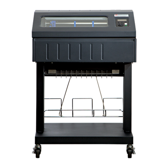
- Page 23 Printer Dimensions 29.5 in. (74.93 cm) 11.36 in. (28.9 cm.) 54.0 in. (137.2 cm) 25.92 in. 19.1 in. (65.8 cm) (48.5 cm) 29.1 in. (73.9 cm.) 184564 REV B Figure 4. Pedestal Model...
- Page 24 Chapter Printer Dimensions 54.0 in. (137.2 cm) 35.9 in. (91.2 cm) 6.5 in. (16.5 cm) 25.92 in. (65.8 cm) 19.1 in. (48.5 cm) 38.9 in. (98.8 cm) Figure 5. Enclosed Pedestal Model...
- Page 25 60.1 in. (152.7 cm) 42.0 in. (106.7 cm) 31.95 in. 25.92 in. (81.2 cm) 19.1 in. (65.8 cm) (43.8 cm) 38.9 in. (98.8 cm) Figure 6. Zero Tear Pedestal Model...
-
Page 26: Printer Component Locations
Chapter Printer Component Locations Printer Component Locations Ribbon Ribbon Cartridge Tab (2) Ribbon Tension Knob Tractor (2) Blue Tractor Splined Shaft Lock (2) Hammer Bank Paper Support (2) Cover and Ribbon Mask Tab Slot (2) Vertical Position Knob Platen Lever Platen Stop Ribbon Cartridge Interface... -
Page 27: Operating The Printer
Operating The Printer Powering on the Printer When you power on the printer, it executes a self-test. The default power-up state is offline. When the self-test completes and the software has initialized successfully, the status indicator light is off, indicating the printer is offline. When the printer is online, the default emulation type you have installed appears in LCD display. -
Page 28: The Control Panel
Chapter The Control Panel The Control Panel Figure 8 shows the keys, displays, and indicators as they appear on the control panel. The following section provides the descriptions, and functions of the control panel keys. Key combinations are indicated with the plus (+) sign. For example, “Press ... -
Page 29: Control Panel Keys
Control Panel Keys Control Panel Keys ONLINE Toggles the printer between online and offline modes. The key performs the following in Online, Offline, Fault, and Menu modes: • Online Mode – sets the printer to Offline Mode. • Offline Mode – sets the printer to Online Mode. •... - Page 30 Chapter The Control Panel • Eject Function — For pedestal models only, if the View key is pressed for a long time (more than 1/2 second), the bottom of the last printed form will move to the tear bar position as set by the Tear Bar Dist menu. The message "READY TO TEAR/EJECT To Return"...
- Page 31 Control Panel Keys ↵ ENTER ( When navigating the configuration menus, the Enter key (referenced by the symbol ↵ ) selects the currently displayed option value as the active value. An asterisk (*) appears next to the active value on the display. ENTER is also used for starting and stopping printer tests and generating a configuration printout.
-
Page 32: Cancel A Print Job
Chapter The Control Panel PREV + NEXT ( + ) When both keys are pressed simultaneously, the printer will reset to the power-up configuration and reset its internal state (in offline mode). Ribbon Life Indicator If the Panel Display menu is set to Ribbon Life, the bottom of the LCD displays the remaining life of the currently installed ribbon. -
Page 33: Operational Procedures
Reload Paper Operational Procedures This section contains routine printer operating procedures on how to: • reload paper • unload paper. Reload Paper Do this procedure when “LOAD PAPER” displays. (This message occurs when the last sheet of paper passes through the paper slot.) This procedure reloads paper without removing the last sheet of the old paper supply, while retaining the current top-of-form setting. - Page 34 Chapter Operational Procedures Upper Paper Guide Wire Guide (2) Paper Slot Zero Tear Pedestal Model Figure 9. Paper Slot Location (continued) 1. Raise the printer cover. Raise the platen lever as far as it will go. (See Figure 7 on page 26 for the location of the lever.) NOTE: Do not open tractor doors or remove the existing paper.
- Page 35 Reload Paper New Paper Existing Paper Figure 10. Loading New Paper into the Printer 6. Pull the new paper above and behind the ribbon mask, but in front of the existing paper. See Figure 7 on page 26 for the ribbon mask location. If necessary, gently press the existing paper back.
- Page 36 Chapter Operational Procedures Vertical Position Knob Paper Thickness Indicator Platen Stop Platen Lever Platen Stop Knob 183444 REV B Figure 11. Setting the Platen Lever 9. Turn the platen stop knob clockwise or counterclockwise to match the paper thickness. (The A-B-C scale corresponds approximately to 1-, 3-, and 6-part paper thickness).
- Page 37 Reload Paper NOTE: Perform steps 15 to 31 only if you are unable to load the new paper over the existing paper. 15. Open both tractor doors. 16. Remove the old paper from the tractors. Allow the paper to fall into the paper supply area.
- Page 38 Chapter Operational Procedures Tractor Paper Tractor Splined Shaft Tractor Lock Paper Scale Figure 13. Positioning the Left Tractor to Avoid Damage CAUTION To avoid damage to the printer caused by printing on the platen, always position the left tractor unit directly to the left of the “1” mark on the paper scale.
- Page 39 Reload Paper Tractor Door Tractor Lock Figure 14. Loading Paper onto the Sprockets 22. Unlock the right tractor. 23. Load the paper onto the sprockets and close the tractor door. If necessary, slide the right tractor to remove paper slack or to adjust for various paper widths.
- Page 40 Chapter Operational Procedures Upper Paper Guide Upper Paper Guide Metal Paper Guide (2000 lpm only) Paper Slot Paper Slot Tabletop Model Cabinet Model 184737 REV A Upper Paper Upper Paper Guide Guide Wire Wire Guide (2) Guide (2) Paper Paper Slot Slot Pedestal Model Enclosed Pedestal Model...
- Page 41 Reload Paper Upper Paper Guide Wire Guide (2) Paper Slot Zero Tear Pedestal Model Figure 15. Using the Paper Guide to Orient the Paper (continued) 24. Tabletop, Pedestal, or Zero Tear Pedestal models: Using the vertical position knob to move the paper up, guide the paper over the upper paper guide and through the slot to the rear of the top cover.
- Page 42 Chapter Operational Procedures TOF Indicator Perforation Vertical Position Knob Figure 16. Aligning the Perforation with the TOF Indicator 27. Align the top of the first print line with the TOF indicator on the tractor by rotating the vertical position knob. For best print quality, it is recommended that the top-of-form be set at least one print line or more below the perforation.
- Page 43 Reload Paper Vertical Position Knob Paper Thickness Indicator Platen Stop Platen Lever Platen Stop Knob 183444 REV B Figure 17. Adjusting the Platen Lever 28. Turn the platen stop knob clockwise or counterclockwise to match the paper thickness. (The A-B-C scale corresponds approximately to 1-, 3-, and 6-part paper thickness.
-
Page 44: Unload Paper
Chapter Operational Procedures Unload Paper 1. Press ONLINE to place the printer in offline mode and open the printer cover. 2. For cabinet models, open the cabinet rear door. For models with the power stacker installed, press the STACKER UP key on the rear control panel. - Page 45 Integrated Print Management Unload Paper Paper Power Stacker Figure 19. Removing Stacked Paper from the Printer 6. For cabinet models, remove the stacked paper from the rear cabinet floor. For cabinet models with the power stacker installed, remove the paper from the wire paper tent and press the STACKER DOWN key to lower the stacker mechanism.
- Page 46 Chapter Operational Procedures Tractor Door Platen Lever Figure 20. Completely Removing the Paper 8. To completely remove the paper from the printer: a. Raise the platen lever as far as it will go and open both tractor doors. CAUTION Be careful when pulling any paper backward through the paper path, especially when using a label stock.
-
Page 47: Integrated Print Management System
Output Darkness Integrated Print Management System The 6800 CRP has a feature that automatically monitors and communicates the status of the ribbon life to help the operator know when to change ribbons. Using an ink delivery system called the Cartridge Ribbon System (CRS), the printer can automatically detect when a new or used ribbon is loaded, and all ribbon properties. -
Page 48: Loading A Used Ribbon Cartridge
Chapter Integrated Print Management System Loading a Used Ribbon Cartridge You can take the ribbon cartridge off the printer and reload it at a later time. The ribbon life gauge automatically updates to reflect the correct remaining capacity. NOTE: Since the ribbon usage information is stored on the ribbon cartridge, you can reload a partially used cartridge onto a different printer. -
Page 49: Changing Ribbon Cartridge
Changing Ribbon Cartridge Changing Ribbon Cartridge Before changing the ribbon cartridge, determine whether at the end of ribbon life, you want to make the print lighter (extend the ribbon life) or darker (shorten the ribbon life). If you want to make the print lighter or darker, go to “Ribbon End Point”... - Page 50 Chapter Integrated Print Management System Ribbon Ribbon Tab (2) Cartridge Ribbon Tension Knob Tab Slot (2) Air Shroud Assembly Figure 22. Installing the Ribbon Cartridge 5. Remove the ribbon slack on the new ribbon cartridge by turning the ribbon tension knob clockwise. CAUTION Do not turn the ribbon tension knob counterclockwise.
- Page 51 Changing Ribbon Cartridge Ribbon Cartridge Ribbon Mask Hammerbank Cover Ribbon Ribbon Tension Knob Ribbon Cartridge Figure 23. The Ribbon Cartridge Snapped in Place 7. Rock the cartridge downward, making sure that the ribbon goes between the guide and the mask (see Figure 23). You will feel it snap into place. CAUTION Make sure that the ribbon does not twist or fold over.
- Page 52 Chapter Integrated Print Management System...
-
Page 53: Configuration Menus
Configuration Menus Configuration Overview To print data, the printer must respond correctly to signals and commands received from the host computer. Configuration is the process of matching the printer's operating characteristics to those of the host computer and to specific tasks, such as printing labels or printing on different sizes of paper. The characteristics which define the printer's response to signals and commands received from the host computer are called configuration parameters. -
Page 54: Saving Parameter Settings
Chapter Configuration Overview Saving Parameter Settings The parameter settings that you have changed can be permanently stored in the printer’s memory as a configuration. See “Auto Save Configuration” on page 60. and “Saving Your New Configuration” on page 61. You may also save your new configurations using the PTX_SETUP command host control code. - Page 55 Navigating the Menus Press to scroll through the available choices for the highlighted menu. If the highlighted menu contains submenus, these buttons have no effect and the ↵ message “ for Submenu” will display. Press to confirm selection. For normal menus, this will ENTER change or execute the menu.
-
Page 56: Top Level Menu Overview
Chapter Top Level Menu Overview Top Level Menu Overview When entering Menu mode, the user will see top level menus represented as icons as shown below. Use the navigation buttons up, down, right, and left to highlight the desired icon. As the user navigates, the name of the top level menu displays on the top line of the LCD. -
Page 57: Changing Parameters Example
Changing Parameters Example Changing Parameters Example OFFLINE * = Factory Default Quick Operator Setup Menu Font Forms Length Length Unidirectional . . . (lines) (inches) Disable* (1-255) (0.1-25.5) Enable A configuration consists of several parameters. The default factory configuration has a starting set of parameters. In the configuration menu above, and in all the configuration menus in this chapter, the factory default values are indicated by an asterisk (*). - Page 58 Chapter Top Level Menu Overview Step Press Notes Make sure the printer is on. ONLINE Press to enter Menu mode. ENTER UNTIL ENTER UNTIL The * indicates this choice is active. ENTER Press until the desired selection or value displays.
- Page 59 Changing Parameters Example Step Press Notes The * indicates this choice is active. ENTER Press ENTER to go back into the menus or press ONLINE again to go ONLINE. ONLINE Configuration changes were detected and you are prompted to save the configuration permanently or temporarily, to cancel changes, or restore the Factory ONLINE...
-
Page 60: Auto Save Configuration
Chapter Top Level Menu Overview Auto Save Configuration If the user makes a menu change and attempts to place the printer online without saving the changes to a configuration, the following prompt displays: The active option is highlighted. Use the Up and Down keys to scroll through ↵... -
Page 61: Saving Your New Configuration
Saving Your New Configuration Saving Your New Configuration The Save Config. option allows you to save up to eight custom configurations to meet different print job requirements. Once you have changed all of the necessary parameters, you may save them as a numbered configuration (Example 1 on page 62) or a named configuration (Example 2 on page 65) that can be stored and loaded later for future use. - Page 62 Chapter Top Level Menu Overview Example 1 This example shows how to save a configuration as a numbered configuration, then later print it. Step Press Notes Make sure the printer is on. ONLINE Shows the top level icons. ENTER UNTIL ENTER UNTIL ENTER...
- Page 63 Saving Your New Configuration Step Press Notes Cycle through the choices. Configuration is in the process of being ENTER saved. The * indicates this choice is active. NOTE: We recommend that you print the configuration. To print the configuration go to step 10. To skip this procedure and resume printer operation, go to step 16.
- Page 64 Chapter Top Level Menu Overview Step Press Notes The selected configuration is printed. ENTER Press ENTER to go back into the menus or press ONLINE again to go ONLINE. ONLINE ONLINE If you printed out the configuration, store it in a safe place. The printer is ready for operation.
- Page 65 Saving Your New Configuration Example 2 This example shows how to save a configuration as a named configuration. Step Press Notes Make sure the printer is on. ONLINE Shows the top level icons. ENTER UNTIL ENTER UNTIL ENTER...
- Page 66 Chapter Top Level Menu Overview Step Press Notes UNTIL ENTER You will rename config 2. The LCD flashes. ENTER Press the left or right key to choose the character that is highlighted. Press the up key to select the next character in the string.
- Page 67 Saving Your New Configuration Step Press Notes Goes back up one level. CANCEL Goes back up another level. CANCEL UNTIL TEST now appears as one of the configuration choices. 19A. ENTER 19B. Your configuration is saved as TEST. Press ENTER to go back into the menus or press ONLINE again to go ONLINE.
- Page 68 Chapter Top Level Menu Overview Step Press Notes ONLINE Now you have the saved configuration for later use if needed.
-
Page 69: 6800 Crp Main Menu
6800 CRP Main Menu Saving Your New Configuration 6800 CRP Main Menu If Ethernet is installed. OFFLINE If Parallel is installed. If SD is installed. Quick Test Help Operator Config TCP/IP Setup Menu Menu Menu Menu Menu page 70 page 121 page 74 page 88 page 117... -
Page 70: Quick Setup
Chapter Quick Setup Quick Setup * = Factory Default If Ethernet is installed. If Parallel is installed. Quick Setup (from page 69) Ribbon Configuration Clear Host Emulation Interface Ribbon End Point Save Config. Buffers Active Host Ser/Par Emul Darker +6 Cfg 1* All Configs Auto Switching*... -
Page 71: Host Interface
Quick Setup Saving Your New Configuration Host Interface The Host Interface menu enables you to select and configure interfaces between the printer and your host computer. Options include: • Auto Switching (default). This menu selects which host I/O is currently active (see page 104). - Page 72 Chapter Quick Setup Genicom Parameter Tally ANSI P5000 P6000 P600 ANSI Character Set Latin 1 Code Pg 437 Code Pg 437 Latin1 Latin1 OCR-A ANSI ANSI ANSI ANSI ANSI OCR-B ANSI ANSI ANSI ANSI ANSI Auto CR Line Wrap Wrap LF Code 7F FILL FILL...
- Page 73 Quick Setup Saving Your New Configuration Ribbon Ribbon End Point. This parameter adjusts the point at which the system will declare the ribbon as being expended. The life count is from 100% to 0%, but if a darker setting is selected, 0% will be reached more quickly. If a lighter setting is selected, the system will extend the time it takes to reach Configuration •...
-
Page 74: Operator Menu
Chapter Operator Menu Operator Menu Operator * = Factory Default Menu (from page 69) Font Forms (see page 75) (see page 81) (see page 87) Following are explanations of each submenu and parameter. -
Page 75: Font Submenu
Font Submenu Font Submenu This submenu contains parameters that control how print looks on a page and the display language. The Level 2 headings are as follows: Font * = Factory Default (from page 74) Ser/Par Ser/Par Matrix OCRA Ser/Par Lang Char Set Density... -
Page 76: Ser/Par Lang
Chapter Operator Menu Ser/Par Lang This option allows you to select the language used by emulations attached to the Parallel, Serial, and LAN ports. The language selection defines the character substitutions in Hex locations 23, 24, 40, 5B, 5C, 5D, 5E, 60, 7B, 7C, 7D, and 7E. - Page 77 Font Submenu Ser/Par Character Set This option allows you to select a character set that occupies locations Hex 80 through FF used by emulations attached to the Parallel, Serial, and LAN ports. The default depends on the following: Emulations Default Character Set Tally ANSI, P600, P6000 Latin 1 8859-1 IBM Proprinter, MTPL, Genicom ANSI, P5000...
-
Page 78: Ocra Density
Chapter Operator Menu Matrix There are two font modes available on your printer: • Enhanced. Includes Draft and Data Processing, Near Letter Quality (Gothic and Courier), and Optical Character Recognition Fonts (OCR-A and OCR-B). • Constant Density. Includes Draft and Data Processing. NOTE: The CPI selections are different for each mode. -
Page 79: Panel Language
Font Submenu This parameter allows you to select characters per inch (CPI) settings. The possible selections are 5, 6, 6.67, 7.5, 8.33, 8.57, 10, 12, 13.33, 15, 16.67, 17.14, and 20. The default is 10 CPI. Panel Language This option allows you to set up the printer to display messages on the Control Panel in a particular language. - Page 80 Chapter Operator Menu Bold Weight Use this option to adjust the boldness of bold text characters. The option is only applicable when the Font Matrix is set to CDF, or the Font CPI is set to 10 CPI, or the Font Ser/Par Style is set to OCR-A. The default is Light. •...
-
Page 81: Forms Submenu
Forms Submenu Forms Submenu This submenu is used for setting form specifics. The Level 2 headings are as follows: * = Factory Default FORMS If installed. 2000 lpm printer only. (from page 74) 1000 lpm printer only. Default is 15 minutes for cabinet models. Length Length Top Margin... -
Page 82: Top Margin
Chapter Operator Menu Length (lines) To define the length of your form in lines, select a form length from 1 to 255. The default option is 66. Length (inches) To define the length of your form in inches, select a form length from 00.1 to 25.5 inches. -
Page 83: Right Margin
Forms Submenu Right Margin You can place the right margin at any column number across the page. Similar to the Left Margin parameter, the range of this value depends on the CPI. Column 136 is the Default selection. The right margin must be greater than or equal to the left margin. -
Page 84: Ribbon End Point
Chapter Operator Menu Ribbon End Point This parameter adjusts the point at which the system will declare the ribbon as being expended. The life count will always be from 100% to 0%, but if a darker setting is selected, 0% will be reached more quickly. If a lighter setting is selected, the system will extend the time it takes to reach 0%. -
Page 85: Print Energy
Forms Submenu RBN End Action This menu allows the user to override the normal ribbon low warning and ribbon out conditions. • Stop At RBN End (default). When this factory default option is selected, the printer displays a warning message when a ribbon low condition is reached, and displays a ribbon out fault when ribbon life reaches 0%. -
Page 86: Power Stacker
Chapter Operator Menu Unidirectional The Unidirectional feature affects both print quality and printing speed. By setting this feature, you can configure the printer to print in both directions of the shuttle sweep (bidirectional), or to print in one direction only (unidirectional). -
Page 87: Vertical Format Units (Vfu) Submenu
Vertical Format Units (VFU) Submenu Vertical Format Units (VFU) Submenu This submenu is used for setting VFU specifics. The Level 2 headings are as follows: * = Factory Default (from page 74) Skip Enable Channel When Disable* Before* Enable 1-12 After Unused VFU Enable... -
Page 88: Config Menu
Chapter Config Menu Config Menu * = Factory Default Config If Parallel Installed. Menu If SD card is installed. (from page 69) Printer Codes Graphics Configurations Host USB I/O Serial I/O Interface (see below) (see page 92) (see page 97) (see page 102) (see page 104) (see page 106) (see page 107) - Page 89 Printer Submenu Ser/Par Emul This parameter allows you to define which set of printer control commands will be emulated for data received on the Serial and Parallel ports. The emulation settings are automatically saved in the Powerup Configuration. Tally ANSI is the default selection. When a new emulation setting is entered through the Printer Control Panel, emulation dependent parameters in the Current and Powerup configurations are changed to match the default settings for the elected emulation.
-
Page 90: Dump Mode
Chapter Config Menu Lan Emulation (LAN Interface only) Used to select the emulation attached to the Ethernet port when using the Ethernet interface. Possible selections are the same as the Ser/Par Emul option (page 89). Powerup This parameter sets the printer either Online or Offline when the power switch is turned on. - Page 91 Printer Submenu Report You can use this parameter to print or display a report. • Current Short (default). This produces a brief printed report of the current printer Quick Setup configuration. The report contains a header which identifies the installed software and interface, and any options that are installed.
-
Page 92: Codes Submenu
Chapter Config Menu Codes Submenu * = Factory Default CODES If P5000 emulation is selected. If Genicom ANSI emulation is selected. (from page 88) Auto LF Auto CR Line Wrap Wrap Print on CR Form Feed Line Feed At TOF OFF* OFF* Enable*... -
Page 93: Line Wrap
Codes Submenu Auto CR (Carriage Return) Auto CR allows the printer to perform a Carriage Return (moves print location to the left margin) when it receives either a Line Feed or Vertical Tab Control Code. The default value depends on the emulation (see Emulate under the Config Menu, Printer category, page 88). -
Page 94: Upper Only
Chapter Config Menu With "Bold" selected, bolding is accomplished by rendering the bolded characters twice, one with a small offset to create a "shadow" effect. The resulting print is thicker and thus appears darker. This is the same technique used with the "bold" character attribute selected via emulation escape sequences. -
Page 95: Ignore Char
Codes Submenu Print 80 - 9F Hex This parameter defines whether locations 80 through 9F Hex are to be treated as control characters or printable characters. The function of the control characters in this area depends on the emulation. The selections are ON (printable characters) or OFF (control characters). -
Page 96: Dc3 Operation
Chapter Config Menu DC3 Operation (Available when Genicom ANSI emulation is selected) This parameter allows DC1 - DC3 operation. When set to Enable (the default), the printer can be selected and deselected using DC1 and DC3 control codes. The printer select/deselect operation is not in effect when set to Disable. -
Page 97: Graphics Submenu
Graphics Submenu Graphics Submenu This submenu allows you to configure certain aspects of the Graphic Processing Options on your printer. The Level 2 headings are as follows: * = Factory Default Graphics If MTPL emulation is selected If Genicom ANSI emulation is selected (from page 88) Code V PN Then... -
Page 98: Smooth Size
Chapter Config Menu Code V Cmd Char This parameter allows you to change the CVCC. The Default for this parameter is the ASCII caret ( ^ , Decimal 94, HEX 5E) character. Smooth Size This parameter controls the size at which block characters are smoothed. The default is 3, which means that size 3 block characters will be smoothed, but size 2 block characters will not. -
Page 99: Vertical Scale
Graphics Submenu Modplot This parameter eliminates the need to send an Align to Line Boundary Command (Tally ANSI) or an extra Line Feed (LF) Control Code (Printronix) when exiting Plot Mode. Whenever you are using Plot Mode in these emulations, set this parameter to ON to avoid graphic and text alignment problems. -
Page 100: Code V Language
Chapter Config Menu Zero As an aid in distinguishing zeros from the uppercase letter O you can choose to have your zeros slashed (Ø). Slashed is the default selection. This parameter is used by Code V and PGL. SFCC This parameter allows you to change the Special Function Command Character. -
Page 101: Mtpl Bar
Graphics Submenu MTPL Bar Setting this parameter will print out barcodes for MTPL. Otherwise, the sequences will be printed as text only. The selections are ON and OFF, with the default being OFF. This parameter only affects the MTPL emulation. MTPL Secured In secured mode (ON), normal text characters can be printed to the right or left of barcodes. -
Page 102: Configurations Submenu
Chapter Config Menu Code V Grph Den This parameter allows for graphic items in Code V to be printed in either single density (Normal) or double density (High). The default is Normal. IMB Density Determines whether the horizontal Intelligent Mail barcodes (IMB) are printed in Low Density (120 DPI) or High Density (180 DPI). -
Page 103: Load Config
Configurations Submenu Load Config. The printer can store numerous configurations in memory. This parameter allows you to select and load a specific configuration. Delete Config. You can delete one or all of your eight customized configurations. The factory default configuration cannot be deleted. Power-Up Config. -
Page 104: Host Interface Submenu
Chapter Config Menu Host Interface Submenu * = Factory Default Host If Ethernet is installed. Interface If Parallel is installed. (from page 88) Active Parallel Serial Ethernet Host Hotport Hotport Hotport Hotport Auto Switching* Port Type Trickle Time Timeout Timeout Centronics Centronics* 1/4 sec*... -
Page 105: Trickle Time
Host Interface Submenu Auto Trickle Auto Trickle is used to prevent a host computer from timing out because the parallel interface was busy for too long. When Auto Trickle is enabled and the printer's buffers are almost full, the printer will begin to trickle data in (at the rate set in the Trickle Time menu) until the buffers start to empty. -
Page 106: Usb I/O Submenu
Chapter Config Menu USB I/O Submenu * = Factory Default USB I/O (from page 88) Buffer Size in K 16 K* 1K - 16K Buffer Size in K This option configures the amount of memory allocated for the USB buffer. You may specify between 1 and 16 Kbytes, in 1-Kbyte increments. -
Page 107: Serial I/O Submenu
Serial I/O Submenu Serial I/O Submenu * = Factory Default Serial I/O (from page 88) Baud Data Stop Parity 8th Bit Protocol Bits Bits 8 Bits* 1 Bits* None* Data* Ready/Busy* 1200 7 Bits 2 Bits Unused Xon/Xoff 2400 Even Enq/Ack 4800 Etx/Ack... -
Page 108: Data Bits
Chapter Config Menu Data Bits Sets the length of the serial data word. The length of the data word can be set to 7 or 8 bits, and must match the corresponding data bits setting in the host computer. The default is 8 bits. Stop Bits Sets the number of stop bits in the serial data word. -
Page 109: Status Enquiry
Serial I/O Submenu Status Enquiry When this parameter is set to On, the host may send an enquiry packet to the printer requesting status. The printer will send back a 1 byte packet denoting the status of the printer. If this option is set to Off (the default), no packet will be sent back. -
Page 110: Dtr Function
Chapter Config Menu Table 5. Status Enquiry Response Bit Pattern Meaning/Value 1 if Paper System Error or Platen Open (LSB) DTR Function This parameter allows the user to change the operation of the Data Terminal Ready (DTR) line on the printer interface. The DTR line is used to indicate printer status to the host computer. -
Page 111: Parallel I/O Submenu
Parallel I/O Submenu Buffer Size in K This option configures the amount of memory allocated for the serial port buffer. You may specify between 1 and 16 Kbytes, in 1-Kbyte increments. The default is 16K. Unsolicit Rpt This option enables or disables Printer Device Status Reports to be sent to the host when a reportable status or error condition has occurred. -
Page 112: Data Polarity
Chapter Config Menu Data Polarity The Data Polarity parameter must be set to match the data polarity of your host computer. • Standard (default). Does not expect the host computer to invert the data. • Inverted. Expects the data received on the data lines from the host computer to be inverted. -
Page 113: Intellifilter Submenu
Enable Delete Enable Intellifilter is a programmable feature, standard on TallyGenicom line printers. Without having to touch a well-working host system, Intellifilter permits users to free their systems from hard coded dependence on a specific printer that is no longer maintainable, or able to meet the demands of the application. -
Page 114: Main File Mgmt Submenu
Chapter Config Menu Main File Mgmt Submenu * = Factory Default If SD card is installed. Main File Mgmt (from page 88) Overwrite View File Delete Flash Flash Copy Files List Files Avail. Reclaimable to SD Enable* Disable Optimize Print &... -
Page 115: Sd File Mgmt Submenu
SD File Mgmt Submenu Optimize&Reboot Reclaims flash space from deleted flash files. After pressing ENTER, wait for the printer to reboot. NOTE: When the Optimize&Reboot option is executed, the message, “Optimizing Flash Files” does not display before printer rebooting takes place. IMPORTANT Do not turn the printer off until it has completely rebooted and is either back online or offline. -
Page 116: Cst/Paa Submenu
Chapter Config Menu Copy From SD This selection allows the user to copy selected files from the SD card (root directory) to the Main File System. Print File List Prints a summary of the files stored on the SD card (root directory) and several statistics regarding the SD File System usage. -
Page 117: Tcp/Ip Menu
Ethernet Address TCP/IP Menu If Ethernet is installed TCP/IP Menu (from page 69) Ethernet Ethernet Address Params (See page 117) (See page 119) Ethernet Address * = Factory Default Ethernet Address (from page 117) IP Address Subnet Gateway Assignment Mask Address Address xxx.xxx.xxx.xxx xxx.xxx.xxx.xxx... -
Page 118: Mac Address
Chapter TCP/IP Menu MAC Address This menu item is the Manufacturer’s Assigned Number, and is unique for each printer. It is read-only. IP Assignment This menu includes two submenus: DHCP and BootP. Press the ENTER key to go to these submenus. DHCP You can enable/disable the DHCP protocol using this option, but consult your administrator for the appropriate setting. -
Page 119: Ethernet Params
Ethernet Params Ethernet Params Ethernet * = Factory Default Params (from page 117) ASCII Keep Alive Ethernet Job Control Offline Data Port Timer Speed Process 9100* 3 Minutes* Auto Select* Standard* Disable* 1025 - 65535 0 - 10 Minutes 10 Half Duplex Enhanced Enable Fast Standard... -
Page 120: Job Control
Chapter TCP/IP Menu Job Control The job control mode has three options: • Standard (default). The NIC waits for the printer to finish receiving the current job before sending another job. The status line shows “done” when the job is completely received by the NIC. This is the default. •... -
Page 121: Test Menu
Ethernet Params Test Menu * = Factory Default Test Menu (from page 69) Fault Pattern Diag Override Paper Shuttle Panel Panel Motion Lock Display Enable* 5 Seconds* Off* Configuration* Disable 1 to 60 Seconds IP Address Ribbon Life Printer Tests Test Width Phase Paper Out... -
Page 122: Pattern Submenu
Chapter Test Menu Pattern Submenu The Pattern Submenu has a series of printer self-tests which have predefined patterns used to test the basic printer functions. Printer Tests These tests are used to check the print quality and operation of the printer. NOTE: Your authorized service representative will typically run the tests. -
Page 123: System Memory
Pattern Submenu • Dice 5. Pattern used to measure print density. • Prnt Ribbon Log. Prints log of cartridge installed in the printer. • Checker. For factory use. This pattern helps identify marginal printhead elements, quality of edge sharpness, and uneven print quality. •... -
Page 124: Fault Override Submenu
Chapter Test Menu • Poweron Pages. The number of 11 inch pages that have been printed since the current power on of the printer. Auto Dump • Disable (factory default). • Enable. When a printer receives a ‘E03x’ message type on the control panel, a dump file will be automatically created and stored in flash as file “autodbg1.dbg”... -
Page 125: Interfaces
Interfaces Overview This chapter describes the host interfaces provided with the printer. The printer interface is the point where the data line from the host computer plugs into the printer. The interface processes all communications signals and data to and from the host computer. Plus, with the Auto Switching feature, you can configure the printer to accept several interfaces at the same time (see “Auto Switching”... - Page 126 Chapter Overview Optional Host Interfaces: • Centronics Parallel • IEEE 1284 parallel bidirectional • Ethernet 10/100BaseT In addition to descriptions for the multi-line interfaces, this chapter also provides instructions for configuration of terminating resistors for the parallel interfaces. Optional Parallel I/O Connection Serial Port (RS-232)
-
Page 127: Rs-232 Serial Interface
RS-232 Serial Interface NOTE: The RS-232 serial interface circuit characteristics are compatible with the Electronic Industry Association Specifications EIA-232-E and EIA-422-B. The RS-232 serial interface enables the printer to operate with bit serial devices that are compatible with an RS-232 controller. The input serial data transfer rate (in baud) is selectable from the printer's control panel. -
Page 128: Usb
Chapter Receive Data (RD). Serial data stream to the printer. Transmit Data (TD). Serial data stream from the printer for transmitting status and control information to the host. Subject to protocol selection. Request To Send (RTS). Control signal from the printer. Subject to configuration. -
Page 129: Centronics Parallel Interface
Centronics Parallel Interface Table 8. Centronics Interface Connector Pin Assignments Input Signals Output Signals Miscellaneous Signal Signal Signal DATA LINE 1 ACKNOWLEDGE CHASSIS GROUND Return Return DATA LINE 2 ONLINE GROUND Return Return DATA LINE 3 FAULT Spares Return Return DATA LINE 4 PAPER EMPTY No Connection... -
Page 130: Centronics Parallel Interface Signals
Chapter Centronics Parallel Interface Centronics Parallel Interface Signals Data Lines 1 through 8. Provides eight standard or inverted levels from the host that specify character data, plot data, or a control code. Data Line 8 allows access to the extended ASCII character set. You may enable or disable this line via the Data Bit 8 parameter on the Centronics submenu. -
Page 131: Ieee 1284 Parallel Interface
Compatibility Mode IEEE 1284 Parallel Interface The 1284 supports three operating modes, which are determined by negotiation between the printer and the host. Compatibility Mode This mode provides compatibility with Centronics-like host I/O (see Table 9). Data is transferred from the host to the printer in 8-bit bytes over the data lines. -
Page 132: Signals
Chapter IEEE 1284 Parallel Interface Signals Table 9 lists each of the signals associated with the corresponding pins on the 1284 interface. Descriptions of the signals follow. Table 9. 1284 Signals Type of Mode Source of Data Compatible Nibble Byte Host nStrobe HostClk... - Page 133 Signals Table 9. 1284 Signals (continued) Type of Mode Source of Data Compatible Nibble Byte Signal Ground (Data 7) Signal Ground (Data 8) Signal Ground (PError, Select, nAck) Signal Ground (Busy, nFault) Signal Ground (nAutoFd, nSelectIn, nInit) Host nInit Printer NFault nDataAvail aDataAvail...
-
Page 134: Ethernet
Chapter Ethernet nData Available / nPeripheral Request. Driven by the printer. Indicates the printer has encountered an error. (Data bits 1 and 5 in Nibble mode.) 1284 Active / nAStrobe. Driven by the host. A peripheral device is selected. Host Logic High—Driven by the host. When set to high, the host indicates all of its signals are in a valid state. -
Page 135: Reprogramming The Security Key
Reprogramming the Security Key Reprogramming the Security Key The security key on the PSA3 controller board can be reprogrammed with a Software Program Exchange (SPX) module. The SPX is an intelligent module that plugs into the debug port on the back of the 6800. The SPX is used only once;... - Page 136 Chapter Reprogramming the Security Key Debug Port Figure 27. Inserting The SPX into the Debug Port 4. Power on the printer. The printer will begin its boot-up sequence. 5. When the printer detects a valid SPX, the control panel displays: “NEW SPX DETECTED PRESS ENTER”...
-
Page 137: Downloading Firmware
Downloading Firmware The controller board contains 256 MB of FLASH memory. The printer firmware which includes the printer control languages (emulations), engine control, and printer operating system software are loaded into FLASH memory at the factory, but there are occasions when you may need to load the software: •... -
Page 138: Firmware File Types (.Prg) And (.Exe)
Chapter Firmware File Types (.prg) and (.exe) Table 10. Firmware Download Methods User FLASH Firmware Download Method File Type(s) Files WebPanel (Ethernet only) FILENAME.prg Preserved Requirements: network option installed, a browser, and the IP address. Automatic download (any host IO) FILENAME.exe Preserved Using the FILENAME.exe, firmware can be downloaded from a... -
Page 139: Webpanel Download
WebPanel Download This download method requires firmware with the .prg extension (FILENAME.prg). 1. Make sure the printer is online and Ethernet cable is connected. 2. Obtain the IP address from the front panel (under TCP/IP Menu icon in the menus). 3. - Page 140 Chapter WebPanel Download 6. Click the “System” link in the top header section (see Figure 29). Figure 29. System Configuration Screen 7. Click “Upgrade” on the System page. 8. Browse the directory and select FILENAME.prg in the “File to Upload” field then click “Upgrade”...
- Page 141 9. A Warning message appears (Figure 31). Click “OK”. Figure 31. Firmware Upgrade Warning 10. Click “Yes” to confirm reboot (Figure 32). Figure 32. Rebooting after Downloading Firmware Upgrade 11. Wait until the printer finishes firmware upgrade and restarts (Figure 33). Figure 33.
-
Page 142: Automatic Download (.Exe)
4. For USB connections, the Windows Driver must be installed. Install the Windows Driver on the Starter Kit CD before continuing. Alternatively, drivers can be found at http://www.tallygenicom.com/products/drivers.aspx. During installation, make sure to share the printer when prompted and record the “Share name” (Figure 34). - Page 143 5. For USB connections, the printer must have a “Share name” established. The “Share name” will be required when executing the FILENAME.exe command. This should be accomplished during installation, but can be verified at any time. Select the driver, right-click the mouse button and select “Printer Properties”.
-
Page 144: Manual Two-Key Download Sequence
Chapter Manual Two-Key Download Sequence 8. Execute FILENAME.exe as follows: Connection Command Type Parallel FILENAME –a -pb <Enter> Serial mode COM1:9600,N,8,1 <Enter> mode LPT1=COM1 <Enter> FILENAME –a -pb <Enter> FILENAME –a –pbSharedName <Enter> where SharedName of the printer is the ‘Share name’ entered during installation. -
Page 145: Manual Three-Key Download Sequence
9. Proceed with sending firmware to the printer as described for various host IO options following: “Sending Firmware via Ethernet (FTP)” on page 146 “Sending Firmware via USB” on page 147 “Sending Firmware via Parallel” on page 152 “Sending Firmware via Serial” on page 153 Manual Three-Key Download Sequence If the flash memory contains only boot code (e.g., if it is new), or if flash memory is corrupt, or you want to delete all Flash User Files, you must... -
Page 146: Sending Firmware In Download Mode
Chapter Sending Firmware in Download Mode Sending Firmware in Download Mode This section describes how to send the firmware data to the printer in the desired host IO after the printer is in download mode (two-key or three-key method) NOTE: The three-key download sequence only allows download through USB or Parallel. -
Page 147: Sending Firmware Via Usb
Sending Firmware via USB Sending Firmware via USB This section explains how to download firmware through USB by remapping LPT1 to the USB port. This can be completed with firmware in the form FILENAME.exe or FILENAME.prg. If the PC or laptop you are using is connected to a network or the Microsoft Loopback Adapter is installed, proceed as follows. -
Page 148: Installing A Microsoft Loopback Adapter
Chapter Sending Firmware in Download Mode Installing a Microsoft Loopback Adapter Refer to this section when the laptop or PC is not network connected and USB is needed for the download. If your laptop or PC is already network connected, go to “Sending Firmware via USB” on page 147. 1. - Page 149 Sending Firmware via USB 4. Select “Add a new hardware device” (at the bottom of the hardware devices list) then click the “Next”. 5. When prompted for hardware installed options, select “Advanced” which that allows you to select the hardware from a list. Then click the “Next”.
- Page 150 Chapter Sending Firmware in Download Mode 6. Select “Network adaptor”, then click the “Next”. 7. Select “Microsoft Loopback Adapter”, then click the “Next”.
- Page 151 Sending Firmware via USB 8. Click the “Next” button. Installation is complete. Verify the proper installation in the following steps. 9. To verify installation, go back to the Control Panel and select “System” for WinXP. Under the “Hardware” tab, select “Device Manager”. For Windows 7, select “Device Manager”...
-
Page 152: Sending Firmware Via Parallel
Chapter Sending Firmware in Download Mode 10. Select the “Network Adaptors” and expand the selection if necessary. “Microsoft Loopback Adaptor” is listed. Leave all settings as default. You are now finished and may proceed as outlined in “Sending Firmware via USB”... -
Page 153: Sending Firmware Via Serial
Sending Firmware via Serial Sending Firmware via Serial Downloading firmware using serial RS-232 is not recommended due to the size of the firmware and significant wait time required to complete the process. Downloading through serial requires firmware in the form FILENAME.prg only. -
Page 154: Filename Extensions Not Shown In Menus
Chapter Filename Extensions Not Shown in Menus NOTE: Depending on the method of file download, the file itself may have to be modified so that when it is downloaded to the printer, it stores the file appropriately with the correct Main File System name and file type. -
Page 155: Webpanel File Download
Sending Firmware via Serial WebPanel File Download 1. Make sure the printer online and that the Ethernet cable is connected. 2. Obtain the IP address from the front panel (under TCP/IP Menu icon in the menus). 3. Enter the IP address of the printer in your browser (e.g., http://10.224.5.34). - Page 156 Chapter WebPanel File Download 6. Click “Browse...” to find the file and click “Download File”. A confirmation notification displays. The webpage will refresh once the download is completed.
-
Page 157: Ptx_Setup Download
Sending Firmware via Serial PTX_SETUP Download PTX_SETUP can be used to load files into the Main File System. See “PTX_SETUP Commands” on page 219. Example loading a font named ARIAL.TTF: !PTX_SETUP FILE_IO-CAPTURE;“ARIAL.TTF” PTX_END Arial TrueType font binary data NOTE: Do not add any LF/FF at the end of the binary data !PTX_SETUP FILE_IO-CAPTURE;””... -
Page 158: Downloading Files To The Sd Card
Demo Facility It may be desired to exercise the function of a TallyGenicom printer in an environment where there is no host computer system available. This might include the need to execute a particular type of “demo” test file from the menu system. -
Page 159: Configuring The Printer To Run A Demo File
Configuring the Printer to run a Demo File 5. The output file for download will replace the file_name extension with “.fls”. Example: demo2fls demo.txt <Enter> This creates the file “demo.fls” that will place “demo.txt” in the Main File System when downloaded. 6. -
Page 160: Deleting A Demo File
Chapter Demo Facility Deleting a Demo File Demo files can be deleted like any other file in the Main File System. Once deleted, it no longer appears as a valid selection in the Printer Tests submenu. -
Page 161: Troubleshooting
Troubleshooting Cleaning Requirements Clean the printer every six months or after every 1000 hours of operation, whichever occurs first. If the printer is located in a dusty area or is used for heavy duty printing, clean it more often. WARNING Disconnect the power source before cleaning the printer. -
Page 162: Interior Cleaning
Chapter Cleaning Requirements Interior Cleaning Over time, particles of paper and ink accumulate inside the printer. This is normal. Paper dust and ink build-up must be periodically removed to avoid degraded print quality. Most paper dust accumulates around the ends of the platen and ribbon path. - Page 163 Interior Cleaning To clean the interior of the printer perform the following steps. 1. Power off the printer and unplug the printer power cord. 2. Open the printer cover. 3. Fully raise the platen lever. 4. Unload the paper. 5. Remove the ribbon cartridge. 6.
-
Page 164: Diagnosing Problems
Chapter Diagnosing Problems Diagnosing Problems This section is designed to help you fix problems which may arise with normal printer operation. Bar Code Verification The most important consideration when printing a bar code is to ensure that the bar code will be scanned properly. Incorporating a bar code quality procedure in the printing process is the best way to ensure that bar codes are being printed correctly. -
Page 165: Printing A Hex Dump
Printing a Hex Dump Printing a Hex Dump A hex code printout (or hex dump) is a translation of all host interface data to its hexadecimal equivalent, listing all ASCII character data received from the host computer with their corresponding two-digit hexadecimal codes. Hex dumps are used to troubleshoot printer data reception problems. - Page 166 Chapter Diagnosing Problems The CD contains a utility called hexcode.exe. This utility can be run from a DOS window to convert an input file into a hexadecimal equivalent. The output from this utility can then be used to compare what is received when printing a hex dump.
-
Page 167: Most Frequent Problems And Solutions
Printing a Hex Dump Most Frequent Problems and Solutions Problem Corrective Action • Poor print quality Adjust the forms thickness lever setting. Print quality can be affected if it is too loose or too tight. • dark print • Adjust the paper tension horizontally by moving the •... -
Page 168: Diagnostics For Exx, Bad Nvm, Or Ill Nvm Errors
Chapter Diagnostics for EXX, BAD NVM, or ILL NVM Errors Diagnostics for EXX, BAD NVM, or ILL NVM Errors If the printer displays LCD error messages such as ‘E03E DSI CXIWX”, “BAD NVM”, or “ILL NVM”, reboot the printer (turn power on and off) and continue. If the problem persists, then invoke a diagnostic option that will capture the failure dump in a flash file that can be later uploaded from PrintNet Enterprise Suite and sent to Printronix Customer Support Center for analysis... -
Page 169: Fault Messages Requiring Field Service Attention
Fault Messages Fault Messages Requiring Field Service Attention If a fault is not correctable by the operator, the fault message is followed by an asterisk (*). This usually indicates that an authorized service representative is needed. You may try two steps to clear the fault before calling your authorized service representative: 1. - Page 170 Chapter Diagnostics for EXX, BAD NVM, or ILL NVM Errors Table 13. LCD Message Troubleshooting Table Can User Displayed Message Explanation Solution Correct? B23 ERROR: Error can only occur 1. Download program DECOMPRESS CKSUM* during a program again. download (corrupt data). 2.
- Page 171 Fault Messages Table 13. LCD Message Troubleshooting Table Can User Displayed Message Explanation Solution Correct? BUFFER OVERRUN The print buffer has Verify that the printer matches overflowed on a serial the host serial interface interface. The printed configuration settings for Data output may contain Protocol, Baud Rate, Data Bits, random * (asterisk)
- Page 172 Chapter Diagnostics for EXX, BAD NVM, or ILL NVM Errors Table 13. LCD Message Troubleshooting Table Can User Displayed Message Explanation Solution Correct? CARTRIDGE An incompatible ribbon Install a cartridge designed for INCOMPATIBLE cartridge was installed in this printer. Use correct cart the printer.
- Page 173 Fault Messages Table 13. LCD Message Troubleshooting Table Can User Displayed Message Explanation Solution Correct? D50 STATUS Status message: The No action is required. UPGRADING PANEL printer is upgrading the panel, where %XX represents the percentage completed. D51 STATUS Status message: The No action is required.
- Page 174 Chapter Diagnostics for EXX, BAD NVM, or ILL NVM Errors Table 13. LCD Message Troubleshooting Table Can User Displayed Message Explanation Solution Correct? E00 EXE @ ADDR0 An illegal or unsupported Cycle Power. Run the E01A TYPE 0x40 instruction was attempted print job again.
- Page 175 Fault Messages Table 13. LCD Message Troubleshooting Table Can User Displayed Message Explanation Solution Correct? E-Net Test Unavailable The ethernet did not Cycle power. Wait for “E-Net initialize correctly. Ready” to display, then retry operation. If it still fails, contact your authorized service representative.
- Page 176 Chapter Diagnostics for EXX, BAD NVM, or ILL NVM Errors Table 13. LCD Message Troubleshooting Table Can User Displayed Message Explanation Solution Correct? ERROR: WRONG OEM The SPX inserted in the Contact your authorized debug port is not service representative. intended for this model printer or this OEM.
- Page 177 Fault Messages Table 13. LCD Message Troubleshooting Table Can User Displayed Message Explanation Solution Correct? FIRMWARE ERROR* Application software tried Contact your authorized to perform an illegal service representative. printer function or damaged memory detected on the controller board. FLASH: CHECK RETURN Printer encountered an Contact your authorized error while trying to...
- Page 178 Chapter Diagnostics for EXX, BAD NVM, or ILL NVM Errors Table 13. LCD Message Troubleshooting Table Can User Displayed Message Explanation Solution Correct? <Online, etc...> Status message: The No action is required. If the Half Speed Mode controller samples the message appears often, operating temperature of contact your authorized...
- Page 179 Fault Messages Table 13. LCD Message Troubleshooting Table Can User Displayed Message Explanation Solution Correct? ILL NVM VALUE 5 Illegal value was stored Cycle power. Run the print ILL NVM VALUE 6 into the Novram module. job again. If the message ILL NVM VALUE 7 appears, load the latest emulation software.
- Page 180 Chapter Diagnostics for EXX, BAD NVM, or ILL NVM Errors Table 13. LCD Message Troubleshooting Table Can User Displayed Message Explanation Solution Correct? LOADING PROGRAM INTO The printer has deleted No action is required. FLASH the previous program from flash memory and is loading the new program into flash memory.
- Page 181 Fault Messages Table 13. LCD Message Troubleshooting Table Can User Displayed Message Explanation Solution Correct? PAP INVLD PARM* Paper Invalid Parameter. Contact your authorized Firmware error on service representative. controller board. PAPER REQUESTED A paper size mismatch is Check the paper size setting Install A4 detected.
- Page 182 Chapter Diagnostics for EXX, BAD NVM, or ILL NVM Errors Table 13. LCD Message Troubleshooting Table Can User Displayed Message Explanation Solution Correct? PROCESSOR HALTED Real-time System Contact your authorized EC_FAULT_RTSYS2 Firmware error on service representative. controller board. PROTECTED INSTR* Protected Instruction.
- Page 183 Fault Messages Table 13. LCD Message Troubleshooting Table Can User Displayed Message Explanation Solution Correct? SD FILE EXISTS A write operation to the Enable overwriting of files on Enable Overwrite SD has failed because the SD using the overwrite files the file already exists on menu.
- Page 184 Chapter Diagnostics for EXX, BAD NVM, or ILL NVM Errors Table 13. LCD Message Troubleshooting Table Can User Displayed Message Explanation Solution Correct? SECURITY VIOLATION* Security code of PAL on Contact your authorized controller board does not service representative. match code of firmware on the controller board.
- Page 185 Contact your authorized Corrupted. Firmware service representative. error on controller board. TCP PORT BUSY Error message reported Refer to the TallyGenicom by the Printer Manager 6800 Maintenance Manual. when ethernet interface option is installed. The network address given in the printer properties was reached, but the printer port is busy.
- Page 186 Chapter Diagnostics for EXX, BAD NVM, or ILL NVM Errors Table 13. LCD Message Troubleshooting Table Can User Displayed Message Explanation Solution Correct? UPGRADED - REMOVE SPX Status message: An SPX Remove SPX and download Downld code if needed has successfully code if needed.
-
Page 187: A Printer Specifications
Printer Specifications Ribbon Cartridge Specifications North America, Asia Pacific Europe, Latin America (excludes India and Middle East, (excludes China and Brazil & Africa Brazil), Canada India) Extended Life, 1 Pack -101 -102 -103 -104 Extended Life, 4 Pack -401 -402 -403 -104 Standard Life, 1 Pack... -
Page 188: Labels
Appendix A Labels Labels On Backing: One-part continuous perforated fanfold back form. Labels must be placed at least 1/6 inch (0.42 cm) from the fan-fold perforation. Backing adhesive must not be squeezed out during printing. Sheet Size: 3 to 17 inches (7.62 to 43.18 cm) wide, including the two standard perforated tractor feed strips. -
Page 189: Environmental Characteristics
Environmental Characteristics Temperature: Operating: 50° to 104° F (10° to 40° C) up to 5000 feet (1524 meters) 50° to 90° F (10° to 32° C) up to 8000 feet (2438 meters) Storage: -40° to 158° F (- 40° to 70° C) Relative Humidity Operating: 15% to 80% (noncondensing) -
Page 190: Electrical Characteristics
Appendix A Electrical Characteristics Electrical Characteristics Printer Voltage Freq Configuration Amps Watts BTU/Hr Type (+/-10%) (+/-10%) Tabletop 6805 AC 100-240V 50/60 Hz 320W 1093 Tabletop 6810 AC 100-240V 50/60 Hz 320W 1093 Cabinet 6805Q AC 100-240V 50/60 Hz 320W 1093 Cabinet 6810Q AC 100-240V... -
Page 191: Printing Speed
Printing Speed The printing speed of text is measured in lines per minute (lpm) and is a function of the selected font and the vertical dot density. Printing speed is independent of the number of characters configured in the character set repertoire. - Page 192 Appendix A Printing Speed...
-
Page 193: B Ascii Character Set
ASCII Character Set B7 B6 BITS OCTAL equivalent DECIMAL equivalent 1 0 1 1 HEX equivalent ASCII Character Name BITS COLUMN (XON) 0 0 1 0 " 0 0 1 1 (XOFF) 0 1 0 0 0 1 0 1 0 1 1 0 &... - Page 194 ASCII Character Set Appendix B...
-
Page 195: C Surestak™ Power Stacker
SureStak Power Stacker ™ Introduction The SureStak Power Stacker is a factory-installed option that augments the paper feed system of cabinet model printers. It is designed to work with forms 5 to 12 inches long (12.7 to 30.5 cm) and up to 16 inches (41 cm) wide without the paper tent installed or up to 15.5 inches (39.5 cm) wide with the paper tent installed. -
Page 196: Setting Up The Power Stacker
Appendix C Stacker Operation Setting Up the Power Stacker 1. Set the printer power switch to | (On). 2. If necessary, press the ONLINE key on the front panel or rear control panel to take the printer offline. (Figure 41.) 3. - Page 197 4. If the paper you will use is not wider than 15.5 inches (39.5 cm) pull out the paper tray and install the wireform paper tent. (Figure 42.) If the paper is wider than 15.5 inches (39.5 cm) leave the paper tent out of the printer. Paper Tent Paper Tray Note the positions of...
- Page 198 Appendix C Stacker Operation 5. Push or pull the paddle shaft toward the front or the rear of the printer to set the desired paper length. Align the indicator notch on the bearing bracket with the paper length indicator. The power stacker can handle paper or forms from 5 to 12 inches (12.7 to 30.5 cm) long.
- Page 199 Loading and Starting the Power Stacker 1. Press the PAPER ADVANCE key and hand feed the paper down into the paper throat of the stacker. Continue to advance the paper until it reaches the paper tent (if installed) and feed three to five extra sheets into the stacker.
- Page 200 Appendix C Stacker Operation...
-
Page 201: D Zero Tear Pedestal Printer
Zero Tear Pedestal Printer Overview The P8000 Zero Tear Pedestal (ZTP) printer can print a form and present it for tear off without losing a form between print jobs. The printer automatically presents the current print line to the tear bar when it finishes printing and no data are being sent to the printer. -
Page 202: Operation
Appendix D Operation Operation Position the Paper Input and Adjust the Paper Guides Outer Paper Center Paper Guide Leaf (2) Guide Leaf Front Paper Guide Leaf (3) Note: Paper guides located underneath. Paper Guide Knob (3) Figure 45. Adjusting the Paper Guides NOTE: This operation is typically done during initial setup. - Page 203 Position the Paper Input and Adjust the Paper Guides Center Paper Guide Leaf Outer Paper Guide Leaf (2) Paper Tractor (2) Outboard Mount Center Mount Block (2) Block Figure 46. Adjusting Paper Guide Leaves 4. Slide the left outboard mount block so that the left outer paper guide leaf is .5 inches from the left tractor.
-
Page 204: Load Paper
Appendix D Operation Load Paper Outer Paper Center Paper Guide Leaf (2) Guide Leaf Tractor Door Front Paper Guide Leaf (3) Paper Paper Edge Paper Out Paper Sensor Label Paper Supply Figure 47. Loading Paper onto the Printer 1. Align the paper supply box with the label on the left side of the floor. (See Figure 47 on page 204.) Unlock and open the tractor doors and slide the paper from below, through the black paper out sensor slot on the left side, and up between... - Page 205 Load Paper Paper Tractor (2) Tractor Lock (2) Figure 48. Adjusting the Horizontal Paper Tension 5. Adjust the paper web tightness by sliding the right tractor to remove slack or to adjust for various paper widths. (See Figure 48.) 6. Lock the tractors in position by pressing down on the tractor locks. Paper Tear Bar Figure 49.
-
Page 206: Position The Paper Out Sensor
Appendix D Operation Position the Paper Out Sensor At least 2 inches Sensor Knob Paper Out Sensor Paper Figure 50. The Paper Out Sensor The paper out sensor indicates when the printer runs out of paper. (The sensor does not work with black backed forms.) Unlike the standard pedestal printer, the ZTP printer requires you to load the paper through the paper out sensor slot (Figure 47 and Figure 50). -
Page 207: Set The Tear Bar Distance
Set the Tear Bar Distance Set the Tear Bar Distance To set the tear bar distance, do the following steps: 1. Make sure the printer is offline. 2. Press ENTER key to enter Menu mode. 3. Press the right arrow until the Config Menu icon is highlighted. 4. -
Page 208: Set The Top Of Form
Appendix D Operation Set the Top of Form Paper Tear Bar Form Advance Knob Figure 52. Setting The Tear Off Position The ZT printer uses the tear bar as the reference point for setting the tear off position. To set the position of the forms perforation to the tear bar, use the TOF button as follows: 1. -
Page 209: Ztp Settings Menu
Set the Top of Form ZTP SETTINGS Menu The ZTP SETTINGS menu includes the ability to enable and disable features unique to the Zero Tear printer (ZTP), set the tear bar distance, set the auto present data time, and set the auto present wait time. This section defines these options. -
Page 210: Performance Considerations
Appendix D Performance Considerations ZTP Function This option enables or disables all unique ZTP functions. The default is Enable. NOTE: When the ZTP Function is enabled, the VIEW key is disabled and Slow Paper Slew is enabled. Performance Considerations Forms Type The paper feed tractors on the ZTP printer push the paper up through the print station instead of pulling it through, as in the standard pedestal printer. -
Page 211: How To Set The Ztp Printer To Help Mitigate Paper Jams
How to Set the ZTP Printer to Help Mitigate Paper Jams Paper Jams Printer jams can occur if you tear off the form incorrectly. If you experience two or more paper jams per box of forms, follow these guidelines to help reduce jams: •... - Page 212 Appendix D Performance Considerations Try setting one or more of the following parameters to help mitigate Forms Jams when using lightweight stock or multi-part forms with thin plies: • Under the Emulation menu -> Font Attributes, select Typeface NLQ. • Under the Emulation menu ->...
-
Page 213: E Quick Change Memory Cartridge (Qcmc)
Quick Change Memory Cartridge (QCMC) Overview The QCMC provides the ability to duplicate an entire printer’s firmware, saved configurations, and custom files quickly through the printer’s control panel with a user friendly interface. No external host or files are needed to transfer this information to the QCMC. -
Page 214: Installing The Qcmc
Appendix E Installing the QCMC Installing the QCMC CAUTION You must power off the printer before you install or remove the QCMC, or you may damage the QCMC and the printer. If you remove the QCMC after powering on the printer with the QCMC installed, the fault message “SD REMOVED Reboot Printer”... -
Page 215: Saving The Printer's Configuration To The Qcmc
Saving the Printer’s Configuration to the QCMC NOTE: The MAC address residing on the QCMC will be used in place of the MAC assigned to the printer’s own network card whenever the QCMC is installed. If you do not want to identify the printer with this MAC address, make sure the QCMC is removed from the printer before attaching the printer to the network. - Page 216 Appendix E Saving the Printer’s Configuration to the QCMC DO NOT PWR OFF Saving Setup To QCMC... Upon successful completion of saving a flash image to the QCMC, the printer will display a message indicating the operation is complete. The printer will then reboot into normal operation.
-
Page 217: Copying The Qcmc "Snapshot" Image To A Second Printer
Copying the QCMC “Snapshot” Image to a Second Printer Always power off the printer before removing or inserting the QCMC. Place the QCMC into the second printer’s memory slot. Upon power up, the printer software detects the presence of a QCMC and a check of the QCMC will be performed to determine if there is already a saved flash image from this QCMC on the printer. - Page 218 Appendix E Copying the QCMC “Snapshot” Image to a Second Printer A QCMC validation check will be performed to ensure the data stored on the SD is not corrupted. If the test fails the following fault message will display. QCMC DATA ERROR ON SD Delete &...
-
Page 219: F Ptx_Setup Commands
PTX_SETUP Commands Overview The PTX_SETUP commands are a superset of commands which allow the printer to perform several tasks by parsing commands either stored in flash or sent to the printer by the host. Commands range from printer configuration operations to file system operations. This appendix describes the PTX_SETUP commands. -
Page 220: Commands
Appendix F The PTX_SETUP Commands Commands This section provides a general description of how commands are formed. Each emulation has modes in which the PTX_SETUP commands could get missed. For this reason, it is highly recommended that all PTX_SETUP commands be placed between print jobs, rather than attempting to imbed them within jobs. - Page 221 Commands Table 16. PTX_SETUP Commands (Non-Platform Specific) Command Sub-Command Parameter Description CONFIG LOAD Cfg can be 0-8. The PTX_SETUP will load configuration Cfg. If configuration Cfg was not previously saved, the operator panel will display an error message and the current configuration will be kept.
- Page 222 Appendix F The PTX_SETUP Commands Table 16. PTX_SETUP Commands (Non-Platform Specific) (continued) Command Sub-Command Parameter Description CONFIG OVERLAY This command overlays the configuration data that follows on existing configuration Cfg. Cfg must be 1-8 (or END). If Cfg does not exist then command is treated the same as DOWNLOAD.
- Page 223 Commands Table 16. PTX_SETUP Commands (Non-Platform Specific) (continued) Command Sub-Command Parameter Description CONFIG PANEL LOCK This command locks the operator out of the printer’s configuration menu. UNLOCK This command unlocks the printer’s configuration menu and allows the operator access to the menus. By default, the menu is unlocked.
- Page 224 Appendix F The PTX_SETUP Commands Table 16. PTX_SETUP Commands (Non-Platform Specific) (continued) Command Sub-Command Parameter Description FILE_IO RUNFILE File;Prop The RUNFILE command will open (DISK_IO) the file named File for printing. After the PTX_END command is processed, the contents of File will get printed before any more data is read from the host.
- Page 225 Commands Summary of the CONFIG Command The UPLOAD and DOWNLOAD command can be used for uploading and downloading complete printer configurations. If a customer needs to configure 50 printers identically, the customer needs only configure one printer and UPLOAD the configurations. The UPLOADed configurations may then be DOWNLOADed to other printers eliminating the necessity for the operator to configure each printer manually.
- Page 226 Appendix F The PTX_SETUP Commands Three things can limit the ability to save a file: insufficient RAM, insufficient Flash, and lack of empty file system entries. Flash can only be written once before it needs to be “optimized”. As a result, the maximum file size is limited to the largest unwritten block of Flash.
-
Page 227: G Customer Support
(31) 24 6489 311 Asia Pacific (65) 6548 4114 China (86) 800-999-6836 http://www.tallygenicom.com/service/default.aspx TallyGenicom Supplies Department Contact the TallyGenicom Supplies Department for genuine TallyGenicom supplies. Americas (800) 733-1900 Europe, Middle East, and Africa (33) 1 46 25 19 07 Asia Pacific... -
Page 228: Corporate Offices
Phone: (65) 6542 0110 Fax: (65) 6546 1588 Printronix Commercial (Shanghai) Co. Ltd 22F, Eton Building East No.555, Pudong Av. Shanghai City, 200120, P R China Phone: (86) 400 886 5598 Fax: (86-21) 5138 0564 Visit the web site at www.tallygenicom.com... -
Page 229: H Communication Notices
Any reference to an TallyGenicom product, program, or service is not intended to state or imply that only that TallyGenicom product, program, or service may be used. Any functionally equivalent product, program, or service that does not infringe any TallyGenicom intellectual property rights may be used instead. - Page 230 Web sites. The materials at those Web sites are not part of the materials for this TallyGenicom product and use of those Web sites is at your own risk.
-
Page 232: Communication Statements
Properly shielded and grounded cables and connectors must be used in order to meet FCC emission limits. TallyGenicom is not responsible for any radio or television interference caused by using other than recommended cables and connectors or by unauthorized changes or modifications to this equipment. -
Page 233: Industry Canada Compliance Statement
Properly shielded and grounded cables and connectors must be used in order to reduce the potential for causing interference to radio and TV communications and to other electrical or electronic equipment. TallyGenicom cannot accept responsibility for any interference caused by using other than recommended cables and connectors. - Page 234 Störquelle zu öergrvßern. Anmerkung: Um die Einhaltung des EMVG sicherzustellen sind die Geräte, wie in den TallyGenicom Handbüchern angegeben, zu installieren und zu betreiben. China Declaration: This is a Class A product. In a domestic environment this product may cause radio interference in which case the user may need to perform practical actions.
- Page 235 LMPPLS, LMPPHS, LMPCLS, LMPCHS 系列 行列式打印機安全注意事項說明 為保護您的安全,使用本設備時,請遵循下列安全注意事項: 請依照設備上所有的警告與說明進行操作。 • 請確定電源的電壓與頻率符合設備的電氣等級標籤上指定的電壓與頻率。 • 請不要將任何物件塞入設備的開口。導電的異物可能會導致短路,引起火 • 災、電擊、或設備損傷。 不要對本設備進行機械或電氣修改。對經過修改的產品的安全與法規符合 • 性,不負任何責任。 不要阻礙或覆蓋產品的開口。永遠不要將產品放在靠近輻射來源或熱源的 • 地方。未能依照這些指引,將可能導致過熱情況,影響產品的可靠性。 產品是設計來配合有中性地線的電源系統使用。為降低電擊風險,請不要 • 將產品插入任何其他類型的電源系統。如果您不確定建物提供的電源類 型,請向建物管理員或合格電氣技師尋求協助。 不是所有的電源線都有相同的電流等級,請千萬不要將隨附於您設備的電 • 源線用在其他產品上。請勿在產品上使用家用延長電源線。對於那些有多 條電源線的產品,請確認您將所有的電源線拔下後,才算將系統電源完全 中斷。 甲類警語 : •...
- Page 236 Appendix H Communication Statements Taiwan Warning: This is a Class A product. In a domestic environment this product may cause radio interference in which case the user will be required to take adequate measures. Korea Class A (Broadcasting Communication Equipment for Office Use) As an electromagnetic wave equipment for office use (Class A), this equipment is intended to use in other than home area.
-
Page 237: Software License Agreement
2. Source Code A source code version of eCos Software is available under the terms of the Red Hat eCos Public License v1.1 at www.printronix.com. TallyGenicom grants no rights whatsoever in the source code for the TallyGenicom Software. 3. No Warranty THE EMBEDDED SOFTWARE IS PROVIDED UNDER THIS LICENSE ON AN “AS IS”... - Page 238 You agree that this Agreement provides you no more rights with regards to warranty, support, indemnity or liability terms with respect to Red Hat, Inc., TallyGenicom Inc, or any contributor to the Embedded Software than that provided by the Red Hat eCos Public License v.1.1 or any express warranty that may be made by TallyGenicom, Inc.
-
Page 239: Bsd License
8. Red Hat Statement With Regards to eCos Software Part of the software embedded in this product is eCos - Embedded Configurable Operating System, a trademark of Red Hat. Portions created by Red Hat are Copyright (C) 1998, 1999, 2000 Red Hat, Inc. (http://www.redhat.com). - Page 240 Appendix H Software License Agreement THIS SOFTWARE IS PROVIDED BY THE REGENTS AND CONTRIBUTORS “AS IS'' AND ANY EXPRESS OR IMPLIED WARRANTIES, INCLUDING, BUT NOT LIMITED TO, THE IMPLIED WARRANTIES OF MERCHANTABILITY AND FITNESS FOR A PARTICULAR PURPOSE ARE DISCLAIMED. IN NO EVENT SHALL THE REGENTS OR CONTRIBUTORS BE LIABLE FOR ANY DIRECT, INDIRECT, INCIDENTAL, SPECIAL, EXEMPLARY, OR CONSEQUENTIAL DAMAGES (INCLUDING, BUT NOT LIMITED TO, PROCUREMENT OF...
- Page 241 Index BlkMaxV, 101 BlkMinH, 101 Acknowledge, Centronics Parallel Interface BlkMinV, 101 Signals, 130 Bold Weight, 80 Acoustic noise level, 189 Bottom Margin, 82 Adapter, Microsoftt Loopback, 148 BUFFER OVERRUN message, 171 ADVANCE key, 29 Buffer Size in K, 106, 111 Alt ESC, 94 Busy On Strobe, 112 ASCII Character Set, 193...
- Page 242 CARTRIDGE/REGION X MISMATCH Code 7F, 94 message, 172 DC Operation, 96 CARTRIDGE/SHUTTLE MISMATCH ESC, 94 message, 172 Form Feed at TOF, 94 CARTRIDGE/TIPSIZE MISMATCH message, 172 Ignore Char, 95 CATASTROPHIC ERROR message, 172 Line Wrap, 93 Centronics Parallel Interface, 129 Oversz Top Pos, 96 Centronics Parallel Interface Signals, 130 Print on CR, 93...
- Page 243 SD File Mgmt submenu, 115 Serial I/O submenu, 107 Dark Bar, 98 Configuration, 73 Darker print, Integrated Print Management Configurations System, 48 custom, 54 Data Bit 8, 111 default, 54 Data Bits, 108 overview, 53 Data Carrier Detect (DCD), RS-232, 128 saving, 61 Data Lines 1 through 8 Configurations submenu, 102...
- Page 244 Dowload, Automatic, 142 ERROR SECURITY KEY NOT DETECTED Download Demo File, 158 message, 175 Download Firmware ERROR WRONG CHECKSUM message, 175 firmware file types, 138 ERROR WRONG OEM message, 176 Download Mode, Send Firmware, 146 ERROR WRONG PRINTER TYPE message, 176 Download WebPanel, 139 ESC, 94 Downloading Files to Main File System, 153...
- Page 245 E03C DSI BAT PL message, 174 E03D DSI BAT PS message, 174 Fast Slew, 83 E03E DSI CXIWX message, 174 Fault messages, 168 E03F DSI CXOWX message, 174 BAD NVM CALL A, 170 E03G DSI ECXIWX message, 174 BAD NVM CALL 1, 170 E03H DSI ECXOWX message, 174 BAD NVM CALL 2, 170 E04A ISI NO TRA message, 174...
- Page 246 ERROR LOCKED E19 BREAKPOINT, 174 SN=nnnnnnnnnnnnnnnnnnnnn, 175 E20 SYS MANAGE, 174 ERROR NOR FLASHED WAS NOT E30 DEBUGGER, 174 CLEARED, 175 E31A EVENT O BP, 174 ERROR NVRAM FAILURE, 175 E31B EVENT 1 BP, 174 ERROR OCCURRED FLUSHING E31C EVENT 2 BP, 174 QUEUES*, 175 E31D EVENT 3 BP, 174 ERROR PRINTER TYPE, 176...
- Page 247 INTERRUPT UNUSED VECTOR 00, 179 SD WRITE FAIL WRITE PROTECTED, 183 LO DRV. SHORT *, 179 SD WRITING, 183 LOAD PAPER, 179 SDSC CARD NOT SUPPORTED, 183 LOADING PROGRAM FROM PORT XX%, 179 SECURITY KEY NOT DETECTED, 184 LOADING PROGRAM INTO FLASH, 180 SECURITY VIOLATION, 184 NEW SPX DETECTED, 180 SF ERROR, 184...
- Page 248 FLASH CHECK RETURN message, 177 Free Format, 100 Flash Reclaimable, 114 Frequent Problems, Solutions, 167 FLASH WAS NOT CLEARED message, 177 FLASH WRITE ERROR # 2 message, 177 Gateway Address, 117 FM HEADER ERROR message, 177 GENERATING XX% NAND FLASH TABLE Font submenu message, 177 Bold Weight, 80...
- Page 249 Host Interface submenu, 104 Auto Switching, 104 Keep Alive Timer, 119 H00: PCI SLOT ? message, 177 Label specifications, 188 IEEE 1284 Parallel Interface, 131 LAN, 113 Byte Mode, 131 Lan Emululation, 90 Compatibility Mode, 131 Latch Data On, 112 Nibble Mode, 131 Left Margin, 82 Signals, 132...
- Page 250 Manual Three-Key Download Sequence, 145 Optimize&Reboot, 115 Manual Two-Key Download, 157 Output Darkness, 47 Manual Two-Key Download Sequence, 144 Oversz Top Pos, 96 Menu Overview, printer models, 11 Config, 88 Overwrite Files, 114, 115 navigating, 54 Operator, 74 PANEL BAD CHECKSUM message, 180 Quick Setup, 70 Panel Display, 124 TCP/IP, 117...
- Page 251 Latch Data On, 112 Prime Signal, 112 Prime Signal, 112 Prime, Centronics Parallel Interface Signals, 130 Resp. Polarity, 112 Print Energy, 85 TOF Action, 112 Print File List, 115, 116 Parallel, Sending Firmware, 152 Print job, cancel, 32 Parameter settings Print on CR, 93 changing, 53 Print Statistics, 123...
- Page 252 PROTECTED INSTR * message, 182 RESTORING BOOT CODE message, 182 Protocol, 108 RIB INVLD CMD* message, 182 Protocols, 14 Ribbon, 73 PTX ALS, 95 Ribbon Cartridge, changing, 49 PTX SFCC, 95 Ribbon End Point, 84 PTX_SETUP commands, 219, 220 RIBBON STALL message, 182 PTX_SETUP Download, 157 RIBBON UNDER 2% message, 182 PTX_SETUP submenu, 116...
- Page 253 SD NOT FOUND message, 183 Ser/Par Character Set, 77 SD READING message, 183 Ser/Par Emul, 89 SD REMOVED message, 183 Ser/Par Lang, 76 SD WRITE FAIL WRITE PROTECTED Ser/Par Matrix, 78 message, 183 Ser/Par Style, 78 SD WRITING message, 183 Setup Parse, 116 SDSC CARD NOT SUPPORTED message, 183 Setup SFCC, 116...
- Page 254 Stacker, power, 195 operation, 195 Unidirectional, 86 Start Demo File, 159 Unload paper, 44 Stop Bits, 108 Unsolicit Rpt, 111 Stop Demo File, 159 UP DRV. SHORT* message, 185 Sub Char From, 95 UP or DOWN key, 31 Sub Char To, 95 UP + DOWN key, 31 Subnet Mask, 117 UPGRADED - REMOVE SPX* message, 186...
- Page 255 XXXX CHECKING PATTERN message, 186 XXXX MEMORY FAILURE message, 186 XXXX WRITING PATTERN message, 186 Zero, 79, 100 Zero Tear Pedestal (ZTP) adjust paper guides, 202 forms type, 210 load paper, 204 menu, 209 overview, 201 paper jams, 211 paper jams, clear, 211 paper jams, reverse feed, 211 paper, remove, 211 position paper, 202...
- Page 258 *256667-001* 256667-001C...
Need help?
Do you have a question about the 6800 Series and is the answer not in the manual?
Questions and answers
How to change enthernal to usp ?