U-Line U-ADA15IMB-00 Install Manual
Icemaker series
Hide thumbs
Also See for U-ADA15IMB-00:
- Use & care manual (21 pages) ,
- Installation manual (19 pages) ,
- Install manual (19 pages)
Table of Contents
Advertisement
INSTALL GUIDE
ICEMAKER SERIES
ADA15IM
WH95
Models Covered
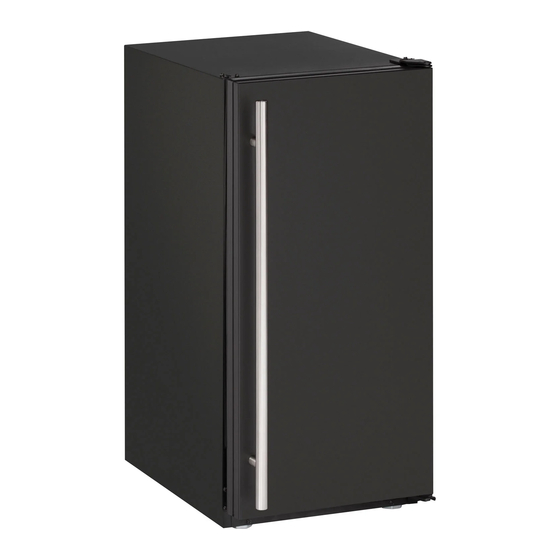
• U-ADA15IMB-00
• U-ADA15IMS-00
• U-ADA15IMS-01
• U-BI2115B-00
• U-BI2115B-20
• U-BI2115S-00
• U-BI2115S-01
• U-BI2115S-20
• U-BI3226S-22
• U-BI2115SOD-00
The American Built-In Undercounter Leader Since 1962
BI2115
BI95
• U-BI2115SOD-01
• U-BI2115SOD-20
• U-BI2115SOD-22
• U-BI2115W-00
• U-BI2115W-20
• ULN-BI95B-00
• ULN-BI95B-20
• ULN-BI95BTP-03
• ULN-BI95BTP-20
• ULN-BI95WH-00
SS98
SP18
• ULN-BI95WH-20
• ULN-BI98B-00
• ULN-BI98B-20
• ULN-BI98WH-00
• ULN-BI98WH-20
• ULN-SP18B-03
• ULN-SP18B-20
• ULN-SS1095FC-03
• ULN-SS1095FC-20
• ULN-SS1095FD-03
®
BI98
SS1095
• ULN-SS1095FD-20
• ULN-SS1095NF-03
• ULN-SS1095NF-20
• ULN-SS98-03
• ULN-SS98-20
• ULN-WH95TP-03
• ULN-WH95TP-20
ULINE.COM
Advertisement
Table of Contents

Related Manuals for U-Line U-ADA15IMB-00


Summary of Contents for U-Line U-ADA15IMB-00
- Page 1 INSTALL GUIDE ® ICEMAKER SERIES ADA15IM BI2115 SS98 BI98 WH95 BI95 SP18 SS1095 Models Covered • U-ADA15IMB-00 • U-BI2115SOD-01 • ULN-BI95WH-20 • ULN-SS1095FD-20 • U-ADA15IMS-00 • U-BI2115SOD-20 • ULN-BI98B-00 • ULN-SS1095NF-03 • U-ADA15IMS-01 • U-BI2115SOD-22 • ULN-BI98B-20 • ULN-SS1095NF-20 • U-BI2115B-00 •...
-
Page 2: Table Of Contents
1 Table of Contents Safety Precautions Safety Alert Definitions............................1 General Precautions ..............................1 Inspect & Plan Product Registration .............................2 Models Covered..............................2 Tools / Material Required ............................2 Exterior Cleaning ..............................2 Prepare Site Cut-Out Dimensions.............................3 ADA15IM Models ............................3 BI-95(B)(WH) Models..........................3 BI-98 / SS-98 Models ..........................3 BI-2115 Models............................ -
Page 3: Safety Precautions
Consult the installation guide before any installation begins. U-Line contact information appears on the rear WARNING cover of this guide. SHOCK HAZARD - Electrical Grounding Required. -
Page 4: Inspect & Plan
ULN-WH95TP-03 basis. For best results use Claire Stainless Steel Polish and ULN-BI95WH-00 Cleaner, which can be purchased from U-Line Corporation (Part numbers 173348). Frequent cleaning will remove surface contamination that could lead to rust. Some installations may Please carefully follow the directions that apply to your unit and require cleaning on a weekly basis. -
Page 5: Prepare Site
4 Prepare Site Filler Panel (Not Provided by U-Line) – May Be Added Above or Below Unit Your U-Line product has been designed for either free-standing or to Enclose for a Built-In Look built-in installation. When built-in, your unit does not require additional air space for top, sides or rear. -
Page 6: Ss-1095Nf Models
SS-1095NF Models BCM95 Models Filler Panel (Not Provided by U-Line) – Filler Panel (Not Provided by U-Line) – May Be Added Above or Below Unit Needed to Attach Mounting Flange on Unit to Enclose for a Built-In Look Typical Counter 18-1/2””... -
Page 7: Product Dimensions
ADA15IM BI95 95TP BCM95 5 Product Dimensions ADA15IM Series BI95(B)(WH) BI2115 17” * 23”* 23-3/16" 25-1/16" 32” 34-1/8" 8-15/16” 13-15/16" 15” 3-13/16” *Add 1-1/2” For Water Line Clearance 15" BI95BTP *Add 5/8” For Water Line Clearance *Add 3/4” To Depth For Water Line Clearance BI2115 Stainless ADA15IM Stainless Series 17"*... -
Page 8: Ss1095 Sp18 Bcm95 Wh95 Ss1095Nf
SS1095 SP18 BCM95 WH95 SS1095NF SS1095FD SP18 15-1/8" 15-15/16” 17” * 26-1/16” 18-7/8" 7 9/16”" 9” 1/2" 24-1/2" * *Add 1 1/2” For Water Line Clearance SS1095FC *Add 1-1/2” For Water Line Clearance BCM95 15-1/8” 17” * 15-1/8" 17"* 25-1/8” 25-1/8"... -
Page 9: Door Swing Dimensions
Door Swing Dimensions 6 Other Site Requirements All units have a zero clearance for the door to open 90°. U-Line recommends a minimum door clearance of 2" to accommodate Power Supply the handle if the unit is installed next to a wall or similar type of structure. -
Page 10: Door Reversal
5. Relocate plastic spacer/ bushing on bottom of door to opposite side, and place door on bottom hinge pin. See Figure 5. Clean out bushing hole in door bottom with a screwdriver if necessary. U-Line Product Features... -
Page 11: Wh95Tp, Bi95Btp, Bcm95 & Sp18
13. Gently slide travel pin assembly through flange and then fasten to unit. Make sure travel pin in door engages the closer in the assembly, then tighten screws on travel pin assembly securely. U-Line Door Reversal... -
Page 12: Ss1095
6. Install hinge on opposite side, bottom of cabinet (Figure 23). Align hinge outer edge with cabinet before tightening screws. 12. Remove pivot screw from top hinge, invert screw and reinstall pivot screw in top hinge (Figure 27). U-Line Product Features... - Page 13 Fasten upper hinge to unit (three screws (Figure 30). Partially tighten screws. 16. Adjust door to assure proper seal. Tighten upper and lower hinge screws securely. 17. Replace screws in holes in bottom of unit on opposite side. 18. Replace the grille. U-Line Door Reversal...
-
Page 14: Door Panel Installation Door Panel Preparation
Remove door by tilting forward and lifting off bottom hinge pin. 2. Pull door gasket out of groove (top edge of door only). Start in the middle and pull outward, moving toward the edge. This may take some force. BI-95 BI-2115 BI95BTP U-Line Product Features... -
Page 15: Power Supply
2. Align door squarely with cabinet. Make sure gasket is firmly in 24" 21-1/2" contact with cabinet all the way around the door (no gaps). Minimum 7" 7" 3. Tighten bottom hinge screws. 4" 1" 4. Tighten top hinge screws. U-Line Other Requirements... -
Page 16: Plumbing
IMPORTANT IMPORTANT U-Line requires the use of copper tubing for installation. Do not use any plastic water supply line. The line is under pressure at all times. Plastic may crack or rupture with age and cause water damage to your home. -
Page 17: Install
Installation 12 Install 1. Open the water supply valve in the main water source. Leveling Information 2. Plug in the powercord. ADA15IM & BI2115 3. Gently push the unit into position. Be careful not to kink the It is recommended that the unit is level. water supply line or entangle the electrical cord. -
Page 18: Installation Troubleshooting
The custom overlay door was designed to align with the rest of the cabinet doors, but the unit has crept forward. Solution Make sure that the electrical cord and water supply line are not obstructing the installation. U-Line Product Features... -
Page 19: Product Information
E-mail: onlineparts@u-line.com BUILDING ON THREE GENERATIONS OF INNOVATION For nearly five decades and three generations, U-Line continues to be the leader in innovation, quality and value in the premium built-in undercounter ice making, refrigeration and wine preservation market. U-Line has captivated those with an appreciation for the finer things with exceptional functionality, style, inspired innovation and attention to even the smallest details.