
Subscribe to Our Youtube Channel
Related Manuals for U-Line BI95FCB


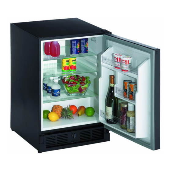
Summary of Contents for U-Line BI95FCB
- Page 1 Service Manual 2010 SP 18 ULN-95 Icemaker ULN-98 Icemaker ULN-SS1095 Icemaker U-CO29F U-CO29A ULN-29R U-1075BEV U-1075WC U-CO1175 BI-2115 ADA15IM Entertain with U-Line Elegance www.u-line.com...
- Page 2 POTENTIAL PROBLEMS WITH HFC-134A Three generations of pride and quality manufacturing and design improvements are built into all U-Line products. The This service manual has been written to cover products result: U-Line leads the market with innovative technology and manufactured with HFC-134A. HFC-134A compressors superior craftsmanship.
-
Page 3: Table Of Contents
Ice Maker Diagnosis Flow Chart..........................2-3 Troubleshooting ................................2-4 SECTION 3 - SERVICE AND REPAIR Refrigeration Systems..............................3-1 Normal Vapor/Compression Cycle Refrigeration..................3-1 U-Line Frost Free Refrigeration System .......................3-2 Compressor/Electrical Specifications........................3-4 Ice Maker Operating Cycles ............................3-6 Ice Maker Operating Cycles (Model U-CO29F)....................3-8 Temperature Control Specifications ........................3-9 Limit Switch Specifications ............................3-10... -
Page 4: Section 1 - General Information
Caution means that failure to follow this safety statement cooling unit. may result in minor or moderate personal injury, property • Use only genuine U-Line replacement parts. Imitation or equipment damage. parts can damage the unit, affect its operation or General Precautions performance and may void the warranty. -
Page 5: U-Line Corporation Limited Warranty
U-Line product to be free from defects in materials and workmanship for a period of five years from the date of purchase. During the initial one-year warranty period for all U-Line products U-Line shall: (1) at U-Lines option, repair any product or replace any part of a product that breaches this warranty;... -
Page 6: Product Liability Policy
Line’s evaluation, any claim for damage may be declined. If the unit in question is a U-Line CLR or CLRCO with a drain pump, both the unit and the drain pump (regardless of the manufacturer) must be returned to U-Line Corporation. -
Page 7: Serial Number Format
The next four digits of the first segment, 9469, represent the At U-Line, parts and labor claims are paid separately. Included shop order number. Order number 9469 is assigned for the in labor are freon and recovery charges, all other parts are Model CLR2160 B-00 units. -
Page 8: Parts Listing
REPLACEMENT PARTS: Use only genuine U-Line replacement All warranty parts will be shipped at no charge as long as parts. The use of non-U-Line parts can reduce ice rate, cause water warranty status has been confirmed. If we require that a part... - Page 9 Section 1 - General Information This page intentionally left blank.
-
Page 10: Section 2 - Troubleshooting
• Are you aware of the factory specifications for ice production? • Is the ice maker bin arm down? When the arm is up, the ice maker will not make ice. • Is the door or drawers sealing properly? U-Line’s warranty is 90 days for door adjustments. -
Page 11: Refrigeration System Diagnosis Guide
Section 2 - Troubleshooting REFRIGERATION SYSTEM DIAGNOSIS GUIDE System Suction Suction Compressor Condenser Capillary Evaporator Wattage Pressure Line Discharge Tube Condition Normal Normal Slightly below Very hot Very hot Warm Cold Normal room temperature Overcharge Higher than Very cold may Slightly warm Hot to warm Cool... -
Page 12: Ice Maker Diagnosis Flow Chart
Section 2 - Troubleshooting ICE MAKER DIAGNOSIS FLOW CHART DOES THE UNIT REFRIGERATE? Sealed System Leak Low Voltage Electrical Failure Voltage Drop Compressor Failure Wiring Fan Motor Failure Defrost System Failure DOES THE UNIT HARVEST ICE IF THE EJECTOR BLADES ARE MOVED BY HAND OR WITH A WRENCH ? Temperature Control Failure... -
Page 13: Troubleshooting
Section 2 - Troubleshooting TROUBLESHOOTING DANGER Never attempt to repair or perform maintenance on the unit until the main electrical power has been disconnected from the unit Additional specific troubleshooting information can be found in Theory of Operation - Section 3, under the applicable model. Cause Remedy Will not eject ice (water frozen). - Page 14 Section 2 - Troubleshooting Cause Remedy Low ice production. 1. Control set too cold. 1. Adjust control warmer (counterclockwise). 2. Fan motor stalled. 2. Replace fan motor. 3. Ice cubes too large. 3. Lower water fill adjustment. 4. Dirty condenser. 4.
- Page 15 Section 2 - Troubleshooting Cause Remedy Water leak (under unit). 1. Water supply line leaking at solenoid valve inlet. 1. Tighten fitting or replace fitting gasket and/or fitting. 2. Water line leaking at solenoid valve outlet. 2. Replace water line and fitting. 3.
-
Page 16: Section 3 - Service And Repair
Section 3 - Service and Repair REFRIGERATION SYSTEMS The pressure of the refrigerant is reduced to the evaporating, or low side, pressure. Normal Vapor/Compression Cycle • The reduction of pressure on the liquid refrigerant causes Refrigeration it to boil, or vaporize, until it reaches saturation temperature. - Page 17 Section 3 - Service and Repair DEFROST MODE Frost Free Refrigeration • Bypass solenoid valve open. COOLING MODE • Refrigerant flows through bypass system. • Bypass solenoid closed. • Vapor flows from condenser to evaporator without a • Evaporator fan operating. phase change.
- Page 18 Section 3 - Service and Repair Air flow in at evaporator blade Air passes though fin tube evaporator Air flow out at evaporator outlet Condensate drains down past the evaporator, into drain pan, and into condensate pan through drain hose. The drain trough is warmed during defrost by contact with evaporator fins.
-
Page 19: Compressor/Electrical Specifications
Section 3 - Service and Repair COMPRESSOR/ELECTRICAL Models ULN-95, ULN-98, SP18, U-CO29A, U-CO1175, BI2115, SS-1095 - Figure 4 SPECIFICATIONS EMI30HER Start winding resistance28 OHMS EMI30HER Run winding resistance8 OHMS Compressor Pins SD39 Start winding resistance11 OHMS To measure start winding resistance, measure across the C-S SD39 Run winding resistance5 OHMS pins. - Page 20 Section 3 - Service and Repair MODELS U-1075BEV, U-1075WC, 29R- Figure 6 EMI30HER Start winding resistance21.2 OHMS EMI30HER Run winding resistance7.9 OHMS OVERLOAD PROTECTOR STARTING RELAY RELAY COVER CAPACITOR UL183-3.1 Figure 6. Electrical Relay and Overload Protector Models U-1075BEV, U-1075WC, 29R...
-
Page 21: Ice Maker Operating Cycles
Section 3 - Service and Repair ICE MAKER OPERATING CYCLES Freeze Cycle ( • Power to the compressor. Figure 7 • Power to the condenser fan. • Temperature control terminals 2 and 3 are closed. black black black SWITCH ground MOTOR brown WATER... - Page 22 Section 3 - Service and Repair Harvest-2 Cycle ( Figure 9 • Ice maker ejector blades reach approximately 2:00 position and • Ejector blades stall on ice and ice maker motor pulsates until cam depresses the hold switch. Power goes through the hold mold heater warms and ice releases.
-
Page 23: Ice Maker Operating Cycles (Model U-Co29F)
Note: The refrigeration system operates independently of the ice • Ejector blades stall on ice and ice maker motor pulsates until maker. This is a new design for U-Line. All other U-Line ice makers mold heater warms and ice releases. -
Page 24: Temperature Control Specifications
Section 3 - Service and Repair TEMPERATURE CONTROL and senses mold temperature. After ice is sensed in the mold, the 2-3 contacts open (stopping the compressor) and the 2-1 SPECIFICATIONS contacts are closed (starting the ice maker motor). The 2-3 contacts close (2-1 contacts open) before the end of the ice Double Throw Ice Maker Thermostat harvest cycle.The hold switch prevents power going back to... -
Page 25: Limit Switch Specifications
Section 3 - Service and Repair LIMIT SWITCH SPECIFICATIONS The function of this switch is to open in the event of an overheating condition. This bi-metal thermostat is normally • Normally closed Bi-metal switch closed and does not initiate the ice harvest cycle. The ice •... -
Page 26: Replacing Ice Maker Assembly (Co29F Only)
Section 3 - Service and Repair REPLACING ICE MAKER ASSEMBLY 7. Remove three screws from wall of freezer housing (5). (CO29F ONLY) 8. Remove ice maker assembly. 9. Place new ice maker assembly into position and secure with three 1. Unplug the unit from the main power source. screws (5). - Page 27 Section 3 - Service and Repair THIS PAGE INTENTIONALLY LEFT BLANK 3-12...
- Page 28 Section 4 - Parts 220 VOLT CONVERSION LIST 110V P/N 220V P/N Description 5263-S 5195 Fan motor All models listed in this manual are equipped to run on 110/115 volt. This document is a conversion list for the 80-39015-00 628109 I.M motor (ice makers) applicable 220 volt parts for the following models: Ice maker assembly...
- Page 29 Section 4 - Parts U-LINE ICE MAKER ASSEMBLY...
- Page 30 U-LINE ICE MAKER ASSEMBLY U-Line no longer offers individual ice maker parts for replacement. If there is a defect in the ice maker assembly, you have the choice of replacing the face plate assembly or the complete ice maker assembly.
-
Page 31: Model Sp18
Section 4 - Parts MODEL SP18... - Page 32 Section 4 - Parts MODEL SP18 Item Part No. Black Part No. White Description SP18B-TRAVELPIN SLV-TRAVEL-PIN Travel Pin Assembly 31476-BLK 31476-SS Pin only Ice Maker Assembly Face Plate Assembly (See page 2) SP18B-FRAME SP18-FRAME Trim frame (includes rivets) 11698-SSB-S 11698-SS-S Hinge Assembly, top (includes screws) 41915 41915...
-
Page 33: Model Uln-95 - Bi95B, Bi95Wh, Bcm95
Section 4 - Parts MODEL ULN-95 (1 OF 2) BI95B, BI95WH, BCM95 26 22, 23... - Page 34 Section 4 - Parts MODEL ULN-95 (1 OF 2) BI95B, BI95WH, BCM95 Item Part No. Part No. Part No. Description BI95B BI95WH BCM95 2053 2053 2053 On/Off switch 31489-1-BLK 31489-1-KIT 31489-1-BLK Door handle 31493-1-GRY 31493-1-WHT 31493-1-GRY Gasket, door 11697-ST-BLK 11697-ST-KIT 11697-ST-BLK Hinge, top 11695-S-BLK...
-
Page 35: Model Uln-95 - Bi95Btp, Wh95Tp, Ss95
Section 4 - Parts MODEL ULN-95 (2 OF 2) BI95BTP, WH95TP, SS95 26 22, 23... - Page 36 Section 4 - Parts MODEL ULN-95 (2 OF 2) BI95BTP, WH95TP, SS95 Item Part No. Part No. Part No. Description BI95BTP WH95TP SS95 2053 2053 2053 On/Off switch 31489-1-BLK 11777 31489-1-BLKDoor handle 31493-1-GRY 31493-1-WHT 31493-1-GRY Gasket, door 11698-SSB-S 11698-SS-S 11698-SSB-S Hinge, top 11696-SSB-S 11696-S-KIT...
-
Page 37: Model Uln-98 - Bi98B, Bi98Wh, Ss98
Section 4 - Parts MODEL ULN-98 BI98B, BI98WH, SS98 22, 23 4-10... - Page 38 Section 4 - Parts MODEL ULN-98 BI98B, BI98WH, SS98 Item Part No. Part No. Part No. Description BI98B BI98WH SS98 2053 2053 2053 On/Off switch 31489-2-BLK 31489-2-KIT 31489-2-BLK Door handle 31493-2-GRY 31493-2-WHT 31493-2-GRY Gasket, door 11697-ST-BLK 11697-ST-KIT 11698-SSB-S Hinge, top 11695-S-BLK 11695-S-KIT 11696-SSB-S...
-
Page 39: Model Ss-1095
Section 4 - Parts MODEL SS-1095 26 22, 23 4-12... - Page 40 Section 4 - Parts MODEL SS-1095 Item Part No. Description 2053 On/Off switch 14206-S Door handle 31493-1-GRY Gasket, door 11698-SS-S Hinge, top 11696-SS-S Hinge, bottom 80-29017-02 Grille, flush with door 80-29017-01 Grille, flush with cabinet & no frame 2628-S Condenser Assembly Ice Maker Assembly Face Plate Assembly (See page 2) 31429...
-
Page 41: Model U-Co29F
Section 4 - Parts MODEL U-CO29F Model U-CO29F (1 of 2) 26, 27 28 29 4-14... - Page 42 Section 4 - Parts MODEL U-CO29F (1 OF 2) Item Part No. Black Part No. White Description 80-35003-S 80-35003-S Freezer Housing Assembly 26069-S 26069-S Freezer Door Assembly 12013-S 12013-S Hinges, freezer door 42135 42135 Spring, hinge, freezer door 42157 42157 Tape, hinge, freezer door 40010-09 40010-09...
- Page 43 Section 4 - Parts MODEL U-CO29F (2 OF 2) 26, 27 28 29 4-16...
- Page 44 Section 4 - Parts MODEL U-CO29F (2 OF 2) Item Part No. Black Part No. White Description 41125 41125 Foot, cabinet 2053 2053 On/Off switch 2552A 2552A Water valve 41826 41826 Fitting, brass, 90° 41254 41254 Plastic Nut & Sleeve Assembly 404FF 404FF Fill Tube Assembly...
-
Page 45: Model U-Co29A
Section 4 - Parts MODEL U-CO29A 4, 5 36 35 CO29A 4-18... - Page 46 Section 4 - Parts MODEL U-CO29A Item U-CO29B-03 U-CO29WH-03 U-CO29B-00 U-CO29WH-00 Description 11957-S 11957-S 11957-S 11957-S Flap Door Assembly 31463 31463 31463 31463 Clamp, flap door 31434-1 31434-1 31434-1 31434-1 Snap rivets 40010-09 40010-09 40010-09 40010-09 Glass shelves 31443-6 31443-6 31443-6 31443-6 Trim, shelf front...
-
Page 47: Model Uln-29R
Section 4 - Parts MODEL ULN-29R 3, 5 25 29 4-20... - Page 48 Section 4 - Parts MODEL 29R Item Part No. Black Part No. White Description 31391 31391 Drain trough 41885 41885 Screws 40010-08 40010-08 Glass shelf, no logo 25032-4 23052-4 Trim, rear, glass shelf 40010-07 40010-07 Glass shelf, with logo 11508 11508 Funnel drain cup 31578...
-
Page 49: Model U-1075Bev
Section 4 - Parts MODEL 1075BEV 4-22... - Page 50 Section 4 - Parts MODEL 1075BEV Item Part No. Description 80-17105-03 Door Assembly (Field Reversable ) 23050-01 Door handle 31493-4-BLK Gasket, door 23051-01 Nameplate 40010-16 Glass shelf 11988-03 Wood Front 20041 Screw 42106 Screw (used on wood only) 23026-03* Slide 18066-01 Wine Rack Assembly 25032-02...
-
Page 51: Model 1075Wc
Section 4 - Parts MODEL 1075WC 4-24... - Page 52 Section 4 - Parts MODEL 1075WC Item Part No. Description Item Part No. Description 80-17110-03 Door Assembly 41747-SSB Pivot screw, bottom Field Reversable 5400-S Compressor Assembly 23050-01 Door handle 11664 Grille Assembly 23051-01 Nameplate 14196 Bracket, light switch 31493-4-BLK Gasket, door 1916 Light switch Plunger 11988-03...
- Page 53 Section 4 - Parts U-CO1175 (PAGE 1 OF 2) 4-26...
- Page 54 Section 4 - Parts U-CO1175 (PAGE 1 OF 2) Item Part No. Black Part No. Description Stainless Steel 11957-S 11957-S Flap Door Assembly 31463 31463 Clamp, flap door 31434-1 31434-1 Snap rivet 40010-10 40010-10 Glass shelf 40010-11 40010-11 Glass shelf, wide 31443-8 31433-8 Trim, front, glass shelf...
- Page 55 Section 4 - Parts U-CO1175 (PAGE 2 OF 2) 4-28...
- Page 56 Section 4 - Parts U-CO1175 (PAGE 2OF 2) Item Part No. Black Part No. Description Stainless Steel 41319 41319 Leg, leveling 2053 2053 On/Off switch 2552A 2552A Water valve 41826 41826 Fitting, brass, 90° 41254 41254 Plastic Nut & Sleeve Assembly 404FF 404FF Fill Tube Assembly...
-
Page 57: Model Bi-2115
Section 4 - Parts MODEL BI-2115 4-30... - Page 58 Section 4 - Parts MODEL BI-2115 item Part No. Black Part No. White Part No. Description Stainless Steel 11964-01 11964-01 11964-01 Back panel 80-17073-01 80-17073-02 80-17073-03 Door Assembly, RH Hinge 80-17073-13 Door Assembly, LH Hinge 80-10050-01-S 80-10050-02-S 80-10050-03-S Evaporator/Cabinet Assembly 402-B12015 402-B12015 402-B12015...
- Page 59 Section 4 - Parts MODEL ADA15IM 4-32...
- Page 60 Section 4 - Parts MODEL ADA15IM Item Part No. Black Part No. Description Stainless Steel 11964-01 11964-01 Back Panel 402-BI2015 402-BI2015 Ice Maker Assembly Face Plate Assembly (see page 2-) 31430 31430 Ice Bucket 23029 23029 Nameplate 31447-BLK 31447-Blk Hole Plug 31604-GRY 31604-GRY Door Gasket...
- Page 61 Section 4 - Parts This page intentionally left blank 4-34...
-
Page 62: Section 5 - Wiring Diagrams
Section 5 - Wiring Diagrams ULN-95, ULN-98, SP18 & SS-1095 - 115 VOLT CO29F - 115 VOLT COMBO 29FF WIRING DIAGRAM POWER CORD ASSEMBLY ROCKER BLACK-HOT SWITCH ICEMAKER ASSEMBLY (SMOOTH) ICEMAKER CONTROL GREEN BLACK-NEUTRAL NO NC GROUND BLACK (RIBBED) YELLOW YELLOW FREEZER CONTROL... -
Page 63: U-Co29A, Co1175, Bi2115, Ada15Im - 115 Volt
Section 5 - Wiring Diagrams U-CO29A, CO1175A, BI2115, ADA15IM - 115 VOLT ULN-29R - 115 VOLT... -
Page 64: 1075Bev, 1075Wc - 115 Volt
Section 5 - Wiring Diagrams 1075BEV, 1075WC - 115 VOLT... -
Page 65: Uln-95, Uln-98, Sp18 & Ss-1095- 220 Volt
Section 5 - Wiring Diagrams ULN-95, ULN-98, SP18 & 22-1095 - 220 VOLT CO-29A, CO1175, BI2115, ADA15IM - 220 VOLT... - Page 66 E-mail: onlineparts@u-line.com ABOUT U-LINE Building on 45 years, U-Line has captivated those with an appreciation for the finer things with exceptional design, inspired innovations and attention to even the smallest details. U-Line is synonymous with premium built-in undercounter ice making, refrigeration and wine storage appli- ances, the U-Line Corporation is committed to luxury under the counter.
Need help?
Do you have a question about the BI95FCB and is the answer not in the manual?
Questions and answers