Table of Contents
Advertisement
Aircraft Flight Manual
TECNAM P92 EchoMKII
M
:
ANUFACTURER
COSTRUZIONI AERONAUTICHE
A
:P92 Echo MKII
IRCRAFT MODEL
: .............................
S
ERIAL NUMBER
: ...................................
B
UILD YEAR
R
EGISTRATION MARKINGS
This manual contains information to be furnished to the pilot as required by
LTF-UL in addition to further information supplied by the manufacturer.
This manual must always present on board the aircraft.
The aircraft is to be operated in compliance with information and limitations
contained herein.
Costruzioni Aeronautiche TECNAM S.p.A.
Via Maiorise
CAPUA (CE) – Italy
Tel. +39 (0) 823.62.01.34
WEB:
www.tecnam.com
This document and the information thereon is the property of Costruzioni Aeronautiche Tecnam S.p.A., and may only be used for the purpose for which
Tecnam products are supplied, and/or use and maintenance of Tecnam Aircraft.
Reproduction or use of the data, information, drawings thereon, in whole or in part, is strictly prohibited without the express written permission of
Costruzioni Aeronautiche Tecnam.
Doc. No. 92/265
Edition – Rev. 0
st
1
2020, February 26
TECNAM
: .................
th
S.p.A.
Advertisement
Chapters
Table of Contents

Related Manuals for Tecnam P92 Echo MKII


Summary of Contents for Tecnam P92 Echo MKII
- Page 1 WEB: www.tecnam.com This document and the information thereon is the property of Costruzioni Aeronautiche Tecnam S.p.A., and may only be used for the purpose for which Tecnam products are supplied, and/or use and maintenance of Tecnam Aircraft. Reproduction or use of the data, information, drawings thereon, in whole or in part, is strictly prohibited without the express written permission of...
- Page 2 Page 0 - 2 Section 0 NDEX Record of Revisions ............... 3 List Of effective Pages ............5 Foreword ................6 Section Lists ................7 Aircraft Flight Manual Edition - Rev. 0 INDEX...
- Page 3 These pages will be updated to the current regular revision date. In order to be constantly updated on change on this document from TECNAM, It is the responsibility of the owner to register on TECNAM website at: www.tecnam.com...
- Page 4 Page 0 - 4 Description of Revised page Revision First issue Aircraft Flight Manual Edition - Rev. 0 RECORD OF REVISIONS...
- Page 5 Page 0 - 5 2. L F EFFECTIVE AGES The List of Effective Pages (LOEP), applicable to manuals of every operator, lists all the basic AFM pages: each manual could contain either basic pages or one variant of these pages when the pages of some Supplements are embodied. Pages affected by the current revision are indicated by an asterisk (*) following the revi- sion code.
- Page 6 Before using the airplane, you are recommended to read carefully this manual: a deep knowledge of airplane features and limitations will allow you for operating the airplane safely. For further information, please contact: TECNAM S.p.A. COSTRUZIONI AERONAUTICHE Via MAIORISE CAPUA (CE) - ITALY ...
- Page 7 Page 0 - 7 4. S ECTION ISTS Section 1 General Section 2 Limitations Section 3 Emergency Procedures Section 4 Normal Procedures Section 5 Performances Section 6 Weight and Balance Section 7 Airframe and Systems Description Section 8 Ground Handling, Servicing and Maintenance Supplements Section 9...
- Page 8 Page 0 - 8 Intentionally left blank Aircraft Flight Manual Edition - Rev. 0 SECTION LISTS...
- Page 9 Page 1 - 1 Section 1 - GENERAL INDEX INDEX ....................1 Introduction .................. 2 Warning – Caution – Note ............2 Three View and Dimensions ............3 Three View ................3 Dimensions ................4 General Features ................5 Control Surfaces Travel Limits ..........5 Engine ..................
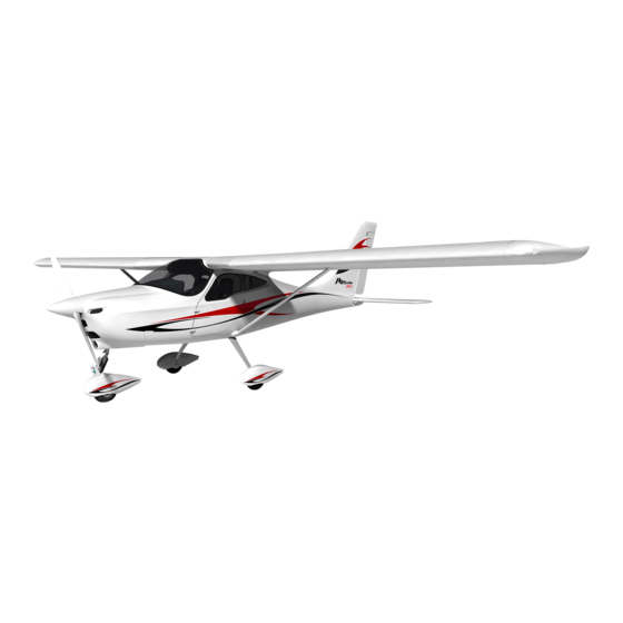
- Page 10 TECNAM P92 Echo MKII. The P92 Echo MkII is a twin seat, single engine light aircraft with a strut braced high wing and tricycle fixed landing gear with steerable nose wheel.
- Page 11 Page 3 - 1 HREE IEW AND IMENSIONS HREE Fig. 1.1 – General views Dimensions shown refer to normal operating tire pressure. Propeller ground clearance 336 mm Propeller ground clearance with deflated front tire and nose wheel shock ab- sorber compressed 84mm Section 1 - General Edition - Rev.
- Page 12 Page 1 -4 IMENSIONS Overall dimensions Wingspan 8.77 m /28.77 ft Length 6.81 m/22.34 ft Overall height 2.66 m/8.72 ft Wing Wing surface 12.1 m /130.24 ft Mean Geometric Chord 1.40 m/4.59 ft 1°30’ Dihedral Aspect ratio 6.35 Main Landing Gear Wheel Track 1.84 m/6.04 ft Wheelbase...
- Page 13 Page 1 -5 ENERAL EATURES ONTROL URFACES RAVEL IMITS The control surfaces travel limits are reported in the Aircraft Maintenance Manual. NGINE Manufacturer Bombardier Rotax GmbH Model 912 ULS2 Engine type 4 cylinder horizontally-opposed twins with overall displacement of 1352 c.c., mixed cooling, (water-cooled heads and air-cooled cylinders), twin carburetors, integrated reduction gear with torque...
- Page 14 Page 1 -6 Approved fuel: MOGAS ASTM D4814 MOGAS EN 228 Super/Super Plus (Min RON 95) AVGAS 100LL (ASTM D910) (see also Section 2) Two wing tanks integrated within the wing’s Fuel tanks leading edge. Equipped with finger strainers outlet and with drain fittings. Capacity of each wing tank 45 litres Tanks overall capacity...
- Page 15 Page 1 -7 WEIGHTS See Section 2. TANDARD WEIGHTS Empty Weight: see weighing record on Section 6. PECIFIC OADING MTOW 600 kg Wing Loading 49.6 kg/m Power Loading 6.1 kg/hp Section 1 - General Edition - Rev. 0 THE CONTROL SURFACES TRAVEL LIMITS ARE REPORTED IN THE AIRCRAFT MAINTENANCE MANUAL.
- Page 16 Page 1 -8 CRONYMS AND TERMINOLOGY ENERAL IRSPEED ERMINOLOGY YMBOLS Calibrated Airspeed is the indicated airspeed, corrected taking into account the errors related to the instrument itself and its installation. Indicated Airspeed is the speed shown on the airspeed indicator. True Airspeed is the CAS airspeed corrected taking into account altitude and temperature.
- Page 17 Page 1 -9 ETEOROLOGICAL TERMINOLOGY International Standard Atmosphere: is the air atmospheric standard condition at sea level, at 15°C (59°F) and at 1013.25hPa (29.92inHg). Official atmospheric pressure at airport level: it indicates the air- craft absolute altitude with respect to the official airport level. Theoretical atmospheric pressure at sea level: is the atmospheric pressure reported at the medium sea level, through the standard air pressure-altitude relationship, starting from the airport QFE.
- Page 18 Page 1 -10 IRCRAFT PERFORMANCE AND FLIGHT PLANNING TERMINOLOGY Crosswind Velocity is the velocity of the crosswind component for which adequate control of the airplane during take-off and landing is assured. Usable fuel is the fuel available for flight planning. Unusable fuel is the quantity of fuel that cannot be safely used in flight.
- Page 19 Maximum Landing Weight is the maximum weight approved for the land- ing touchdown (for P92 Echo MKII it is equivalent to the Maximum Takeoff Weight). Tare is the weight of chocks, blocks, stands, etc.
- Page 20 Page 1 - 12 NIT CONVERSION CHART MOLTIPLYING YIELDS EMPERATURE F 32 Fahrenheit [°F] [°C] Celsius 9 [°F] Celsius [°C] Fahrenheit C 32 5 ORCES Kilograms [kg] 2.205...
- Page 21 Page 1 - 13 / US ITRES GALLONS CONVERSION CHART Litres US Gallons US Gallons Litres 11.4 15.1 22.7 30.3 37.9 10.6 45.4 11.9 53.0 13.2 60.6 15.9 68.1 18.5 75.7 21.1 83.3 23.8 90.9 Section 1 - General Edition - Rev. 0 LITRES / US GALLONS CONVERSION CHART...
- Page 22 Page 1 - 14 INTENTIONALLY LEFT BLANK Section 1 - General Edition - Rev. 0...
- Page 23 Page 2- 1 Section 2 – LIMITATIONS INDEX INDEX ....................1 1. Introduction .................. 2 2. Speed limitations ................3 3. Airspeed indicator markings ............4 4. Powerplant limitations ..............5 5. Lubricant ..................6 6. Coolant Liquid ................6 7.
- Page 24 Page 2- 2 1. I NTRODUCTION Section 2 includes operating limitations and instrument markings of P92 Echo MKII aircraft, its engines and standard systems and equipment. Section 2 - Limitations Edition - Rev. 0 INTRODUCTION...
- Page 25 Page 2- 3 2. S PEED LIMITATIONS The following table addresses the airspeed limitations and their operational signif- icance: SPEED REMARKS [knots] [knots] V NE Never exceed speed Do not exceed this speed in any operation. V RA Do not exceed this speed Maximum speed for rough air except in smooth air, and only with caution.
- Page 26 Page 2- 4 3. A IRSPEED INDICATOR MARKINGS Airspeed indicator markings and their colour code are explained in the following table. MARKING EXPLANATION [knots] 41 – 70 White arc Positive Flap Operating Range (lower limit is 1.1V , at specified maximum weight and upper limit is the maximum speed permissi- ble with landing flaps extension).
- Page 27 Page 2- 5 4. P OWERPLANT LIMITATIONS Following table reports the operating limitations for aircraft engine installed: : Bombardier Rotax GmbH. NGINE MANUFACTURER : 912 ULS2 NGINE MODEL AXIMUM POWER Max Power Max RPM. Time max. kW (hp) Prop. RPM (engine) (minutes) 73.5 (98.5) 2388 (5800)
- Page 28 Page 2- 6 5. L UBRICANT Use viscosity grade oil as specified in the following table: 6. C OOLANT IQUID Coolant type and specifications are detailed into the “Rotax Operator’s Manual” and in its related documents. Section 2 - Limitations Edition - Rev.
- Page 29 Page 2- 7 7. P ROPELLER MANUFACTURER: Sensenich Propeller MODEL: W68T2ET-70J TYPE: Wood twin blade fixed pitch DIAMETER: 1730 mm (no reduction permitted) Section 2 - Limitations Edition - Rev. 0 PROPELLER...
- Page 30 Page 2- 8 8. M AXIMUM OPERATING ALTITUDE Maximum operating altitude is 14000 ft (4260 m) MSL. Flight crew is required to use supplemental oxygen according to Air Oper- ation Rules. CAUTION 9. A MBIENT EMPERATURE Ambient temperature: from -25°C to +50°C. Flight in expected and/or known icing conditions is forbidden.
- Page 31 Page 2- 9 10. P OWERPLANT INSTRUMENTS MARKINGS Powerplant instrument markings and their colour code significance are shown be- low: YELLOW RED RANGE GREEN RANGE RED RANGE RANGE Minimum Normal Maximum NSTRUMENT Caution limit operating limit Propeller ---- 580 - 2265 2265 - 2388 >2388 Engine...
- Page 32 Page 2- 10 12. W EIGHTS Condition Weight Maximum take-off weight 600 kg Maximum landing weight 600 kg Maximum zero wing fuel weight 600 kg Maximum baggage weight 20 kg 13. C ENTER OF GRAVITY RANGE Datum Propeller support flange without spacer Levelling Seat track supporting trusses (ref.
- Page 33 Page 2- 11 14. A PPROVED MANEUVERS The aircraft is intended for non-aerobatic operations only. Non aerobatic operations include: Any manoeuvre pertaining to “normal” flight Stalls (except whip stalls) Lazy eights Chandelles Turns in which the angle of bank is not more than 60° Aerobatic manoeuvres, including spins and turns with angle of bank of more than 60°, are not approved for such a category.
- Page 34 Page 2- 12 16. F LIGHT CREW Minimum crew for flight is one pilot seated on the left side. 17. M AXIMUM PASSENGER SEATING With the exception of the pilot, only one passenger is allowed on board of this aircraft. Section 2 - Limitations Edition - Rev.
- Page 35 Page 2- 13 18. F 45 liters each WO TANKS 90 liters. OTAL FUEL CAPACITY 86.9 liters SABLE FUEL Q 1.55 liters each (3.1 litres total) NUSABLE FUEL Q Compensate uneven fuel tank levels by acting on the fuel selector valve located into the cabin.
- Page 36 Page 2- 14 19. D EMONSTRATED ROSS PERATIONS The aircraft controllability during take-offs and landings has been demonstrated with a cross wind components up to 15 kts (28 km/h). 20. R ESCUE YSTEM EPLOYMENT Maximum airspeed for rescue system deployment is145kts IAS Section 2 - Limitations Edition - Rev.
- Page 37 Page 3 - 1 Section 3–EMERGENCY PROCEDURES INDEX INDEX ..................... 1 1. Introduction ................3 2. Airplane alerts ................4 Electric Power System 2.1. Malfunction..........4 Electrical fuel pump Failure ............ 5 2.2. Trim System 2.3. Failure5 Airplane evacuation ..............5 2.4.
- Page 38 Page 3 - 2 Power-On Forced 7.2. Landing............. Landing With A Flat Nose 7.3. Tire............. Landing With A Flat Main 7.4. Tire............8. Stall Recovery ................. 16 9. Recovery From Unintentional Spin ........17 10. Rescue System deployment ........... 18 11.
- Page 39 Page 3 - 3 1. I NTRODUCTION Section 3 includes checklists and detailed procedures to be used in the event of emergencies. Emergencies caused by a malfunction of the aircraft or engine are extremely rare if appropriate maintenance and pre-flight inspections are carried out.
- Page 40 Page 3 - 4 2. A IRPLANE ALERTS 2.1. LECTRIC OWER YSTEM ALFUNCTION Generator message alert Generator message alert (ALT) may appear on PFD for a faulty al- NOTE ternator or when voltage is above 16V, in this case the over-voltage sensor automatically shuts down the alternator Generator switch: Master switch:...
- Page 41 Page 3 - 5 2.2. LECTRICAL FUEL PUMP AILURE Electrical fuel pump switch: Electrical fuel pump switch: Fuel pressure: CHECK raise If fuel pressure doesn’t build up: Land as soon as possible monitoring fuel pressure. 2.3. YSTEM AILURE Locked Control Should trim control be inoperative, act as follows: Breakers: CHECK...
- Page 42 Page 3 - 6 NGINE SECURING Following procedure is applicable to shut-down the engine in flight: Throttle Lever IDLE Magnetos Fuel Selector Electrical fuel pump Generator switch Section 3 – Emergency Procedure Edition - Rev. 0 ENGINE SECURING...
- Page 43 Page 3 - 7 4. E NGINE AILURE NGINE AILURE URING Throttle: IDLE (fully out) Rudder Keep heading control Brakes: apply as needed When safely stopped: Magnetos: Fuel selector valve: Electric fuel pump: Generator & Master switches: 4.2. N INE AILURE MMEDIATELY FTER...
- Page 44 Page 3 - 8 4.3. NGINE AILURES URING LIGHT 4.3.1 Low Fuel Pressure If the fuel pressure indicator falls below the 2.2 psi (0.15 bar): Electric fuel pump: Fuel selector valve: change the fuel feeding tank Check both fuel quantity indicators If fuel pressure doesn’t build up: Land as soon as possible monitoring fuel pressure.
- Page 45 Page 3 - 9 4.3.3 High Oil Temperature If oil pressure is low see para. 4.3.2 Low Oil Pressure. If oil pressure is within limits: Throttle Lever REDUCE Minimum practical If oil temperature does not decrease Airspeed INCREASE If oil temperature does not come back within limits, the thermostatic valve (if embodied), regulating the oil flow NOTE to the heat exchangers, could be damaged or an oil...
- Page 46 Page 3 - 10 4.3.4 CHT/CT limit exceedance If CHT is above 135°C or CT is above 120 °C: Throttle Lever REDUCE Minimum practical Land as soon as practical If CHT/CT continues to rise and engine shows roughness or power loss: Land as soon as possible applying forced landing procedure (See Para.
- Page 47 Page 3 - 11 5. I LIGHT NGINE ESTART After a mechanical engine seizure, fire or a major propeller damage engine restart is not recommended. WARNING Electrical fuel pump Fuel quantity indicator CHECK Fuel Selector change the fuel feeding tank Magnetos BOTH Magnetos...
- Page 48 Page 3 - 12 6. S MOKE 6.1. NGINE FIRE ON THE GROUND Fuel Selector Electrical fuel pump Magnetos Throttle lever FULL POWER Cabin Heat Generator & Master Switches Parking Brake ENGAGED Aircraft Evacuation carry out immediately 6.2. NGINE URING BEFORE ROTATION: ABORT TAKE OFF Throttle Lever IDLE...
- Page 49 Page 3 - 13 6.3. NGINE LIGHT Cabin heating: Fuel selector valve: Electric fuel pump: Throttle: FULL FORWARD until the engine stops Magnetos: Cabin vents: OPEN Do not attempt engine restart WARNING Land as soon as possible applying forced landing procedure (See Para. 7). 6.4.
- Page 50 Page 3 - 14 7. L ANDING MERGENCY 7.1. ORCED ANDING ITHOUT NGINE OWER Flap: Airspeed (Best glide speed): 65 kts IAS Find a suitable place to land safely, plan to approach it upwind. Fuel selector valve: Electric fuel pump: Magnetos: Safety belts: Tighten...
- Page 51 Page 3 - 15 7.4. ANDING If it’s suspected a main tire defect or it’s reported to be defective: Pre-landing checklist: Complete Flaps: Land Land the aeroplane on the side of runway opposite to the defective tire (if detected) to compensate the change in direction which is to be expected during final rolling Touchdown with the GOOD TIRE FIRST (if detected) and hold aircraft with the flat tire off the ground as long as possible by mean of aileron...
- Page 52 Page 3 - 16 8. S TALL ECOVERY At the first indication of stall, for example, uncontrolled lateral departure, pitch down, stall warning: Pitch nose down: APPLY until impending stall indications are eliminated Wings level Obtain and Maintain Power: As required Return to the desired flight path Apply smooth and coordinated flight control movements to return the airplane to the desired flight path being careful to avoid a sec-...
- Page 53 Page 3 - 17 9. R ECOVERY NINTENTIONAL If unintentional spin occurs, the following recovery procedure should be used: Throttle: IDLE Rudder: full, in the opposite direction of the spin Stick: forward As the spin stops: Rudder: SET NEUTRAL smoothly recover averting speeds in Aeroplane attitude: excess of V and maximum load factor...
- Page 54 Page 3 - 18 10. R ESCUE YSTEM DEPLOYMENT Rescue system should be deployed in the event of a life-threating emergency where parachute activation is determined to be safer than continued flight and landing. Full deployment of parachute is achieved in about 4 seconds. Rescue system should only be activated when any other means of handling the emergency would not protect the occupants CAUTION...
- Page 55 Page 3 - 19 11. O THER MERGENCIES 11.1. NINTENTIONAL LIGHT CING ONDITIONS Carburettor ice is possible when flying at low engine rpm in visible moisture (outside visibility less than 5 km, vicinity of fog, mist, clouds, rain, snow or hail) and OAT less than 10°C. WARNING Immediately fly away from icing conditions (changing altitude and direc- tion of flight, out of clouds, visible moisture, precipitations)
- Page 56 Page 3 - 20 INTENTIONALLY LEFT BLANK Section 3 – Emergency Procedure Edition - Rev. 0 OTHER EMERGENCIES...
- Page 57 Page 4 - 1 Section 4 – NORMAL PROCEDURES INDEX 1. Introduction ................2 2. Airspeeds for normal operations ..........2 3. Pre-Flight Inspections .............. 3 3.1. Cabin Inspection ..............3 3.2. Aircraft walk-around ............3 4. Checklists ................. 6 4.1.
- Page 58 Page 4 - 2 1. I NTRODUCTION Section 4 contains checklists and the procedures for the conduction of normal op- eration. 2. A IRSPEEDS FOR NORMAL OPERATIONS Following airspeeds are significant for normal operations at MTOW (600 kg). FLAPS [kts] Rotation Speed (in take-off, V 0°...
- Page 59 Page 4 - 3 3. P LIGHT NSPECTIONS Before each flight, it is necessary to carry out a complete aircraft check compris- ing an external inspection followed by a cockpit inspection as below detailed. 3.1. ABIN NSPECTION Weight and balance: calculate (ref. this AFM sect. 6) check within limits Safety belts: connected to hard points, check condition Magnetos: OFF, keys extracted Master switch: ON...
- Page 60 Page 4 - 4 FIG. 4-1 Left hand fuel filler cap: check visually for desired fuel level and secure. Left tank vent: check for obstructions. Remove protection cap and check pitot mounted on left strut is unobstructed, do not blow inside vents, place protection cap inside aircraft. Left side leading edge and wing skin: visual inspection D Left aileron: visual inspection Left flap and hinges: visual inspection...
- Page 61 Page 4 - 5 Nose wheel strut and tire: check inflation 11 psi (0.8 bar), tire condition and con- dition of rubber shock absorber discs. Propeller and spinner condition: check for nicks and security. T Open engine cowling and perform the following checklist: Check no foreign objects are present.
- Page 62 Page 4 - 6 4. C HECKLISTS 4.1. EFORE NGINE TARTING FTER FLIGHT NSPECTION Seat position and safety belts adjustment Flight controls: operate until their stop checking for movement smoothness, free of play and friction. Parking brake: engage and brake pedal press/brake lever pull Throttle friction: adjust Circuit Breakers: check all IN Master switch: ON, Check Voltage (at least 10.5 V)
- Page 63 Page 4 - 7 4.2. NGINE TARTING Master switch ON. Engine throttle: idle Choke: as needed Fuel selector valve: select the tank with less fuel Electric fuel pump: ON Propeller area: call for CLEAR and visually check Check to insure no person or object is present in the area close to the propeller.
- Page 64 Page 4 - 8 4.4. AXIING 1. Brakes: check 2. Steering: check Flight parameters: check operation 4.5. RIOR 1. Parking brake: ON, brake pedal press / brake lever pull 2. Engine parameters: Check within limits Oil pressure: 2-5 bar (above 3500 rpm); 0.8 bar (below 3500 rpm) 3.
- Page 65 Page 4 - 9 4.6. LIMB On uncontrolled fields, before line up, check runway wind direction and speed and check for traffic on final WARNING 1. Parking brake: OFF 2. Throttle lever: Full Forward 3. Engine parameters: check 4. Rotation speed V MTOW 600kg 45 kts IAS...
- Page 66 Page 4 - 10 4.7. RUISE Set power at or below maximum continuous: 5500 rpm Check engine parameters within limits 4.8. EFORE ANDING Electric fuel pump: ON Fuel valve: select the fullest tank Landing Light (if applicable): ON On downwind, leg abeam touch down point: Flaps: set T/O MTOW 600kg...
- Page 67 Page 4 - 11 4.10. FTER ANDING 1. Flaps: UP 2. Electric Fuel Pump: OFF 3. Landing light (if installed): OFF 4.11. NGINE Parking brake: engage Keep engine running at about 2900 rpm for about one minute in order toreduce latent heat.
- Page 68 Page 4 - 12 INTENTIONALLY LEFT BLANK Section 4 – Normal Procedures Edition - Rev. 0 CHECKLISTS...
- Page 69 Page 5 - 1 Section 5 - PERFORMANCES INDEX INDEX ....................1 1. Introduction .................. 2 2. Use of performances charts ............3 3. Airspeed indicator system calibration ........4 4. ICAO Standard Atmosphere ............5 5. Stall speed ..................6 6.
- Page 70 Page 5 - 2 1. I NTRODUCTION This section provides all necessary data for an accurate and comprehensive plan- ning of flight activity from take-off to landing. Data reported in graphs and/or in tables were determined using: aircraft and engine in good condition ...
- Page 71 Page 5 - 3 2. U SE OF PERFORMANCES CHARTS Performances data are presented in tabular or graphical form to illustrate the effect of different variables such as altitude, temperature and weight. Given information is sufficient to plan the mission with required precision and safety. Additional information is provided for each table or graph.
- Page 72 Page 5 - 4 3. A IRSPEED INDICATOR SYSTEM CALIBRATION Graph shows indicated airspeed V as a function of calibrated airspeed V . 5-1. I NDICATED ALIBRATED IRSPEED Example: Given Find KCAS 75(FLAP UP) KIAS 76 (FLAP UP) NOTE Indicated airspeed assumes 0 as an instrument error Section 5 - Performance Edition - Rev.
- Page 73 Page 5 - 5 4. ICAO S TANDARD TMOSPHERE . 5-2. ICAO C HART Examples: Scope Given Find A: Pressure altitude = 1600ft → C: Density Altitude = 2550ft Density Altitude: B: Temperature = 20°C → E: ISA Air Temperature = 12°C ISA Temperature: D: Pressure altitude = 1600ft Section 5 - Performance...
- Page 74 Page 5 - 6 5. S TALL SPEED Weight: 600 kg Throttle Levers: IDLE CG: Most Forward (23%) No ground effect TALL PEED NGLE 0° LAPS LAPS LAPS [deg] KIAS KCAS KIAS KCAS KIAS KCAS NOTE Altitude loss during conventional stall recovery, as demonstrated during flight tests is approximately 200 ft with banking below 20°.
- Page 75 Page 5 - 7 6. C ROSSWIND Maximum demonstrated crosswind is 15 Kts Example: Given Find Wind direction ( ) = 30° Headwind = 17.5 Kts with respect to aircraft longitudinal axis Wind speed = 20 Kts Crosswind = 10 Kts .
- Page 76 Page 5 - 8 7. T OFF PERFORMANCE Weight = 600 kg Corrections Headwind: - 2.5m for each kt (8 ft/kt) Flaps: T/O Tailwind: + 10m for each kt (33ft/kt) Speed at Lift-Off = 45 KIAS Speed Over 50ft Obstacle = 50 KIAS Paved Runway: - 6% to Ground Roll Throttle Lever: Full Forward Runway slope: + 5% to Ground Roll for each +1%...
- Page 77 Page 5 - 9 Weight = 550 kg Corrections Headwind: - 2.5m for each kt (8 ft/kt) Flaps: T/O Tailwind: + 10m for each kt (33ft/kt) Speed at Lift-Off = 42 KIAS Speed Over 50ft Obstacle = 47 KIAS Paved Runway: - 6% to Ground Roll Throttle Lever: Full Forward Runway slope: + 5% to Ground Roll for each +1% Runway: Grass...
- Page 78 Page 5 - 10 Weight = 500 kg Corrections Headwind: - 2.5m for each kt (8 ft/kt) Flaps: T/O Tailwind: + 10m for each kt (33ft/kt) Speed at Lift-Off = 40 KIAS Speed Over 50ft Obstacle = 44 KIAS Paved Runway: - 6% to Ground Roll Throttle Lever: Full Forward Runway slope: + 5% to Ground Roll for each +1% Runway: Grass...
- Page 79 Page 5 - 11 8. R ATE OF LIMB Throttle lever: Full forward Flaps: Up = 65 KIAS = 62 KIAS Rate of Climb [ft/min] at Vy Pressure Weight Altitude Temperature [°C] [kg] [ft] S.L. 1318 1085 2000 1140 4000 6000 8000 10000...
- Page 80 Page 5 - 12 9. C RUISE PERFORMANCE Maximum takeoff weight = 600 kg (1320 lbs) (2) Fuel tanks 2x45 liters (11.9 gal) (less the unusable fuel) 0 ft OAT: +15°C Pressure altitude H Engine Speed Consumption KTAS (lt/h) 4300 4800 5200 Pressure altitude H...
- Page 81 Page 5 - 13 10. L ANDING PERFORMANCE Weight = 600 kg Corrections Headwind: - 5m for each kt (16 ft/kt) Flaps: LAND Tailwind: + 11m for each kt (36ft/kt) Final Approach Speed = 50 KIAS Throttle Levers: Idle Paved Runway: - 2% to Ground Roll Runway: Grass Runway slope: - 2.5% to Ground Roll for each +1% Pressure...
- Page 82 Page 5 - 14 Weight = 550 kg Corrections Headwind: - 5m for each kt (16 ft/kt) Flaps: LAND Tailwind: + 11m for each kt (36ft/kt) Short Final Approach Speed = 47 KIAS Throttle Levers: Idle Paved Runway: - 2% to Ground Roll Runway: Grass Runway slope: - 2.5% to Ground Roll for each +1% Pressure...
- Page 83 Page 5 - 15 Weight = 500 kg Corrections Headwind: - 5m for each kt (16 ft/kt) Flaps: LAND Tailwind: + 11m for each kt (36ft/kt) Short Final Approach Speed = 45 KIAS Throttle Levers: Idle Paved Runway: - 2% to Ground Roll Runway: Grass Runway slope: - 2.5% to Ground Roll for each +1% Pressure...
- Page 84 Page 5 - 16 INTENTIONALLY LEFT BLANK Section 5 - Performance Edition - Rev. 0 LANDING PERFORMANCE...
- Page 85 Page 6 - 1 SECTION 6 – WEIGHT and BALANCE INDEX Introduction ..................2 Weighing Procedure ................3 2.1 Preparation ................... 3 2.2 Levelling ..................3 2.3 Weighing ..................3 2.4 Determination of C.G. Location ............ 3 Weighing Report (I) ................5 Weighing Report (II) ................
- Page 86 Page 6 - 2 NTRODUCTION This section describes the procedure for establishing the basic empty weight and the moment of the aircraft. Loading procedure information is also provided. Aircraft must be operated in accordance with the limits con- NOTE cerning the maximum take-off weight and CG excursion as re- ported in Flight Manual Section 2.
- Page 87 Page 6 - 3 EIGHING ROCEDURE REPARATION Carry out weighing procedure inside closed hangar Remove from cabin any objects left unintentionally Insure on board presence of the Flight Manual Align nose wheel Drain fuel via the specific drain valve. ...
- Page 88 Page 6 - 4 Fig.6-1-P92 Echo MkII Edition, Rev 0 Section 6 – Weight and Balance WEIGHING PROCEDURES...
- Page 89 Page 6 - 5 EIGHING EPORT ModelP92Echo MKIIS/N: Weighing no. Date: Datum: Propeller support flange without spacer. meters Nose wheel weight Plumb bob distance LH wheel LH wheel weight Plumb bob distance RH wheel RH wheel weight Average distance (A Bob distance from nose wheel Empty weight We = W ...
- Page 90 Page 6 - 6 (II) EIGHING EPORT ModelP92Echo MKIIS/N: Weighing no. Date: Datum: Propeller support flange without spacer. meters Nose wheel weight Plumb bob distance LH wheel LH wheel weight Plumb bob distance RH wheel RH wheel weight Average distance (A Bob distance from nose wheel Empty weight We = W ...
- Page 91 Page 6 - 7 EIGHT AND ALANCE ETERMINATION FOR LIGHT In this subsection, the procedure to be used for the determination of aircraft weight and balance in flight is described. The weight and moment obtained must fall within the approved Weight-Moment Envelope (Figure 6-3). The procedure explained requires the use of: - Aircraft Weighing Report (I/II) - Weight and C.G.
- Page 92 Page 6 - 8 Table 6-1 -Weight and C.G.- Form Moment (M) = W * Arm [kg] [kg*m] Empty weight LOADING Pilot 1.948 Co-pilot 1.948 Baggage 2.320 Usable fuel Fuel (liters)*ρ (0.72) [kg] 1.774 fuel TAKE-OFF CONDITION Take-off condition ∑ W = ∑...
- Page 93 Page 6 - 9 Fig.6.2 L OADING DIAGRAM Edition, Rev 0 Section 6 – Weight and Balance WEIGHT AND BALANCE...
- Page 94 Page 6 - 10 Table 6-3 –Loading tables Pilot/Co-pilot loading [kg] [kg*m] 19.5 Baggage 29.2 loading 39.0 [kg] [kg*m] 58.4 77.9 97.4 13.9 116.9 18.6 126.6 23.2 136.4 27.8 146.1 32.5 155.8 37.1 165.6 41.8 175.3 46.4 185.1 194.8 Fuel loading [litres] [kg] [kg*m]...
- Page 95 Page 6 - 11 Fig.6.3 W EIGHT OMENT NVELOPE Edition, Rev 0 Section 6 – Weight and Balance WEIGHT AND BALANCE...
- Page 96 Page 6 - 13 Weight and balance 23% CMA 30% CMA (1841 mm) (1939 mm) 1750 1800 1850 1900 1950 2000 2050 CG POSITION - mm from datum Fig 6.4 C.G. RANGE CHART Edition, Rev 0 Section 6 – Weight and Balance EQUIPMENT LIST...
- Page 97 Page 6 - 13 QUIPMENT The following is a comprehensive list of all TECNAM supplied equipment for the P92 Echo MKII. The list consists of the following groups: Engine and accessories Landing gear Electrical system Instruments Avionics the following information describes each listing: ...
- Page 98 Page 6 - 14 EQUIPMENT LIST EIGHT ATUM & ESCRIPTION [kg] & NGINE ACCESSORIES ANDING GEAR AND ACCESSORIES ELECTRICAL SYSTEM C1.1 C1.2 C1.3 C2.1 Edition, Rev 0 Section 6 – Weight and Balance EQUIPMENT LIST...
- Page 99 Page 6 - 15 EQUIPMENT LIST EIGHT ATUM & ESCRIPTION [kg] NSTRUMENTS Edition, Rev 0 Section 6 – Weight and Balance EQUIPMENT LIST...
- Page 100 Page 6 - 16 EQUIPMENT LIST EIGHT ATUM & ESCRIPTION [kg] VIONICS AND THER Edition, Rev 0 Section 6 – Weight and Balance EQUIPMENT LIST...
-
Page 101: Table Of Contents
Page 7- 1 SEZIONE 7 – AIRFRAME AND SYSTEMS DESCRIPTION INDEX 1. Introduction ..................2 2. Airframe ................... 2 2.1. Wing ..................2 2.2. Fuselage ................. 2 2.3. Empennages ................3 3. F LIGHT ONTROLS ....................4. L ANDING EAR......................5. -
Page 102: Introduction
2.2. USELAGE The P92 Echo MkII fuselage is mainly made by carbon fibers composite materi- als. The fuselage is made by two main shells that are later assembled bonding the two main bodies and the floor (in composite material too) and adding aluminum stiffeners that allow the connection of the main landing gear, seats, wing and in- strument panel. -
Page 103: Empennages
Page 7- 3 LH outer shell Fig. 7-2.P92 Echo MkII fuselage 2.3. MPENNAGES The horizontal trimmable tail plane is all-moving type, which allows a high con- trol authority and a better stick free stability. The vertical tail is conventional fin and rudder type. -
Page 104: Flight Controls
Page 7- 4 STABILIZER Fig. 7-3. P92 Echo MkII stabilator and tab Fig. 7-4. P92 Echo MkII vertical tail and fin 3. F LIGHT ONTROLS The primary flight controls are of conventional type, operated by control stick and rudder pedals. Stabilator, as per Figure 7-4, is actuated by push-pull rods and ca- bles. - Page 105 Page 7- 5 Fig. 7-4. P92 Echo MkII stabilator control line system Ailerons, as per Figure 7-5, are actuated by push-pull rods on wing and cable in fuselage. Fig. 7-5. P92 Echo MkII aileron control line Edition, Rev 0 Section 7 – Airframe and Systems description...
- Page 106 Trim position indicator is installed on A/C cock- pit. In the following figure, the pitch trim tab actuation is shown. Actuator Trim tab connection Fig. 7-7. P92 Echo MkII trim tab control line Edition, Rev 0 Section 7 – Airframe and Systems description Flight Controls...
- Page 107 To flap hinge connection Actuator Fig. 7-8. P92 Echo MkII flap control system Edition, Rev 0 Section 7 – Airframe and Systems description Flight Controls...
-
Page 108: Landing Gear
The main landing gear is realized with simple steel spring-leaves, 5.00x5 wheel and tires, disc brakes, renowed for their operational record of effectiveness and safety. Fig. 7-9. P92 Echo MkII Main Landing Gear The nose gear features a steerable wheel with a rubber doughnut shock absorber. -
Page 109: Wheel And Breakes
VIONIC YSTEM The electric system installed on P92 Echo MkII is characterized by a rated voltage of 13.5 V DC furnished by a generator of 250 W DC. A 12-volts battery with a capacity of 18 Amph furnishes the power needed for aircraft start up and a reserve energy in case of Edition, Rev 0 Section 7 –... - Page 110 Circuit protec- tion is through breaker located on right side of instrument panel. The avionic system installed on P92 Echo MkII is based on Garmin G3X touch integrated avionic suite in a dual screen configuration (GDU 460). It provides flight information...
- Page 111 Page 7- 11 Fig. 7-13. P92 Echo MkII instrument panel Edition, Rev 0 Section 7 – Airframe and Systems description Avionic System...
-
Page 112: Powerplant
OWERPLANT 7.1. NGINE P92 Echo MkII is equipped with a Rotax 912 ULS 2 100 horse powered engine. Fig. 7-14. Rotax 912 ULS 2 engine The main engine characteristics are: 4 stroke, 4 cylinders. horizontally opposed, spark ignition engine, single central cam- shaft hydraulic tappets - push rods –... -
Page 113: Fuel System
Page 7- 13 YSTEM A sketch of the fuel system is given in Figure 7-15. It consists of two fuel tanks integrated in the wing leading edge and having a 45t (11.8 US gal) capacity (total capacity is 90lt (23.7 US gal)). -
Page 114: Luggage Compartment
Page 7- 14 UGGAGE OMPARTMENT The Luggage compartment is located behind the pilots' seats. Luggage shall be uni- formly distributed on utility shelf and its weight shall not exceed 20kg. Before loading luggage, check aircraft's weight and CG location (see Sect. 6) WARNING Edition, Rev 0 Section 7 –... -
Page 115: Doors
Page 7- 15 OORS Two doors are provided for P92 Echo MkII, on pilot and co-pilot side. Given that the pro- peller is located on the nose of the aircraft, there are no chances to endanger person using those exits. -
Page 116: Seats
Page 7- 16 EATS Pilot and co-pilot seats are characterized by aluminium structure (Al 6061) manufactured by Tecnam. It is covered by a cushion and connected to the fuselage structure. Fig. 7-17. P92 Echo MkII Seat Structure Edition, Rev 0 Section 7 –... -
Page 117: Rescue System
ESCUE YSTEM The P92 Echo MkII high wing aeroplanes hang under the parachute by means of four bridles. The front fitting points are dedicated fixations points near the front at- tachments of the wing. The rear two fitting points are located by the connection be- tween fuselage and the rear wing attachments. - Page 118 Page 7- 18 INTENTIONALLY LEFT BLANK Edition, Rev 0 Section 7 – Airframe and Systems description Rescue System...
- Page 119 Page 8- 1 SEZIONE 8 – AIRCRAFT CARE AND MAINTENANCE INDEX 1. Introduction ..................2 2. Aircraft Inspection Intervals ............3 3. Aircraft Changes or Repairs ............4 4. Ground Handling ................5 4.1. Towing ..................5 4.2. Parking and Tie-Down ............5 4.3.
-
Page 120: Introduction
Page 8- 2 1. Introduction This section contains factory-recommended procedures for proper ground handling and rou- tine care and servicing. It also identifies certain inspection and maintenance requirements, which must be followed if the aircraft is to retain its new-plane performance and dependabil- ity. -
Page 121: Aircraft Inspection Intervals
Page 8- 3 2. Aircraft Inspection Intervals Correct maintenance procedures are described in the aircraft’s Maintenance Manual or in the engine’s Maintenance Manual. Edition, Rev 0 Section 8 – Aircraft Care and Maintenance Aircraft Inspection Intervals... -
Page 122: Aircraft Changes Or Repairs
Page 8- 4 3. Aircraft Changes or Repairs Aircraft changes or repairs must be performed in accordance with Aircraft Maintenance Man- ual and only by TECNAM authorized personnel. Edition, Rev 0 Section 8 – Aircraft Care and Maintenance Aircraft Changes or Repairs... -
Page 123: Ground Handling
Page 8- 5 4. Ground Handling 4.1. OWING The aircraft is most easily and safely maneuvered by pulling it by its propeller near the axle. Aircraft may be steered by turning rudder or, for steep turns, by pushing lightly on tailcone to lift nose wheel. -
Page 124: Cleaning And Care
Page 8- 6 5. Cleaning And Care To clean painted surfaces, use a mild detergent such as shampoo normally used for car finish; use a soft cloth for drying. The plastic windshield and windows should never be dusted when dry; use lukewarm soapy water and dry using chamois only. It is possible to use special glass detergents but, in any case, never use products such as gasoline, alcohol, acetone or other sol- vents. - Page 125 Page 9 - 1 SECTION 9 – AFM SUPPLEMENTS INDEX Introduction ................ 2 Supplements List ..............3 Section 9 – AFM Supplements Edition - Rev. 0 INDEX...
- Page 126 NTRODUCTION This section concerns the supplemental manuals of additional (or optional) instru- mentation equipping the P92 Echo MKII and/or information and limitations re- lated to installed equipment configuration or needed to fit local national rules. Section 9 – AFM Supplements Edition - Rev.
- Page 127 Page 9 - 3 2. S UPPLEMENTS Aircraft S/N Registration marks Date APPLICABLE Sup. Title Rev. N Date Alternative Units for Speed Section 9 – AFM Supplements Edition - Rev. 0 SUPPLEMENTS LIST...
- Page 128 Page 9 - 4 INTENTIONALLY LEFT BLANK Section 9 – AFM Supplements Edition - Rev. 0...
- Page 129 Page S01 - 1 ° S01 UPPLEMENT N AFMS FOR Alternative Units for Speed ECORD OF EVISIONS Description of Revised page Revision First issue IST OF EFFECTIVE PAGES Section Pages Revision Rev 0 Section 0 Section 1 Rev 0 Rev 0 Section 2 Rev 0 Section 3...
- Page 130 Page S01 - 2 INTRODUCTION The information contained herein supplements or supersedes the basic Aircraft Flight Manual: detailed instructions are provided to allow the owner for replacing the AFM pages containing information amended per considering speeds in km/h. ’ T IS THE OWNER S RESPONSIBILITY TO REPLACE THE MENTIONED PAGES IN ACCORDANCE WITH THE INSTRUCTIONS HEREIN ADDRESSED SECTION BY SECTION...
- Page 131 Page S01 - 3 Supplement S01: pages replacement instructions SECTION 1 – GENERAL Refer to the basic AFM, Section 1 – General Section 9 – Supplements Edition - Rev. 0 Supplement N°S01 – Alternative Unit for Speed...
- Page 132 Page S01 - 4 Supplement S01: pages replacement instructions SECTION 2 – LIMITATIONS Make sure you first applied instructions reported on the basic AFM, Section 2 Limitations According A/C configuration apply following pages replacement: Supplement S01 LIMITATIONS Section 2 Page Page S2-3 REPLACES...
- Page 133 Alternative Unit for Speed Page S2 - 3 2. S PEED LIMITATIONS The following table addresses the airspeed limitations and their operational signif- icance: SPEED REMARKS [km/h] [km/h] V NE Do not exceed this speed in Never exceed speed any operation. V RA Maximum speed for rough air Do not exceed this speed...
- Page 134 Alternative Unit for Speed Page S2 - 4 3. A IRSPEED INDICATOR MARKINGS Airspeed indicator markings and their colour code are explained in the following table. MARKING EXPLANATION [km/h] 76 – 130 White arc Positive Flap Operating Range (lower limit is 1.1V , at specified maximum weight and upper limit is the maximum speed permissi-...
- Page 135 Alternative Unit for Speed Page S2 - 14 ESCUE YSTEM EPLOYMENT Maximum airspeed for rescue system deployment is 268 km/h IAS. Section 2 – Limitations Edition - Rev. 0 RESCUE SYSTEM DEPLOYMENT...
- Page 136 Page S01 - 5 Supplement S01: pages replacement instructions SECTION 3 – EMERGENCY PROCEDURES Make sure you first applied instructions reported on the basic AFM, Section 3 Emergency Procedures According A/C configuration apply following pages replacement: Supplement S01 EMERGENCY Section 3 PROCEDURES page Page...
- Page 137 Alternative Unit for Speed Page S3 - 7 NGINE AILURE 4.1. NGINE AILURE URING Throttle: IDLE (fully out) Rudder Keep heading control Brakes: apply as needed When safely stopped: Magnetos: Fuel selector valve: Electric fuel pump: Generator & Master switches: 4.2.
- Page 138 Alternative Unit for Speed Page S3 - 14 7. L ANDING MERGENCY ORCED ANDING ITHOUT NGINE OWER Flap: Airspeed: 120 km/h IAS Find a suitable place to land safely, plan to approach it upwind. Fuel selector valve: Electric fuel pump: Magnetos: Safety belts: Tighten...
- Page 139 Alternative Unit for Speed Page S3 - 18 10. R ESCUE YSTEM DEPLOYMENT Rescue system should be deployed in the event of a life-threating emergency where parachute activation is determined to be safer than continued flight and landing. Full deployment of parachute is achieved in about 4 seconds. Rescue system should only be activated when any other means of handling the emergency would not protect the occupants CAUTION...
- Page 140 Page S01 - 6 Supplement S01: pages replacement instructions SECTION 4 – NORMAL PROCEDURES Make sure you first applied instructions reported on the basic AFM, Section 4 Normal Procedures According A/C configuration apply following pages replacement: Supplement S01 NORMAL Section 3 PROCEDURES page Page...
- Page 141 Alternative Unit for Speed Page S4 - 2 1. I NTRODUCTION Section 4 contains checklists and the procedures for the conduction of normal op- eration. 2. A IRSPEEDS FOR NORMAL OPERATIONS Following airspeeds are significant for normal operations at MTOW (600 kg). FLAPS [km/h] Rotation Speed (in take-off, V...
- Page 142 Alternative Unit for Speed Page S4 - 9 4.6. T LIMB On uncontrolled fields, before line up, check runway wind direction and speed and check for traffic on final WARNING 1. Parking brake: OFF 2. Throttle: Full Forward 3. Engine parameters: check 4.
- Page 143 Alternative Unit for Speed Page S4 - 10 4.7. C RUISE Set power at or below maximum continuous: 5500 rpm Check engine parameters within limits 4.8. B EFORE ANDING Electric fuel pump: ON Fuel valve: select the fullest tank Landing Light (if applicable): ON On downwind, leg abeam touch down point: Flaps: set T/O MTOW...
- Page 144 Page S01 - 7 Supplement S01: pages replacement instructions SECTION 5 – PERFORMANCES Supplement S01 – Performances pages replace basic AFM Section 5 as whole Section 9 – Supplements Edition - Rev. 0 Supplement N°S01 – Alternative Unit for Speed...
- Page 145 Alternative Unit for Speed Page S5 - 1 Section 5 - PERFORMANCES INDEX 1. Introduction .................. 2 2. Use of performances charts ............3 3. Airspeed indicator system calibration ........4 4. ICAO Standard Atmosphere ............5 5. Stall speed ..................6 6.
- Page 146 Alternative Unit for Speed Page S5 - 2 1. I NTRODUCTION This section provides all necessary data for an accurate and comprehensive plan- ning of flight activity from take-off to landing. Data reported in graphs and/or in tables were determined using: ...
- Page 147 Alternative Unit for Speed Page S5 - 3 2. U SE OF PERFORMANCES CHARTS Performances data are presented in tabular or graphical form to illustrate the effect of different variables such as altitude, temperature and weight. Given information is sufficient to plan the mission with required precision and safety. Additional information is provided for each table or graph.
- Page 148 Alternative Unit for Speed Page S5 - 4 3. A IRSPEED INDICATOR SYSTEM CALIBRATION Graph shows indicated airspeed V as a function of calibrated airspeed V . 5-1. I NDICATED ALIBRATED IRSPEED Example: Given Find CAS 139 km/h IAS 141 km/h NOTE Indicated airspeed assumes 0 as an instrument error Section 5 –...
- Page 149 Alternative Unit for Speed Page S5 - 5 4. ICAO S TANDARD TMOSPHERE . 5-2. ICAO C HART Examples: Scope Given Find A: Pressure altitude = 1600ft → C: Density Altitude = 2550ft Density Altitude: B: Temperature = 20°C → E: ISA Air Temperature = 12°C ISA Temperature: D: Pressure altitude = 1600ft Section 5 –...
- Page 150 Alternative Unit for Speed Page S5 - 6 5. S TALL SPEED Weight: 600 kg Throttle Levers: IDLE CG: Most Forward (26%) No ground effect [km/h] TALL PEED NGLE 0° LAPS LAPS LAPS [deg] Altitude loss during conventional stall recovery, as demonstrated during flight tests is approximately 200 ft with banking below 20°.
- Page 151 Alternative Unit for Speed Page S5 - 7 6. C ROSSWIND Maximum demonstrated crosswind is 15 Kts (28 km/h) Example: Given Find Wind direction ( ) = 30° Headwind = 17.5 Kts with respect to aircraft longitudinal axis Wind speed = 20 Kts Crosswind = 10 Kts .
- Page 152 Alternative Unit for Speed Page S5 - 8 7. T OFF PERFORMANCE Weight = 600 kg Corrections Headwind: - 2.5m for each kt (8 ft/kt) Flaps: T/O Tailwind: + 10m for each kt (33ft/kt) Speed at Lift-Off = 83 km/h IAS Speed Over 50ft Obstacle = 93 km/h IAS Paved Runway: - 6% to Ground Roll Throttle Levers: Full Forward...
- Page 153 Alternative Unit for Speed Page S5 - 9 Weight = 550 kg Corrections Headwind: - 2.5m for each kt (8 ft/kt) Flaps: T/O Tailwind: + 10m for each kt (33ft/kt) Speed at Lift-Off = 78 km/h IAS Speed Over 50ft Obstacle = 87 km/h IAS Paved Runway: - 6% to Ground Roll Throttle Levers: Full Forward Runway slope: + 5% to Ground Roll for each +1%...
- Page 154 Alternative Unit for Speed Page S5 - 10 Weight = 500 kg Corrections Headwind: - 2.5m for each kt (8 ft/kt) Flaps: T/O Tailwind: + 10m for each kt (33ft/kt) Speed at Lift-Off = 74 km/h IAS Speed Over 50ft Obstacle = 81 km/h IAS Paved Runway: - 6% to Ground Roll Throttle Levers: Full Forward Runway slope: + 5% to Ground Roll for each +1%...
- Page 155 Alternative Unit for Speed Page S5 - 11 8. R ATE OF LIMB Throttle lever: Full forward Flaps: Up = 120 Km/h IAS = 115 Km/h IAS Rate of Climb [ft/min] at Vy Pressure Weight Altitude Temperature [°C] [kg] [ft] S.L.
- Page 156 Alternative Unit for Speed Page S5 - 12 9. C RUISE PERFORMANCE Maximum takeoff weight = 600 kg (1320 lbs) (2) Fuel tanks 2x45 liters (11.9 gal) (less the unusable fuel) Pressure altitude H 0 ft OAT: +15°C Engine Speed Consumption KTAS (lt/h)
- Page 157 Alternative Unit for Speed Page S5 - 13 10. L ANDING PERFORMANCE Weight = 600 kg Corrections Headwind: - 5m for each kt (16 ft/kt) Flaps: LAND Tailwind: + 11m for each kt (36ft/kt) Short Final Approach Speed = 93 km/h IAS Throttle Levers: Idle Paved Runway: - 2% to Ground Roll Runway: Grass...
- Page 158 Alternative Unit for Speed Page S5 - 14 Weight = 550 kg Corrections Headwind: - 5m for each kt (16 ft/kt) Flaps: LAND Tailwind: + 11m for each kt (36ft/kt) Short Final Approach Speed = 87 km/h IAS Throttle Levers: Idle Paved Runway: - 2% to Ground Roll Runway: Grass Runway slope: - 2.5% to Ground Roll for each +1%...
- Page 159 Alternative Unit for Speed Page S5 - 15 Weight = 500 kg Corrections Headwind: - 5m for each kt (16 ft/kt) Flaps: LAND Tailwind: + 11m for each kt (36ft/kt) Short Final Approach Speed = 83 km/h IAS Throttle Levers: Idle Paved Runway: - 2% to Ground Roll Runway: Grass Runway slope: - 2.5% to Ground Roll for each +1%...
- Page 160 Page S01 - 8 Supplement S01: pages replacement instructions SECTION 6 – WEIGHT and BALANCE Refer to the basic AFM, Section 6 – WEIGHT and BALANCE Section 9 – Supplements Edition - Rev. 0 Supplement N°S01 – Alternative Unit for Speed...
- Page 161 Page S01 - 9 Supplement S01: pages replacement instructions SECTION 7 – AIRFRAME AND SYSTEMS DESCRIPTION Refer to the basic AFM, Section 7 – AIRFRAME AND SYSTEMS DESCRIPTION Section 9 – Supplements Edition - Rev. 0 Supplement N°S01 – Alternative Unit for Speed...
- Page 162 Page S01 - 10 Supplement S01: pages replacement instructions SECTION 8 – GROUND HANDLING & SERVICE Refer to the basic AFM, Section 8 – GROUND HANDLING & SERVICE Section 9 – Supplements Edition - Rev. 0 Supplement N°S01 – Alternative Unit for Speed...
Need help?
Do you have a question about the P92 Echo MKII and is the answer not in the manual?
Questions and answers