Table of Contents
Advertisement
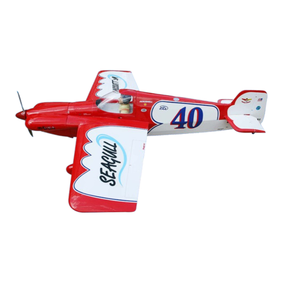
MS: 164
ASSEMBLY MANUAL
"Graphics and specifications may change without notice".
Specifications:
Wing span -----------------------------65in (165cm).
Wing area ---------------1038.5sq.in (67.0sq dm).
Weight ----------------------12.1-13.9lbs (5.5-6.3kg).
Length -----------------------------70.8in (179.8cm).
Engine -------------1.2-1.8cu.in -----2-4-stroke.
Engine --------------------------------20cc-26cc
Radio ---------- 4channels with 6 digital servos.
Advertisement
Table of Contents

Related Manuals for Seagull cassutt 3M Racer


Summary of Contents for Seagull cassutt 3M Racer
- Page 1 MS: 164 ASSEMBLY MANUAL “Graphics and specifications may change without notice”. Specifications: Wing span -----------------------------65in (165cm). Wing area ---------------1038.5sq.in (67.0sq dm). Weight ----------------------12.1-13.9lbs (5.5-6.3kg). Length -----------------------------70.8in (179.8cm). Engine -------------1.2-1.8cu.in -----2-4-stroke. Engine --------------------------------20cc-26cc Radio ---------- 4channels with 6 digital servos.
-
Page 2: Kit Contents
CASSUTT 3M RACER. INTRODUCTION. Thank you for choosing the CASSSUTT 3M RACER ARTF by SEAGULL MODELS COMPANY LTD. The CASSSUTT 3M RACER was designed with the intermediate/advanced sport scale in mind. It is a semi scale airplane which is easy to fly and quick to assemble. The airframe is conventionally built using balsa, plywood to make it stronger than the average ARTF , yet the design allows the aeroplane to be kept light. - Page 3 www.seagullmodels.com KIT CONTENTS. INSTALL AILERON CONTROL HORN. Fuselage Required Parts Wing set • Wing assembly (left and right) Tail set • Fiberglass control horn(2) Cowling Required Tools and Adhesives Canopy • 30-minute Epoxy Wing Tube Main landing gear 1) Locate the items for this section of the Tailwheel manual.
-
Page 4: Engine Mount Installation
Instruction Manual CASSUTT 3M RACER. INSTALL RUDDER CONTROL HORN. Required Parts • Tail set(Rudder) • Fiberglass Control horn(2) Required Tools and Adhesives • Fiberglass control horn 30-minute Epoxy 1) Locate the items for this section of the 2)Position the two Control horn on the Tail manual. -
Page 5: Installing The Stopper Assembly
www.seagullmodels.com Thread locker glue. INSTALLING THE STOPPER ASSEMBLY. Required Parts • Fuselage assembly • Fuel tank • Fuel tubing,550mm(not included) • Stopper assembly • Balsa wood include • Clunk Required Tools and Adhesives • 30-minute Epoxy Vent tube. Fuel pick up tube. 1) Using a modeling knife, carefully cut off the rear portion of one of the 3 nylon tubes leaving 1/2”... -
Page 6: Fuel Tank Installation
Instruction Manual CASSUTT 3M RACER. 4) Test fit the stopper assembly into the C/A glue. tank. It may be necessary to remove some of the flashing around the tank opening using a Fuel tank. modeling knife. If flashing is present, make sure none falls into the tank. - Page 7 www.seagullmodels.com INSTALLING THE FUSELAGE SERVO. Required Parts • Fuselage assembly Required Tools and Adhesives Elevator servo arm. • Drill • Drill bits:2mm • Phillips screwdrive (small) Because the size of servos differ, you may need to adjust the size of the precut open- ing in the mount.
-
Page 8: Mounting The Engine
Instruction Manual CASSUTT 3M RACER. MOUNTING THE ENGINE. Required Parts • Fuselage assembly • M4 Washer(8) Elevator servo arm. • Blind nut(4) • M4x30mm machine screw(4) • Engine • 1.2mmx600mm rod with nylon housing • Pushrod connector with setscrew and M2... - Page 9 www.seagullmodels.com 4mm diameter. 8) Reinstall the servo horn by sliding the 4) On the fire wall has the location for the connector over the pushrod wire. Center the throttle pusshrod tube (pre-drill). throttle stick and trim and install the servo horn perpendicular to the servo center line.
- Page 10 Instruction Manual CASSUTT 3M RACER. 4) Slide the collar to the axle and setscrew WHEEL AND WHEEL PANTS the collars to secure the collar to the axle and INSTALLATION. then slider the wheel on the axle with a drop of...
- Page 11 www.seagullmodels.com Landing Gear. wheel Pant. C/A glue. 7) Tighten the setcrews using a hex C/A glue. wrench to secure the collars on the axle over the flat spot to retain the wheel as shown. Repeat steps as above to attach Locker glue.
-
Page 12: Cowling Installation
Instruction Manual CASSUTT 3M RACER. 10) Place the fuselage inverted on the 1) Slide the fiberglass cowl over the workbench in a suitable stand. Set the landing engine and line up the back edge of the cowl gear in place and use a screwdrive to secure... - Page 13 www.seagullmodels.com The propeller should not touch any part of the spinner cone. If it does, use a sharp modeling knife and carefully trim away the spinner cone where the propeller comes in contact with it. Needle valve. 3) Install the muffler and muffler extension onto the engine and make the cutout in the cowl for muffler clearance.
- Page 14 Instruction Manual CASSUTT 3M RACER. 3) Use drill bit in a pin vise to drill the mouting 7) Apply 1-2 drops of thin C/A to each of the holes in the blocks. mounting tabs. Allow the C/A to cure without using accelerator.
- Page 15 www.seagullmodels.com AILERON PUSHROD HORN INSTALLATION Required Parts • Wing assembly(left and right) • 2.6mmx50mm threaded rod(2) • 3mm metal clevis with silicone tubing(4) • Lock nut(4) Required Tools and Adhesives • Phillips screwdrive • 30-mminute epoxy 50mm. M3 clevis. M3 lock nut. 70mm.
-
Page 16: Installing The Horizontal Stabilizer
Instruction Manual CASSUTT 3M RACER. Wing Aileron Wing Aileron Repeat the procedure for the other aileron servo. 3) Slide the stabilizer into place in the pre- INSTALLING THE HORIZONTAL cut slot in the rear of the fuselage. The stabi- STABILIZER. - Page 17 www.seagullmodels.com INSTALLING VERITICAL FIN. Required Parts • Fuselage assembly • Tail Set(Rudder and Elevator) Remove covering. Required Tools and Adhesives • Ruler,Pen,Knife • 30-mminute epoxy Fill epoxy. When cutting through the covering to re- move it, cut with only enough pressure to only cut through the covering itself.
- Page 18 Instruction Manual CASSUTT 3M RACER. 3) Slide the vertical stabilizer back in Required Parts place. Using a triangle, check to ensure that • 1000mm Cable(2) the vertical stabilizer is aligned 90º to the hori- • 2.6mmx80mm threaded rod(2) zontal stabilizer.
- Page 19 www.seagullmodels.com MOUNTING THE TALI WHEEL. Required Parts • Fuselage assembly • Tail wheel assembly • M3 Washer(2) • M3x30mm socket head screw(2) • M3x25mm machine screw(2) Required Tools and Adhesives • Phillips screwdrive • 30-minute epoxy 4) Thread one clevis and M3 lock nut on to •...
- Page 20 30-minute epoxy • Ruler 1) A scale pilot is included with this ARF. The Seagull Pilot included fitting well to the cockpit. (or you can order others scale pilot figures made by Seagull factory. They are available at Seagull distributors.)
-
Page 21: Apply The Decals
www.seagullmodels.com ATTACHMENT WING-FUSELAGE. Required Parts • Fuselage assembly • Wing assembly • Wing tube • M4x12mm socket head screw(2) • M4 washer(2) Required Tools and Adhesives 2x6mm • Phillips screwdrive • 30-minute epoxy • Drill bit 3mm • Drill APPLY THE DECALS. Locate the items neccesscery to install the wing set to fuselage . -
Page 22: Control Throws
Instruction Manual CASSUTT 3M RACER. With the wing attached to the fuselage, all parts of the model installed ( ready to fly), and empty fuel tanks, hold the model at the marked balance point with the stabilizer level. Lift the model. If the tail drops when you lift, the model is “tail heavy”... -
Page 23: Flight Preparation
www.seagullmodels.com PREFLIGHT CHECK. FLIGHT PREPARATION. 1) Completely charge your transmitter A) Check the operation and direction of and receiver batteries before your first day of the elevator, rudder, ailerons and throttle. flying. Plug in your radio system per the 2) Check every bolt and every glue joint manufacturer's instructions and turn every- in the CASSUT 3M RAVER to ensure that thing on.
Need help?
Do you have a question about the cassutt 3M Racer and is the answer not in the manual?
Questions and answers