Table of Contents
Advertisement
Quick Links
Download this manual
See also:
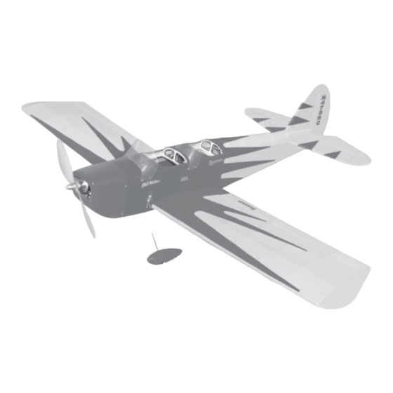
Assembly Manual
Specifications
Wing Span ------------------------------- 50 in --------------------- 127cm.
Wing Area ------------------------------- 217 sq in ------------ 14 sq dm.
Weight ------------------------------------ 30-42 oz --------- 850-1200 g.
Length ------------------------------------ 39 in ----------------------- 99cm.
Radio ------------------------------ 4 channel with 4 sub-micro servos.
Motor size ----------------------------- Himark Outrunner C3522-990.
Need to Complete
Speed Control: SJ Conquest 35 or 45 amp.
Recommended Battery 3-cell 11.1V 2200mAh to 3200mAh Li-Po.
Kit features.
•
Ready-made—minimal assembly & finishing required.
•
Ready-covered covering.
•
Photo-illustrated step-by-step Assembly Manual.
Made in Vietnam.
ASSEMBLY MANUAL
MS: X6
Advertisement
Table of Contents

Related Manuals for Seagull Space Walker II


Summary of Contents for Seagull Space Walker II
-
Page 1: Specifications
ASSEMBLY MANUAL MS: X6 Specifications Wing Span ------------------------------- 50 in --------------------- 127cm. Wing Area ------------------------------- 217 sq in ------------ 14 sq dm. Weight ------------------------------------ 30-42 oz --------- 850-1200 g. Length ------------------------------------ 39 in ----------------------- 99cm. Radio ------------------------------ 4 channel with 4 sub-micro servos. Motor size ----------------------------- Himark Outrunner C3522-990. - Page 2 ARTF , yet the design allows the aeroplane to be kept light. You will find that most of the work has been done for you already.Flying the SPACE WALKER II is simply a joy.
- Page 3 2mm ball driver. gluing! This will ensure proper as- Phillips head screwdriver. sembly as the SPACE WALKER II is 220 grit sandpaper. made from natural materials and 90° square or builder’s triangle. minor adjustments may have to be Wire cutters.
-
Page 4: Hinging The Ailerons
SPACE WALKER II. Instruction Manual. HINGING THE AILERONS. Note: The control surfaces, including the ailerons, elevators, and rudder, are prehinged with hinges installed, but the hinges are not glued in place. It is imperative that you properly adhere the hinges in place per the steps that follow C/A glue. -
Page 5: Hinging The Rudder
www.seagullmodels.com HINGING THE RUDDER. Glue the rudder hinges in place using the same tectniques used to hinge the ailerons. WHEEL AND WHEEL PANTS. Assemble and mounting the wheel pants as shown in the following pictures. C/A glue. C/A glue. C/A glue. C/A glue. -
Page 6: Cowling Installation
SPACE WALKER II. Instruction Manual. Motor. Rotor shaft. A drop of C/A glue on the wheel collar screws will help keep them from coming lose during operation. Repeat the process for the other wheel. Front view. INSTALLING THE MAIN LANDING GEAR. - Page 7 www.seagullmodels.com 2 x 8mm. ! 3) While keeping the back edge of the cowl flush with the marks, align the front of the cowl with the crankshaft of the motor. The front of the cowl should be positioned so the crankshaft is in nearly the middle of the cowl opening.
- Page 8 SPACE WALKER II. Instruction Manual. Wing bottom. Thread. Small weight. Wing bottom. Attach the thread to the servo lead and carefully thread it though the wing. Plastic tape. Wing bottom. Electric wire. Attach the micro control connector to the servo arms. Be sure to use the lock tie but it could free rotation .
-
Page 9: Installing The Switch
www.seagullmodels.com ! 2) Install the rubber grommets and brass collets onto the elevator servo. Test fit the servo into the elevator servo mount. Because the size of servos differ, you may need to adjust the size of the precut open- ing in the mount. -
Page 10: Horizontal Stabilizer
SPACE WALKER II. Instruction Manual. Switch. Pen. ! 5) Remove the stabilizer. Using the lines HORIZONTAL STABILIZER. you just drew as a guide, carefully remove the covering from between them using a model- !1) Using a ruler and a pen, locate the ing knife. -
Page 11: Vertical Stabilizer Installation
www.seagullmodels.com VERTICAL STABILIZER INSTALLATION. Pen. ! 4) Remove the stabilizer. Using a mod- Hinge. eling knife, remove the covering from below the lines you drew. Also remove the covering from the bottom edge of the stabilizer and the ! 1) Using a modeling knife, remove the bottom and top edges of the filler block. -
Page 12: Control Horn Installation
SPACE WALKER II. Instruction Manual. C/A glue. C/A glue. SERVO ARM INSTALLATION. Attach the micro control connector to the servo arms. Be sure to use the lock tie but it could free rotation . Lock tie. CONTROL HORN INSTALLATION. Control horn install as same as method of Elevator control horn. - Page 13 www.seagullmodels.com Pushrod. INSTALLING THE BATTERY-RECEIVER. See pictures below. Battery. Rudder servo. Tie wrap. Elevator servo. Receiver. MOUNTING THE TAIL SKID. See pictures below: Tie wrap. Expoy glue.
- Page 14 SPACE WALKER II. Instruction Manual. ATTACHMENT WING-FUSELAGE. Attach the aluminium tube into fuselage. 2 x 8mm. Insert two wing panels as pictures below. 2 x 8mm. Wing bolt. BALANCING. !1) It is critical that your airplane be bal- anced correctly. Improper balance will cause your plane to lose control and crash.
-
Page 15: Control Throws
!2) Check every bolt and every glue joint INITIAL FLYING/SPORT FLYING in the SPACE WALKER II to ensure that ev- erything is tight and well bonded. Ailerons : 3/16” up 3/16” down Elevator : 3/8”...
Need help?
Do you have a question about the Space Walker II and is the answer not in the manual?
Questions and answers