Table of Contents
Advertisement
Quick Links
A S S E M B L Y
A S S E M B L Y
A S S E M B L Y
A S S E M B L Y
A S S E M B L Y
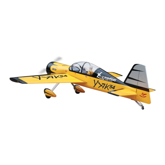
"Graphics and Specifications may change without notice".
Specifications
Wing span--------------------------------- 63.4 in --------------------- 161cm.
Wing area-------------------------------- 846 sq.in ------------- 54.6 sq.dm.
Weight------------------------------------- 8.4-9.9lbs ---------------3.8-4.5kg.
Length------------------------------------- 61.4 in ---------------------- 156cm.
Recommended engine size---------- .91-1.25 cu.in --------- 2-4stroke.
Radio System required 6 channel with 6 digital servos.
Flying skill level Intermediate/advanced.
Kit features.
•
Ready-made—minimal assembly & finishing required.
•
Ready-covered covering.
•
Photo-illustrated step-by-step Assembly Manual.
Made in Vietnam.
M A N U A L
M A N U A L
M A N U A L
M A N U A L
M A N U A L
20cc gasoline engine.
MS: 53
.
Advertisement
Table of Contents

Related Manuals for Seagull SEA53B


Summary of Contents for Seagull SEA53B
- Page 1 MS: 53 A S S E M B L Y A S S E M B L Y A S S E M B L Y A S S E M B L Y A S S E M B L Y M A N U A L M A N U A L M A N U A L...
-
Page 2: Fuselage Assembly
YAK 54. Instruction Manual. INTRODUCTION. Thank you for choosing the YAK 54 ARTF by SG MODELS . The YAK 54 was designed with the intermediate/advanced sport flyer in mind. It is a semi scale airplane which is easy to fly and quick to assemble. -
Page 3: Hinging The Ailerons
3) Slide the wing panel on the aileron until NOTE: To avoid scratching your new aero- there is only a slight gap. The hinge is now plane we suggest that you cover your work- centered on the wing panel and aileron. bench with an old towel. -
Page 4: Hinging The Elevator
YAK 54. Instruction Manual. 7) Repeat this process with the other wing panel, securely hinging the aileron in place. 8) After both ailerons are securely hinged, firmly grasp the wing panel and aileron to make sure the hinges are securely glued and cannot be pulled out. -
Page 5: Rudder Control Horn
CONTROL HORN M3 SCREW CONTROL HORN M3 Epoxy. ALUMINUM WASHER Aluminum Washer Epoxy Wing Aluminum Washer ALUMINUM WASHER M3 LOCK NUT M3 LOCK Epoxy. Wing Horizontal Stabilizer. 16mm Epoxy. 16mm Wing bottom. Aileron. Elevator control horn. ELEVATOR CONTROL HORN. RUDDER CONTROL HORN. Install the elevator control horn using the same method as with the aileron control horns. -
Page 6: Installing The Stopper Assembly
YAK 54. Instruction Manual. Mark and drill 4 holes for engine mount. M3 LOCK NUT Aluminum Washer CONTROL HORN M3 Fuselage. Aluminum Washer Diameter =5.5mm. M3 LOCK NUT M3 LOCK NUT Thread locker glue. CONTROL HORN M3 Aluminum Washer Rudder. Fuselage. -
Page 7: Fuel Tank Installation
4) Test fit the stopper assembly into the Balsa wood. tank. It may be necessary to remove some of the flashing around the tank opening using a modeling knife. If flashing is present, make sure none falls into the tank. 5) With the stopper assembly in place, the weighted pick-up should rest away from the rear of the tank and move freely inside the... -
Page 8: Installing The Main Landing Gear
YAK 54. Instruction Manual. Vent tube. wheel. wheel collar. Washer. Axle. nut. Fuel pick-up wheel Pant. tube. Fuel fill tube. Lite-Plywood block. Blow through one of the lines to ensure the fuel lines have not become kinked inside the fuel tank compartment. Air should flow through easily. -
Page 9: Mounting The Engine
2) Using the hardware provided, mount the Engine 2 stroke: main landing gear to the fuselage. M6 X 20mm. Machine Screw 4x30mm. MOUNTING THE ENGINE. 1) Place your engine onto the engine mount. Adjust the engine is centered of the edges of the engine case. - Page 10 YAK 54. Instruction Manual. COWLING. Mark point. Machine Screw 3x10mm. Paper tape guide. 1mm drill bit. 1.5mm wire (needle valve). Paper tape guide. Mark point. Trim and cut. Trim and cut.
-
Page 11: Installing The Switch
INSTALLING THE FUSELAGE SERVO. Left side. Engine 2 stroke: Remove covering. Rudder servo. 2) Install the rubber grommets and brass collets onto the elevator servo. Test fit the servo into the elevator servo mount. Throttle servo. Because the size of servos differ, you may need to adjust the size of the precut open- ing in the mount. -
Page 12: Horizontal Stabilizer
YAK 54. Instruction Manual. Pen. Remove covering. Switch. Remove covering. When cutting through the covering to remove it, cut with only enough pressure to only cut through the covering itself. Cutting into the balsa structure may weaken it. Switch. Remove covering. HORIZONTAL STABILIZER. -
Page 13: Vertical Stabilizer Installation
VERTICAL STABILIZER INSTALLATION. Remove covering. Rudder control horn. When cutting through the covering to re- move it, cut with only enough pressure to only cut through the covering itself. Cutting into the balsa structure may weaken it. Hinge. Hinge slot. C/A glue. - Page 14 YAK 54. Instruction Manual. String. Aileron Small weight. Servo. Electric wire. Wing rib. Wing. Small Weight. Small Weight. String. String. Attach the string to the servo lead and carefully thread it though the wing. AILERON PUSHROD HORN INSTALLATION Wing. 65mm. M3 clevis.
-
Page 15: Elevator Pushrod Installation
ELEVATOR PUSHROD INSTALLATION. Elevator pushrods assembly follow pictures below. Wing. 120mm. M3 lock nut. M3clevis. M3 lock nut. Aileron. 142mm. RUDDER PULL - PULL CABLE SYSTEM. See pictures below. Elevator control horn. Rudder control horn. M3 lock nut. Cable wire. Elevator Pushrod. - Page 16 YAK 54. Instruction Manual. Bottom. Elevator pushrod. Rudder pushrod. Fuselage bottom. Throttle. 70mm. Rudder. Bottom. Alumium trap. INSTALLING TAIL STRUT SUPPORT M3x10mm. The tail strut system assembly follow pic- tures below. M3x10cm(2pcs). Alumium trap. Vertical Fin. Horizontal Fin. Snap keeper. 180mm.
-
Page 17: Mounting The Tail Wheel
Horizontal Fin. Vertical Fin. M3x25 mm. M3x30 mm. M3x30 mm. MOUNTING THE TAIL WHEEL. See picture below. Spring. M3x25mm. M3x30mm. Tail landing gear. - Page 18 YAK 54. Instruction Manual. THROTTLE SERVO ARM INSTALLATION. ) Install adjustable servo connector in the servo arm. Tie wrap. Adjustable Servo connector. Servo arm. Receiver. 2) Install the rubber grommets and brass Antenna wire. collets onto the throttle servo. Test fit the servo into the throttle servo mount.
-
Page 19: Control Throws
Insert two wing panels as pictures below. BALANCING. 1) It is critical that your airplane be bal- anced correctly. Improper balance will cause your plane to lose control and crash. The cen- 7-8cm ter of gravity is locate back from the leading edge of the wing, measured at wing tip. - Page 20 YAK 54. Instruction Manual. E) Check the throttle. Moving the throttle INITIAL FLYING/SPORT FLYING stick forward should open the carburetor bar- rel. If it does not, flip the servo reversing switch Ailerons: 5/8” up 1/2” down on your transmitter to change the direction. Elevator: 3/4”...
Need help?
Do you have a question about the SEA53B and is the answer not in the manual?
Questions and answers