Table of Contents
Advertisement
FSC B15-1A Service Manual
SERVICE MANUAL
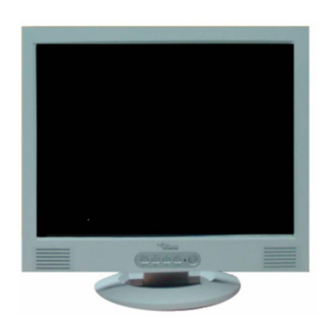
15" LCD Monitor
FSC B15-1A
THESE DOCUMENTS ARE FOR REPAIR SERVICE INFORMATION ONLY. EVERY REASONABLE
EFFORT HAS BEEN MADE TO ENSURE THE ACCURACY OF THIS MANUAL; WE CANNOT
GUARANTEE THE ACCURACY OF THIS INFORMATION AFTER THE DATE OF PUBLICATION AND
DISCLAIMS RE LIABILITY FOR CHANGES, ERRORS OR OMISSIONS.
1
Advertisement
Table of Contents

Related Manuals for Fujitsu Siemens Computers FSC B15-1A


Summary of Contents for Fujitsu Siemens Computers FSC B15-1A
-
Page 1: Service Manual
FSC B15-1A Service Manual SERVICE MANUAL 15” LCD Monitor FSC B15-1A THESE DOCUMENTS ARE FOR REPAIR SERVICE INFORMATION ONLY. EVERY REASONABLE EFFORT HAS BEEN MADE TO ENSURE THE ACCURACY OF THIS MANUAL; WE CANNOT GUARANTEE THE ACCURACY OF THIS INFORMATION AFTER THE DATE OF PUBLICATION AND... -
Page 2: Table Of Contents
FSC B15-1A Service Manual Table of Contents Table of Contents ---------------------------------------------------------------------------- 02 Revision List ----------------------------------------------------------------------------------- Monitor Specification --------------------------------------------------------------------- 2. LCD Monitor Description --------------------------------------------------------------- 3. Operation Instructions -------------------------------------------------------------------- 3.1 General Instructions ------------------------------------------------------------------06 3.2 Control Button ------------------------------------------------------------------------- 3.3 Adjusting The Picture ---------------------------------------------------------------- 4. - Page 3 FSC B15-1A Service Manual 5.3.1Main Board -----------------------------------------------------------------------1 5.3.2 Inverter/Power Board -----------------------------------------------------------17 6. Schematic ----------------------------------------------------------------------------------- 6.1 Main Board --------------------------------------------------------------------------19 6.2 Inverter/Power Board ---------------------------------------------------------------- 6.3 KeyPad Board ------------------------------------------------------------------------- 7. PCB Layout --------------------------------------------------------------------------------- Main Board -----------------------------------------------------------------------------24 Inverter/Power Board ----------------------------------------------------------------26 Keypad Board -------------------------------------------------------------------------27 8. Maintainability ------------------------------------------------------------------------------ 8.1 Equipments and Tools Requirements --------------------------------------------...
-
Page 4: Monitor Specification
FSC B15-1A Service Manual 1. MONITOR SPECIFICATIONS Driving system TFT Color LCD Size 38.1cm(15.0") Pixel pitch 0.297mm( H )x 0.297mm( V ) LCD Panel Viewable angle 130˚ (H) 90˚ (V) Response time (typ.) 25 ms Video Analog Sync. Type H/V TTL Separate and Composite Sync. -
Page 5: Lcd Monitor Description
FSC B15-1A Service Manual 2. LCD MONITOR DESCRIPTION The LCD MONITOR will contain an main board, an inverter/power board, keypad board and internal adapter which house the flat panel control logic, brightness control logic and DDC. The Inverter board will drive the backlight of panel and the DC-DC conversion. -
Page 6: Operating Instructions
FSC B15-1A Service Manual 3. OPERATING INSTRUCTIONS 3.1 GENERAL INSTRUCTIONS Press the power button to turn the monitor on or off. The other control buttons are located at front panel of the monitor. By changing these settings, the picture can be adjusted to your personal preferences. -
Page 7: Adjusting The Picture
FSC B15-1A Service Manual 3.3 ADJUSTING THE PICTURE To set the OSD menu, perform the following steps: Briefly press the SELCT/MENU button to activate the OSD menu. The main menu appears on the screen with icons for the setting functions. - Page 8 FSC B15-1A Service Manual Adjusting the brightness and contrast Calling the Brightness / Contrast setting window. Brightness Setting the brightness of the display With this function you change the brightness of the background lighting. Contrast Setting the contrast of the display With this function you modify the contrast of bright colour tones.
- Page 9 FSC B15-1A Service Manual Native = Original colour of the LCD display Custom colour = Setting user-defined colours In the user-defined setting you can change the colour ratios of the basic colours (red, green, blue) as required. Setting display of the OSD menu...
-
Page 10: Input/Output Specification
FSC B15-1A Service Manual 4. Input/Output Specification 4.1 Input Signal Connector Analog D-SUB Connector Meaning Meaning Video input red +5 V (DDC) Video input green Sync. ground Video input blue Ground Ground DDC-Data Ground H. sync Red video ground V. sync... -
Page 11: Power Supply Requirements
FSC B15-1A Service Manual 4.3 Power Supply Requirements 4.3.1 Input Requirements PARAMETER RANGE CONDITION Input Voltage 90 to 264VAC RMS Universal input full range Input Frequency 47 Hz to 63 Hz 110V AC 60Hz; 220V AC 50 Hz Input voltage 100 VAC RMS ;... -
Page 12: Panel Specification
FSC B15-1A Service Manual 4.4 PANEL SPECIFICATION (SEC XH-L01) 4.4.1 Panel Feature -High contrast ratio, high aperture structure -Wide viewing angle -High- speed response -XGA (1024 x 768 pixels) resolution -Display 16.2M colors -Low power consumption -4 CCFTS (Cold Cathode Fluorescent Tube) -
Page 13: Parameter Guide Line For Ccfl Inverter
FSC B15-1A Service Manual 4.4.4 Parameter guide line for CCFL Inverter The back-light system is an edge-lighting type with 4 CCFTS (Cold Cathode Fluorescent Tube) The characteristics of two lamps are shown in the following tables Ta=25± 2℃ ITEM SYMBOL... - Page 14 FSC B15-1A Service Manual...
-
Page 15: Software Flow Chart
FSC B15-1A Service Manual 5.2 Software Flow Chart... - Page 16 FSC B15-1A Service Manual 1) MCU initialize. 2) Is the eeprom blank ? 3) Program the eeprom by default values. 4) Get the PWM value of brightness from eeprom. 5) Is the power key pressed ? 6) Clear all global flags.
-
Page 17: Electrical Block Diagram
FSC B15-1A Service Manual 5.3 Electrical Block Diagram 5.3.1 Main Board... -
Page 18: Inverter/Power Board
FSC B15-1A Service Manual 5.3.2 Inverter/Power Board Inverter Block Diagram... - Page 19 FSC B15-1A Service Manual Power Block Diagram...
-
Page 20: Schematic
FSC B15-1A Service Manual 6. Schematic 6.1 Main Board MST8031B SCHEMATIC 62X115 FOR SEIMENS GNDR GNDR GNDG GNDG DDC_CLK VCC2.5 VCC3.3 VAA1 VAA2 VAA3 VAA4 DDC_DAT GNDB GNDB ST_DET1 HSYNC HSYNC ST_DET2 VSYNC VSYNC VCC2.5 VCC3.3 VAA1 VAA2 VAA3 CLK+... - Page 21 FSC B15-1A Service Manual CN301 DB15 FB301 1/16W R301 1/16W C304 0.047uF FB302 1/16W R302 1/16W C305 0.047uF FB303 1/16W R303 1/16W C306 0.047uF R304 1/16W C307 0.001uF PC5V R325 C301 C302 C303 VGA_CON ...
- Page 22 FSC B15-1A Service Manual PA[0..9] PA[0..9] LVA3P CON24A(PITCH 2.0) LVA3M LVACKP CN503 LVACKM LVB0M RXO0- RXO0+ LVB0P LVA2P LVB1M RXO1- RXO1+ LVB1P LVA2M LVB2M RXO2- RXO2+ LVB2P LVBCKM RXOC- RXOC+ LVBCKP LVA1P RXO3- RXO3+ LVB3M LVB3P LVA1M LVA0M RXE0- RXE0+...
-
Page 23: Inverter/Power Board
FSC B15-1A Service Manual VCC12V VCC12V C701 C702 C703 470uF/16V 470uF/16V 0.1uF/16V R702 1/16W U701 TDA7496L MUTE AUDIO_SD CN701 EAR_L R701 10K 1/16W C704 0.47uF/16V C705 470uF/16V OUT_L OUTL R703 C706 0.47uF/16V C707 470uF/16V OUT_R OUTR D701 1/16W... -
Page 24: Keypad Board
FSC B15-1A Service Manual Q203 SI4431DY-T1 C215 22pF/3KV CN201 +12V L201 R212 3.9K D201 R224 R225 R226 C201 C223 C202 Q202 C225 R214 SR24 D203 2K 2K 1/16W C216 CN202 150uF/25V 150uF/25V 0.1uF/25V DTA144WKA 1uF/25V 3.9K 1/16W RLZ11B... -
Page 25: Pcb Layout
FSC B15-1A Service Manual 7. PCB Layout 7.1 Main Board 715L1225-C... - Page 26 FSC B15-1A Service Manual...
-
Page 27: Inverter/Power Board
FSC B15-1A Service Manual 7.2 Inverter/Power Board 715L1063-1A... -
Page 28: Keypad Board
FSC B15-1A Service Manual 7.3 Keypad Board 715L1071-1-2 8. Maintainability 8.1 Equirement and Tools Requirement 1.)Voltmeter. 2.)Oscilloscope. 3) Pattern Generator. 4) DDC Tool with a IBM Compatible Computer. 5) Alignment Tool. 6) LCD Color Analyzer. 7) Service Manual. User Manual. -
Page 29: Trouble Shooting
FSC B15-1A Service Manual 8.2 Trouble Shooting 8.2.1 Main Board 1.NO SCREEN APPEAR Measured U021 pin 2 =2.5 V? eck Correspondent component. Measured U202 pin 2= 3.3V? Is there any shortage or cold Measured CN201pin 2 = 3.3V? Yes, all DC level exist Disconnected the Signal cable( Loose the Signal cable ),Is the screen show “No... - Page 30 FSC B15-1A Service Manual 2.PANEL-POWER CIRCUIT Check on PANEL U601 PIN25 check R207 should have response from 0V to 5V In normal operation, when LED =green, R207 When we switch the power switch from on to off should =0 v,...
- Page 31 FSC B15-1A Service Manual 4.U401-DATA Output NG , no transition Check U401MST8011B Signal output Replace MST8011B (U401) or PA0~PA9, PB0~PB9 replace MAINBOARD. Is the waveform ok If Main Board being replace , please do the DDC – content...
-
Page 32: Power/Inverter Board
FSC B15-1A Service Manual 8.2.2 Power/Inverter Board 1.) No power Check to CN102 Pin9 and pin10= 5V Check Interface board Check AC line volt 120V or 220V Change F901 , check BD901,Q903,IC901 Check the voltage of C904(+) Check bridge rectified circuit... - Page 33 FSC B15-1A Service Manual 2.) W / LED , No Backlight Check C201(+) =12V Change F902 Check D201/Q209/Q210 or D202/Q211/Q212 Check ON/OFF signal Check Interface board Check U201 pin9=12V Change Q201 or Q202 Check the pin1 of U201 have sawtooth wave Change U201 Check D201(-),D202(-) have the output of square wave at short time.
-
Page 34: Key Pad Board
FSC B15-1A Service Manual 8.2.3 KeyPad Board OSD is unstable or not working Connect Key Pad Is Key Pad Board connecting Board normally ? Replace Button Is Button Switch normally ? Switch Replace Key Pad Is Key Pad Board Normally ? -
Page 35: White-Balance, Luminance Adjustment
FSC B15-1A Service Manual 9. White-Balance, Luminance adjustment Approximately 30 minutes should be allowed for warm up before proceeding White-Balance adjustment. 1.、How to do the Chroma-7120 MEM .channel setting A、Reference to chroma 7120 user guide B、Use “ SC” key and “ NEXT” key to modify xyY value and use “ID” key to modify the TEXT description Following is the procedure to do white-balance adjust 2、Setting the color temp. - Page 36 FSC B15-1A Service Manual B、Adjust C1(6500) color-temperature 1、Switch the chroma-7120 to RGB-Mode (with press “MODE” button ) 2、Switch the MEM .channel to Channel 4( with up or down arrow on chroma 7120 ) 3、The LCD-indicator on chroma 7120 will show x = 313 ±10, y = 329 ±10, Y = 180 ±10 cd/m...
-
Page 37: Bom List
FSC B15-1A Service Manual 11. BOM List T560KSXHBSM8A CBPC560KSXM8 CONVERSION BOARD FOR T5 1 PCS KEPC560KM3 KEY BOARD FOR T560K*SNI 1 PCS PWPC5425B1 POWER BOARD 1 PCS 2L6008 1 SCREW 4 PCS 1 L 7 WOODEN PALLET 0.007 PCS 1 L 8 WOODEN PALLET 0.007 PCS... - Page 38 FSC B15-1A Service Manual 89L404C18N IS POWER CORD 插墙 FOR EUROP 1 PCS 95L8014 12 8 HARNESS 1 PCS 95L8018 24 2 HARNESS 60mm GREATLAND 1 PCS M1L 140 10 47 SCREW M4X10 4 PCS M1L 140 10 47 SCREW M4X10...
- Page 39 FSC B15-1A Service Manual C707 67L309L471 3 470UF+-20% 16V 1 PCS C708 67L309L471 3 470UF+-20% 16V 1 PCS CN701 88L 30210K PHONE JACK 1 PCS CN301 88L 35315F HS D-SUB 15PIN FEMALE 1 PCS 90L6059 1 散热片 FOR U701 1 PCS...
- Page 40 FSC B15-1A Service Manual R608 61L0603101 CHIPR 100 OHM +-5% 1/16 1 PCS R609 61L0603101 CHIPR 100 OHM +-5% 1/16 1 PCS R634 61L0603101 CHIPR 100 OHM +-5% 1/16 1 PCS R635 61L0603101 CHIPR 100 OHM +-5% 1/16 1 PCS...
- Page 41 FSC B15-1A Service Manual R317 61L0603203 CHIPR 20K OHM+-5% 1/16W 1 PCS R318 61L0603203 CHIPR 20K OHM+-5% 1/16W 1 PCS R323 61L0603203 CHIPR 20K OHM+-5% 1/16W 1 PCS R324 61L0603203 CHIPR 20K OHM+-5% 1/16W 1 PCS R313 61L0603222 CHIPR 2.2K OHM+-5% 1/16...
- Page 42 FSC B15-1A Service Manual C703 65L0603104 12 0.1UF +-10% 16V X7R 1 PCS C713 65L0603104 12 0.1UF +-10% 16V X7R 1 PCS C201 65L0603104 32 CHIP 0.1UF 50V X7R 1 PCS C203 65L0603104 32 CHIP 0.1UF 50V X7R 1 PCS...
- Page 43 FSC B15-1A Service Manual C403 65L0603220 31 CHIP 22PF 50V NPO 1 PCS C602 65L0603220 31 CHIP 22PF 50V NPO 1 PCS C604 65L0603220 31 CHIP 22PF 50V NPO 1 PCS C312 65L0603221 31 CAP:CER 220PF 5% 50V SM 1 PCS...
- Page 44 FSC B15-1A Service Manual D702 93L 64 32 LL4148 SMD 1 PCS D601 93L 6432V LL4148-GS08 0 PCS D701 93L 6432V LL4148-GS08 0 PCS D702 93L 6432V LL4148-GS08 0 PCS D301 93L 6433P BAV99 1 PCS D302 93L 6433P BAV99...
- Page 45 FSC B15-1A Service Manual CON20 33L8021 2D AC CONN.2P R/A 87210-0236 1 PCS CON20 33L8021 2D AC CONN.2P R/A 87210-0236 1 PCS CON20 33L8021 2D AC CONN.2P R/A 87210-0236 1 PCS 40L 45762412A CBPC LABEL 1.03 PCS 6 4500 RTV 胶...
- Page 46 FSC B15-1A Service Manual C922 67L 215102 3H 1000UF +-20% 16V 1 PCS C923 67L 215102 3H 1000UF +-20% 16V 1 PCS C922 67L215C102 3H EC LESR 1000UF16V HERME 0 PCS C923 67L215C102 3H EC LESR 1000UF16V HERME 0 PCS...
- Page 47 FSC B15-1A Service Manual J002 95L 90 23 TIN COATED 0 PCS J003 95L 90 23 TIN COATED 0 PCS J004 95L 90 23 TIN COATED 0 PCS J005 95L 90 23 TIN COATED 0 PCS J006 95L 90 23...
- Page 48 FSC B15-1A Service Manual R904 61L214Y10552T 1M,1/4W 1 PCS R905 61L214Y10552T 1M,1/4W 1 PCS R906 61L214Y10552T 1M,1/4W 1 PCS R907 61L214Y10552T 1M,1/4W 1 PCS FB901 71L 55 29 FERRITE BEAD 1 PCS ZD902 93L 39 5452T ZENER HZ12B2 1 PCS...
- Page 49 FSC B15-1A Service Manual R204 61L0603103 CHIPR 10K OHM +-5% 1/16 1 PCS R220 61L0603123 CHIP 12K OHM 1/16W 1 PCS R221 61L0603123 CHIP 12K OHM 1/16W 1 PCS R238 61L0603123 CHIP 12K OHM 1/16W 1 PCS R239 61L0603123 CHIP 12K OHM 1/16W...
- Page 50 FSC B15-1A Service Manual C910 65L0805102 32 CHIP 1000P 50VX7R 0805 1 PCS C202 65L0805104 22 0.1UF +-10% 25V X7R 080 1 PCS C204 65L0805104 22 0.1UF +-10% 25V X7R 080 1 PCS C205 65L0805104 22 0.1UF +-10% 25V X7R 080...
- Page 51 FSC B15-1A Service Manual D910 93L 60224 FCH10A10 0 PCS D911 93L 60235 FCQ10A06(F10P06Q) 1 PCS D911 93L 60236 FMB-26L 0 PCS M1L1730 8128 SCREW M3x8 2 PCS CN901 87L 501 12 CJ AC SOCKET 1 PCS CN901 87L 501 12 RF...
Need help?
Do you have a question about the FSC B15-1A and is the answer not in the manual?
Questions and answers