Table of Contents
Advertisement
FSC B17-1 Service Manual
SERVICE MANUAL
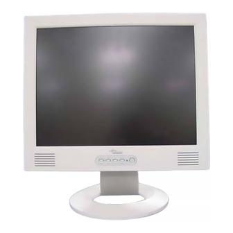
17" LCD Monitor
FSC B17-1
THESE DOCUMENTS ARE FOR REPAIR SERVICE INFORMATION ONLY. EVERY REASONABLE EFFORT
HAS BEEN MADE TO ENSURE THE ACCURACY OF THIS MANUAL; WE CANNOT GUARANTEE THE
ACCURACY OF THIS INFORMATION AFTER THE DATE OF PUBLICATION AND DISCLAIMS RE
LIABILITY FOR CHANGES, ERRORS OR OMISSIONS.
Advertisement
Table of Contents

Related Manuals for Fujitsu Siemens Computers FSC B17-1


Summary of Contents for Fujitsu Siemens Computers FSC B17-1
-
Page 1: Service Manual
FSC B17-1 Service Manual SERVICE MANUAL 17” LCD Monitor FSC B17-1 THESE DOCUMENTS ARE FOR REPAIR SERVICE INFORMATION ONLY. EVERY REASONABLE EFFORT HAS BEEN MADE TO ENSURE THE ACCURACY OF THIS MANUAL; WE CANNOT GUARANTEE THE ACCURACY OF THIS INFORMATION AFTER THE DATE OF PUBLICATION AND DISCLAIMS RE... -
Page 2: Table Of Contents
FSC B17-1 Service Manual Table of Contents Table of Contents -----------------------------------------------------------------2 1. MONITOR SPECIFICATIONS ----------------------------------------------------4 2. LCD MONITOR DESCRIPTION -----------------------------------------------5 3. OPERATING INSTRUCTIONS ------------------------------------------------6 3.1 GENERAL INSTRUCTIONS --------------------------------------------------6 3.2 CONTROL BUTTONS -----------------------------------------------------------6 3.3 ADJUSTING THE PICTURE --------------------------------------------------6 4. Input/Outpt Specification --------------------------------------------------------8 4.1 Input Signal Connector --------------------------------------------------------8... - Page 3 FSC B17-1 Service Manual 6.1 Main Board ----------------------------------------------------------------------19 6.2 Inverter/Power Board --------------------------------------------------------22 6.3 KeyPad Board -----------------------------------------------------------------24 7. PCB Layout -----------------------------------------------------------------------25 7.1 Main Board ---------------------------------------------------------------------25 7.2 Inverter/Power Board --------------------------------------------------------27 7.3 Keypad Board ------------------------------------------------------------------28 8. Maintainability --------------------------------------------------------------------28 8.1 Equirements and Tools Requirements ---------------------------------28 8.2 Trouble Shooting --------------------------------------------------------------29...
-
Page 4: Monitor Specifications
FSC B17-1 Service Manual 1. MONITOR SPECIFICATIONS Driving system TFT Color LCD LCD Panel Size 38.1cm(15.0") Pixel pitch 0.297mm( H )x 0.297mm( V ) Viewable angle 130˚ (H) 90˚ (V) Response time (typ.) 25 ms Video Analog/DVI-D Input Sync. Type H/V TTL Separate and Composite Sync. -
Page 5: Lcd Monitor Description
FSC B17-1 Service Manual 2. LCD MONITOR DESCRIPTION The LCD MONITOR will contain an main board, an inverter/power board, keypad board and internal adapter which house the flat panel control logic, brightness control logic and DDC. The Inverter board will drive the backlight of panel and the DC-DC conversion. -
Page 6: Operating Instructions
FSC B17-1 Service Manual 3. OPERATING INSTRUCTIONS 3.1 GENERAL INSTRUCTIONS Press the power button to turn the monitor on or off. The other control buttons are located at front panel of the monitor. By changing these settings, the picture can be adjusted to your personal preferences. -
Page 7: Adjusting The Picture
FSC B17-1 Service Manual 3.3 ADJUSTING THE PICTURE To set the OSD menu, perform the following steps: Briefly press the SELCT / MENU button to activate the OSD menu. The main menu appears on the screen with icons for the setting functions. - Page 8 FSC B17-1 Service Manual Setting the brightness of the display Auto Level With this function you can automatically set the contrast. Press the SELECT/MENU button to activate function. Adjusting size and position Calling the setting window Image adjust Adjusting the horizontal position H-Position With this function you move the picture to the left or to the right.
- Page 9 FSC B17-1 Service Manual Setting the horizontal position of the OSD menu H-Position With this function you move the OSD menu to the left or to the right. Setting the vertical position of the OSD menu V-Position With this function you move the OSD menu up or down.
-
Page 10: Input/Outpt Specification
FSC B17-1 Service Manual 4. Input/Outpt Specification 4.1 Input Signal Connector 4.1.1 Analog D-SUB Connector Meaning Meaning Video input red +5 V (DDC) Video input green Sync. ground Video input blue Ground Ground DDC-Data Ground H. sync Red video ground V. -
Page 11: Factory Preset Display Modes
FSC B17-1 Service Manual 4.2 Factory Preset Display Modes The following are the most frequently used of the preset operating modes: Horizontal frequency Refresh rate Screen resolution 31.5 kHz 70 Hz 720 x 400 31.5 kHz 60 Hz 640 x 480 37.5 kHz... -
Page 12: Power Supply Requirements
FSC B17-1 Service Manual 4.3 Power Supply Requirements 4.3.1 Input Requirements PARAMETER RANGE CONDITION Input Voltage 90 to 264VAC RMS Universal input full range Input Frequency 47 Hz to 63 Hz 110V AC 60Hz; 220V AC 50 Hz Input Current Less than 2.0 Amps RMS... -
Page 13: Panel Specification (Samsung )
FSC B17-1 Service Manual 4.4 PANEL SPECIFICATION (CPT) 4.4.1 Panel Feature -High contrast ratio, high aperture structure -TN(Twisted Nematic) mode -Wide viewing angle -High speed response -SXGA(1280 x 1024 pixels) resolution -Low power consumption -2 dual CCFTs(Cold Cathode Fluorescent Tube) -
Page 14: Parameter Guide Line For Ccfl Inverter
FSC B17-1 Service Manual 4.4.4 Parameter guide line for CCFL Inverter INVERTER MAX BRINGTHNESS (Vadj:5.0v), LOAD=80K X4(ROOM TEMPERATURE 25 4 ) ITEM SYMBOL MIN. TYP. MAX. UNIT REMARK Input voltage Vin 10.8 12 13.2 V Input current Iin 1700 2450 mA FOR 4 LOAD Output Current ... -
Page 15: Block Diagram
FSC B17-1 Service Manual 5. Block Diagram 5.1 Monitor Exploded View... -
Page 16: Software Flow Chart
FSC B17-1 Service Manual 5.2 Software Flow Chart... - Page 17 FSC B17-1 Service Manual 1) MCU initialize. 2) Is the eeprom blank ? 3) Program the eeprom by default values. 4) Get the PWM value of brightness from eeprom. 5) Is the power key pressed ? 6) Clear all global flags.
-
Page 18: Electrical Block Diagram
FSC B17-1 Service Manual 5.3 Electrical Block Diagram 5.3.1 Main Board LCD Interface (CN301) LVDS THC63LVDM83R (U301/U302) Scalar gm2120 (Include MCU,ADC,OSD) Flash Memory W39f010P-70B (U202) (U203) Hsync, EPR_SDA Vsync EPR_SCL DVI-I only Control EEPROM D-Sub Connector Interface 24C16 Connector (CN101) -
Page 19: Inverter/Power Board
FSC B17-1 Service Manual 5.3.2 Inverter/Power Board Inverter Block Diagram P a ra lle t-re s o n a n t V in B u c k C o n n e c to r in v e rte r... - Page 20 FSC B17-1 Service Manual Power Block Diagram PWPC7425A2 INTERNAL POWER CIRCUIT DIAGRAM...
-
Page 21: Schematic
FSC B17-1 Service Manual 6. Schematic 6.1 Main Board CN101 RX2-IN A_GND RX2- RX2+IN RX2+ SGND DDC_SCL_D DDCCLK DDC_SDA_D DDCDAT A_VSYNC RX1-IN RX1- RX1+IN RX1+ SGND DVI_5V ZD101 R101 10K MLL5232B 5.6V HOT_PLUG RX0-IN RX0- RX0+IN RX0+ SGND SGND RXC+IN... - Page 22 FSC B17-1 Service Manual +3.3V R403 RP402 CN403 JP403,JP404 Package +3.3V LED_GRN JP403 JP404 LED_ORG JP403 JP404 KEY_AUTO R405 KEY ENTER R404A 620(NC) KEY_RIGHT RP401 4.7K KEY LEFT KEY_RIGHT GPIO7 KEYON_OFF KEY ENTER R218 1K 0603 0603 VOL_OUT GPIO6 KEY_AUTO...
- Page 23 FSC B17-1 Service Manual MUTE +12V MUTE 2-26 modify 1/16W LL4148 LL4148 1/16W 1/16W 150uF/25v 150uF/25v 100nF C6 0 1/16W R2 470 Earphone(L) 470nF 470U 5.1K OUT(L) OUT(L) OUTL OUT(R) OUT(R) OUTR 5.1K 470nF 470U VOLUME STDBY C11 0 1/16W...
- Page 24 FSC B17-1 Service Manual RP212 1/16W OPB[0..7] P.5 A3.3V R240 OPB7 OPB6 PDEN D3.3V OPB5 OPB4 SPEC(150mA) R242 33 RP211 1/16W C234 C227 R241 OPB3 C231 C232 C233 C226 C228 C238 C239 C240 C241 C242 OPB2 0.1uF/16V 12/20 0.1uF/16V 0.1uF/16V 0.1uF/16V...
- Page 25 FSC B17-1 Service Manual 3.3V FB301 C300 C301 C302 C303 0.1uF/16V 0.1uF/16V 0.1uF/16V 10uF/16V U301 EPB[0..7] EPB0 LVDS_ON LVDS_EN TXIN0 PWRDWN EPB1 TXIN1 EPB2 TX0-E TXIN2 TXOUT0- EPB3 TX0+E TXIN3 TXOUT0+ EPB4 TX1-E TXIN4 TXOUT1- EPB5 TX1+E TXIN6 TXOUT1+ EPB6...
- Page 26 FSC B17-1 Service Manual A2.5V D3.3V A3.3V D2.5V FB501 FB502 +3.3V 3.3V FB503 600OHM 600OHM C504 C501 C502 C503 C505 C507 600OHM C508 47uF/16V 47uF/16V 0.1uF/16V 0.01uF/16V 0.1uF/16V 0.01uF/16V C509 C510 47uF/16V 0.1uF/16V 0.01uF/16V SOT-223 D3.3V U501 VOUT C514 SOT-223 +3.3V...
-
Page 27: Inverter/Power Board
FSC B17-1 Service Manual 6.2 Inverter/Power Board C0N102 ON/OFF ON/OFF R920 C920 1/2W 0.001uF/500V 33A8009-12L-H T901 D910 L903 20A/100V DB901 R906 C922 2KBP06M 1/4W R904 C905 R903 1000uF/16V C924 C926 1/4W 0.0015uF/2KV 100K R921 470uF/16V 0.1uF C904 1/2W C921 120uF/400V... -
Page 28: Keypad Board
FSC B17-1 Service Manual 6.3 KeyPad Board PHONEJACK SPKR L+ SPKR R+ OUT L+ OUT R+ HP R LED GRN# LED ORG# KEY AUTO LCD ONOFF KEY RIGHT KEY LEFT KEY MENU HP L HP L HP R OUT L+... -
Page 29: Pcb Layout
FSC B17-1 Service Manual 7. PCB Layout 7.1 Main Board... - Page 30 FSC B17-1 Service Manual...
-
Page 31: Inverter/Power Board
FSC B17-1 Service Manual 7.2 Inverter/Power Board... -
Page 32: Keypad Board
FSC B17-1 Service Manual 7.3 Keypad Board... -
Page 33: Maintainability
FSC B17-1 Service Manual 8. Maintainability 8.1 Equirements and Tools Requirement 1.) Voltmeter. 2.) Oscilloscope. 1.) Pattern Generator. 2.) DDC Tool with a IBM Compatible Computer. 3.) Alignment Tool. 4.) LCD Color Analyzer. 5.) Service Manual. 6.) User Manual. -
Page 34: Trouble Shooting
FSC B17-1 Service Manual 8.2 Trouble Shooting 8.2.1 Main Board 1.NO SCREEN APPEAR Measured U503 pin 2 = 2.5 V? Check Correspondent component. Measured U502 pin 2= 3.3V? Is there any shortage or cold solder? Measured U501pin 2 =3.3V? Yes.there have OSD show... - Page 35 FSC B17-1 Service Manual 2.PANEL-POWER CIRCUIT Check the PPWR panel power relative circuit, check R302 should have response from 0V to 5V Q301, Q302(pin 5,6,7,8) When we switch the power switch from on to off In normal operation, when LED =green, R302...
- Page 36 FSC B17-1 Service Manual 4.U203-DATA OUTPUT NG , no transition Measured DCLK(R240) DVS, DHS (pin 117,116 from U203 ) Is the waveform ok? DCLK around 48 MHZ , DVS=60.09Hz , DHS around 80 KHz ?(refer to input Replace GM2120 (U203) or replace signal=640x480@60 Hz 31k, and LED is MAINBOARD.
-
Page 37: Power/Inverter Board
FSC B17-1 Service Manual 8.2.2 Power/Inverter Board 1.) No power Repeating the start voltage... - Page 38 FSC B17-1 Service Manual 2.) W / LED , No Backlight Check Q209/Q210/C213 or Q211/Q212/C214...
-
Page 39: Keypad Board
FSC B17-1 Service Manual 8.2.3 KeyPad Board OSD is unstable or not working Connect KeyPad Board Is KeyPad Board connecting normally ? Replace Button Switch Is Button Switch normally ? Replace KeyPad Board Is KeyPad Board Normally ? Check Main Board... -
Page 40: White-Balance, Luminance Adjustment
FSC B17-1 Service Manual 9. White-Balance, Luminance adjustment Approximately 30 minutes should be allowed for warm up before proceeding white balance adjustment. Before started adjust white balance ,please setting the Chroma-7120 MEM. channel 1 to 6500 color, MEM. channel 2 to 7200 color, and MEM. -
Page 41: Edit Content
FSC B17-1 Service Manual 17 Switch the chroma-7120 to RGB-mode (with press “MODE” button ) 18 switch the MEM.channel to Channel 03 ( with up or down arrow on chroma 7120 ) 19 The lcd-indicator on chroma 7120 will show x = 296... - Page 42 FSC B17-1 Service Manual...
- Page 43 FSC B17-1 Service Manual...
- Page 44 FSC B17-1 Service Manual...
- Page 45 FSC B17-1 Service Manual...
- Page 46 FSC B17-1 Service Manual...
- Page 47 FSC B17-1 Service Manual...
- Page 48 FSC B17-1 Service Manual...
- Page 49 FSC B17-1 Service Manual...
- Page 50 FSC B17-1 Service Manual...
- Page 51 FSC B17-1 Service Manual...
- Page 52 FSC B17-1 Service Manual...
- Page 53 FSC B17-1 Service Manual...
- Page 54 FSC B17-1 Service Manual...
- Page 55 FSC B17-1 Service Manual...
Need help?
Do you have a question about the FSC B17-1 and is the answer not in the manual?
Questions and answers