Table of Contents
Advertisement
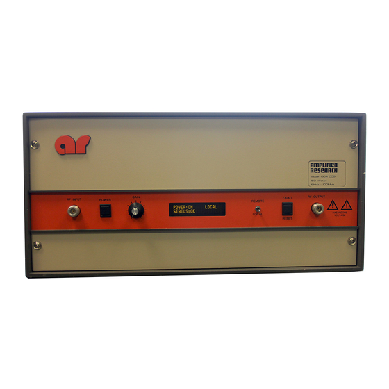
Model 150A400
SECTION I:
1.1
1.2
1.3
SECTION II:
2.1
2.2
2.2.1
2.2.2
SECTION III:
3.1
3.2
3.3
3.4
3.5
3.6
SECTION IV:
4.1
4.2
4.3
4.3.1
4.3.2
4.3.3
4.3.4
4.3.5
4.3.6
SECTION V:
5.1
5.2
5.3
TABLE OF CONTENTS
GENERAL INFORMATION
General Description ..................................................................1-1
Power Supplies.........................................................................1-1
Specifications ...........................................................................1-1
OPERATING INSTRUCTIONS
General............................................................................2-1
Amplifier Operation ..........................................................2-2
Local Operation........................................................................2-2
Remote Operation.....................................................................2-2
THEORY OF OPERATION
Introduction ..............................................................................3-1
Driver Amplifier Section............................................................3-1
Final Amplifier Section ..............................................................3-1
Power Supply ...........................................................................3-2
Fault Board ..............................................................................3-2
A3 Gain Control........................................................................3-2
MAINTENANCE
General Maintenance Information ..............................................4-1
Disassembly Procedures ...................................................4-1
Troubleshooting ........................................................................4-2
Front Panel Vacuum Fluorescent Display (VFD) Doesn't Indicate
"Power On" ...........................................................................4-2
Unit Cannot be Operated Remotely............................................4-3
Thermal Fault ...........................................................................4-3
Interlock Fault ..........................................................................4-4
Voltage/Amplifier Faults............................................................4-4
Low or No Power Output (DC Tests)........................................4-5
REPLACEABLE PARTS
Introduction ..............................................................................5-1
Ordering Information.................................................................5-1
Non-Listed Parts ......................................................................5-1
TABLE OF CONTENTS (
) iii
CONTINUED
Manual Text
Advertisement
Table of Contents

Subscribe to Our Youtube Channel
Related Manuals for AR 150A400


Summary of Contents for AR 150A400
- Page 1 Model 150A400 Manual Text TABLE OF CONTENTS SECTION I: GENERAL INFORMATION General Description ..............1-1 Power Supplies.................1-1 Specifications ................1-1 SECTION II: OPERATING INSTRUCTIONS General................2-1 Amplifier Operation ............2-2 2.2.1 Local Operation................2-2 2.2.2 Remote Operation..............2-2 SECTION III: THEORY OF OPERATION Introduction ................3-1 Driver Amplifier Section............3-1 Final Amplifier Section ..............3-1...
- Page 2 Level of Maintenance ...............6-1 ARRANTIES IMITATION OF IABILITIES LIST OF FIGURES Model 150A400 Front Panel............. 2-2 Model 150A400 Rear Panel............2-2 LIST OF TABLES IEEE-488 Device Address Selection ......... 2-5 Remote Error Codes/Messages ..........2-6 RS-232 Connector Pin-Outs ............. 2-7...
-
Page 3: Power Supplies
OWER UPPLIES The 150A400 contains four switching power supplies. The input voltage range to these supplies is 90-132 VAC and 180-264 VAC, 50/60 Hz universal or selected automatically. The operator does not have to switch or change anything on the 150A400 when changing the AC input voltage. The power consumption is a nominal 800 watts. - Page 4 OPERATING INSTRUCTIONS ENERAL Operation of the Model 150A400 broadband RF amplifier is simple. The input signal, whether swept or fixed in frequency, is fed into the jack marked “INPUT”, and the amplifier’s output signal is taken from the jack labeled “OUTPUT”. The unit is turned on by activating the power switch marked “POWER”. In the event of a unit malfunction, protection is provided by an internal circuit breaker.
-
Page 5: Amplifier Operation
Adjust gain control if necessary. 2.2.2.1 Introduction This subsection describes remote operation of the Model 150A400 amplifier by utilizing either the IEEE-488 parallel interface or the RS-232 serial interface and a controlling device, such as a bus controller or a personal computer (PC). - Page 6 2.2.2.2 Selecting Remote Operation The Model 150A400 can be placed in the remote operation mode at any time by switching the FUNCTION switch on the front panel to the REMOTE position. In this mode, control is transferred to the selected remote interface and all front panel controls are inoperative with the exception of the FUNCTION switch.
- Page 7 “Service Request” (SRQ) line is asserted; the operator can then perform a serial poll operation. The Model 150A400 error code (in binary) is contained in the returned serial poll status byte (STB). These error codes are defined in Table 2-2.
- Page 8 Model 150A400. The CTS line can be used as a “handshake” line to inform the Model 150A400 when it is permissible to send information. If the CTS line is de- asserted in the middle of a transmission, the character in the process of being transmitted will be completed and further transmission will halt until the CTS line is re-asserted.
- Page 9 2.2.2.8 Remote Commands The following commands are available to the user for remote communication and operation of the Model 150A400. In the descriptions of these commands, a lower-case “x” is used to signify a numeric value or parameter. REV B...
- Page 10 2.2.2 Remote Operation (continued) 2.2.2.8 Remote Commands (continued) 2.2.2.8.1 Power On/Off Controls the power on/off state of the Model 150A400. Syntax: Px Parameters: 0 = power off 1 = power on Example: To turn the power on, send the following command: P1<LF>...
-
Page 11: Driver Amplifier Section
THEORY OF OPERATION INTRODUCTION The Model 150A400 amplifier consists essentially of 2 push-pull output stages of broadband MOSFET transistors driven by a driver amplifier. Overall power gain of the amplifier is a minimum of +52dB for 1 milliwatt input. Input and output impedance matching circuits are utilized to provide optimum power transfer of the RF signal when the amplifier is connected to source and load impedance of 50 ohms. -
Page 12: Power Supply
Instruction Set Computing (RISC) microcontroller that can quickly and reliably perform all front panel control and monitoring tasks, thereby allowing real-time control to the Model 150A400 via either remote bus. Besides being reported remotely, all amplifier faults are continuously monitored and indicated via the unit’s front panel VFD. -
Page 13: Troubleshooting
MAINTENANCE GENERAL MAINTENANCE INFORMATION The Model 150A400 should require very little maintenance, since it is a relatively simple instrument. It is built with etched circuit wiring and solid state devices which should ensure long, trouble -free life. However, should trouble occur, special care must be taken in servicing to avoid damage to the devices or the etched circuit board. -
Page 14: Unit Cannot Be Operated Remotely
OF ± ± 20 VOLTS, THIS WILL RESULT IN TRANSISTOR GAT FAILURE. Troubleshooting Troubleshooting the Model 150A400 in a logical manner can speed the solution to a problem. The settings of potentiometers (“pots”), capacitors (“caps”), or other variables should not be disturbed until other problems have been eliminated. - Page 15 Model 150A400 Manual Text 4.3.1.2 Check the FUNCTION switch on the unit’s front panel; it must be set to the LOCAL position in order to operate the front panel POWER switch. Check the circuit breaker on the unit’s rear panel; it must be set to the “1” (“ON”) position.
- Page 16 Model 150A400 Manual Text 4.3.3 Thermal Fault (Schematic Diagram No 1010877) During a Thermal Fault, the front panel VFD should read “THERMAL FAULT.” REV B...
- Page 17 4.3.4 Interlock Fault (Schematic Diagram No. 1010877) The Model 150A400 is equipped with an interlock connector, which is located on the rear panel. The interlock circuit can be used to sense the openings of doors to screen rooms, test chambers, and so forth, and to turn off RF energy when these doors are opened.
-
Page 18: Voltage/Amplifier Faults
Model 150A400 Manual Text 4.3.5 Voltage/Amplifier Faults (Schematic Diagram Nos. 1010877) The model 150A400 fault circuits sense voltage faults from PS1 (+15V) and PS2 (+15V) and PS4 (+28V). They also sense an over current fault in the final amplifier stage. 4.3.5.1 Power Supply Faults (Schematic Diagram 1010877). - Page 19 Model 150A400 Manual Text REV B...
Need help?
Do you have a question about the 150A400 and is the answer not in the manual?
Questions and answers