
Related Manuals for AR 40S6G18A-L


Summary of Contents for AR 40S6G18A-L
- Page 1 Operating and Service Manual 40S6G18A-L Model 10050984 Part Number Serial Number 160 Schoolhouse Road, Souderton, PA 18964 • 215-723-8181 • Fax 866-859-0582 • www.arworld.us...
- Page 3 REGULATION (EC) 1907/2006 of the European Parliament and of the Council of 18 December 2006 concerning the Registration, Evaluation, Authorization and Restriction of Substances of Very High Concern Chemicals (SVHC) Supporting documentation is held by AR RF/Microwave Instrumentation’s Quality department in Pennsylvania, United States. Place of issue:...
- Page 5 Instructions for European EMC Conformity WARNING It is the responsibility of the user of this equipment to provide electromagnetic shielding, filtering and isolation which is necessary for EMC compliance to Directive 2014/30/EU. The equipment must therefore be operated in a shielded area which provides a sufficient level of attenuation to meet the radiated emissions and immunity specifications.
- Page 7 The caution symbol denotes a potential hazard. Attention must be given to the statement to prevent Your AR equipment may have more than one power supply cable. Use damage, destruction, or harm. only approved power cable(s). If you have not been provided with a Dangerous voltages are present.
- Page 8 EQUIPMENT CONTAINING LASERS risk of serious injury due to unsafe AR Field Probes (FL/PL Series) and Field Analyzers (FA product handling should be a fundamental Series) are Class 1 laser products containing embedded consideration every user.
- Page 9 Zur Vermeidung von Personen- oder Sachschäden gilt BEVOR SIE DAS GERÄT ANSCHLIESSEN es, die Hinweise zu beachten. Ihre AR-Ausrüstung hat möglicherweise mehr als ein Stromversorgungskabel. Gefährliche elektrische Spannungen sind vorhanden. Verwenden Sie nur zugelassene Stromkabel. Falls Sie kein Stromkabel oder Höchste Vorsicht ist geboten.
- Page 10 Die meisten Geräte müssen während des Versands, der Montage und des Gebrauchs LASER-INFORMATION transportiert werden. Jeder Nutzer sollte sich AR - Feldsonden (FL/PL-Serie) und Feldanalysatoren (FA-Serie) über das Risiko von schweren Verletzungen sind Laserprodukte der Klasse 1 mit eingebetteten Klasse-4- durch unsachgemäße...
- Page 11 électrode de mise à la Votre équipement AR peut disposer de plus d’un câble d’alimentation terre de protection. électrique. Utilisez uniquement un ou des câbles d’alimentation approuves.
- Page 12 éliminer le risque injustifié de blessures causées par le levage est fournie par les méthodes de travail de NIOSH (publication Les sondes de champ AR (série FL/PL) et les analyseurs de n° 94-110) disponibles sur : champ (série FA) sont des produits laser de classe 1 contenant des lasers intégrés de classe 4.
- Page 13 Er zijn gevaarlijke elektrische spanningen aanwezig. Wees uiterst voorzichtig. VOOR HET OPZETTEN VAN DE STROOM Uw AR-apparatuur kan meer dan een netvoedingskabel bezitten. Gebruik alleen goedgekeurde netvoedingskabel(s). Koopt een Wijst op een terminal aan die bedoeld is voor aansluiting netvoedingskabel die is goedgekeurd voor gebruik in uw land als u...
- Page 14 APPARAAT DAT LASERS BEVAT distributie, de assemblage en het gebruik moeten worden behandeld, moet het risico AR-terreinsondes (FL/PL-serie) en terreinanalysatoren (FA- op ernstig letsel als gevolg van een serie) zijn laserproducten van klasse 1 met ingesloten onveilige behandeling van het product een klasse 4-lasers.
-
Page 15: Table Of Contents
TABLE OF CONTENTS TABLE OF CONTENTS ....................i GENERAL INFORMATION ................1 General Description ....................1 Power Supplies ....................... 1 Specifications ......................1 OPERATING INSTRUCTIONS ................ 5 General ........................5 Amplifier Front and Rear Panels ................6 Interface Identification ................... 6 2.3.1 Local Controls ...................... - Page 16 Model 40S6G18A-L Remote Control Interfaces ..................18 2.9.1 GPIB (IEEE-488) Communications ..............18 2.9.2 RS-232 Communications ..................18 2.9.3 Fiber-Optic Serial Communications ..............19 2.9.4 USB Communications ..................19 2.9.5 Ethernet Communications ..................20 2.10 Remote Commands ....................20 2.10.1 Power On / Off ..................... 21 2.10.2 RF On / Off ......................
- Page 17 Model 40S6G18A-L FIGURES Model 40S6G18A-L Front Panel ................6 Model 40S6G18A-L Rear Panel ................6 Typical Gain Response @ 0dBm Input ..............36 Typical Gain Response @ -20 dBm Input ............36 Typical Response: A4 to RF Output Gain ............37 Typical A1A2 Driver Amp Response ..............
-
Page 19: General Information
USB, or Ethernet interface. POWER SUPPLIES The Model 40S6G18A-L contains a switching power supply. The input voltage range to the power supply is 90–264 VAC, 47-440Hz, selected automatically. PS1 is a multiple output supply. The main +27, +12, -12, +10 and -5 volts DC supplies voltage to the RF low level and final stages. - Page 20 Model 40S6G18A-L Rev B...
- Page 21 Built-in fault monitoring and protection • Remote control: Ethernet, USB, GPIB, fiber-optic serial, RS-232 The Model 40S6G18A-L is a solid-state, This is a multiple purpose amplifier. • Modular design for easy Class A design, self-contained, liquid- The low level of spurious signals and...
- Page 22 Model 40S6G18A-L • 40 W • 6 - 18 GHz Electrical Specifications Parameter Symbol Minimum Typical Maximum Unit Rated Power Output (6 - 18 GHz) PSAT >115 Input for Rated Output Power Output @ 1 dB Compression P1dB >95 Power Output @ 3 dB Compression P3dB >110...
- Page 23 Model 40S6G18A-L • 40 W • 6 - 18 GHz Mechanical Specifications Parameters Unit 50.2 x 20.6 x 63.2 Dimensions (With Cabinet) (W x H x D) 19.8 x 8.1 x 24.9 48.3 x 18.0 x 62.5 Dimensions (No Cabinet) – 4U for 19” Rack 19.0 x 7.1 x 24.6...
- Page 24 Model 40S6G18A-L • 40 W • 6 - 18 GHz Envelope Drawing 40S6G18-L with Cabinet 40S6G18-L without Cabinet AR RF/Microwave Instrumentation • 160 Schoolhouse Rd, Souderton, PA 18964 • 215-723-8181 • info@arworld.us • www.arworld.us • ISO 9001:2015 Certified • ISO 17025:2017 Accredited...
-
Page 25: Specifications
Model 40S6G18A-L • 40 W • 6 - 18 GHz TYPICAL PSAT POWER @ 0dBm INPUT TYPICAL POWER @ P3dB COMPRESSION AR RF/Microwave Instrumentation • 160 Schoolhouse Rd, Souderton, PA 18964 • 215-723-8181 • info@arworld.us • www.arworld.us • ISO 9001:2015 Certified •... - Page 26 Model 40S6G18A-L • 40 W • 6 - 18 GHz TYPICAL POWER @ P1dB COMPRESSION TYPICAL SMALL SIGNAL GAIN @ -20dBm INPUT AR RF/Microwave Instrumentation • 160 Schoolhouse Rd, Souderton, PA 18964 • 215-723-8181 • info@arworld.us • www.arworld.us • ISO 9001:2015 Certified •...
- Page 27 HARMONIC @ 40 WATTS OUTPUT AR RF/Microwave Instrumentation • 160 Schoolhouse Rd, Souderton, PA 18964 To order AR Products, call: 215.723.8181. For an applications engineer, call: 800.933.8181. Direct to Service call: 215.723.0275 or email: service@arworld.us For Faxing Orders: 866.859.0582 (Orders Only Please) info@arworld.us Approved for public release by AR RF/Microwave Instrumentation ISO 9001:2015 Certified •...
-
Page 29: Operating Instructions
2. OPERATING INSTRUCTIONS GENERAL Operation of the Model 40S6G18A-L broadband amplifier is simple. The input signal, whether swept or fixed in frequency, is fed into the jack marked INPUT and the amplifier output signal is taken from the jack labeled OUTPUT. -
Page 30: Amplifier Front And Rear Panels
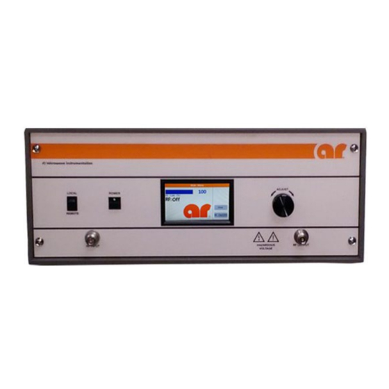
Model 40S6G18A-L AMPLIFIER FRONT AND REAR PANELS Figure 2-1 shows the front panel of the Model 40S6G18A-L Broadband Microwave Amplifier. Figure 2-2 shows the rear panel of the Model 40S6G18A-L Broadband Microwave Amplifier. Figure 2-1. Model 40S6G18A-L Front Panel Figure 2-2. Model 40S6G18A-L Rear Panel INTERFACE IDENTIFICATION This section describes all external interfaces used to operate the amplifier via the control software. -
Page 31: Adjust Knob
Model 40S6G18A-L 2.3.1.3 Adjust Knob The ADJUST knob is used to set the value of the RF Gain between 0 and 100 percent. The ADJUST knob can be rotated both clockwise and counterclockwise 360 degrees. 2.3.1.4 Touch Screen The touch screen is a color LCD that can accept single touch events from soft blunt objects such as a human finger. -
Page 32: Local User Interface
Model 40S6G18A-L LOCAL USER INTERFACE This section describes the user interface used during local operation of the amplifier as it pertains to the control system. 2.4.1 Menu Map Below is a menu map for the amplifier. The screens depicted are only example screens. The actual values and settings will be different on the actual amplifier depending on user settings and operating conditions. -
Page 33: User Screen
Model 40S6G18A-L 2.4.3 User Screen The User screen presents the user with the revision levels of all the firmware that is running on all the main control system components. For the Switch Breakout Board (SBB) assemblies, only the piggy-back assembly firmware is listed. -
Page 34: Gpib Address Screen
Model 40S6G18A-L 2.4.5 GPIB Address Screen The GPIB address screen is used to select the GPIB address. To get here from the Main Menu, touch the User menu button followed by the I/O menu button and finally the GPIB menu button. -
Page 35: Key Beep Screen
Model 40S6G18A-L 2.4.7 Key Beep Screen The Key Beep screen allows the user to turn on or off the audible beep that occurs when a valid touch event takes place. This setting is only stored in volatile memory and will be lost when power to the unit is cycled. -
Page 36: Fault Screen
Model 40S6G18A-L 2.4.9 Fault Screen The Fault screen will appear anytime that a fault condition is met. The name of the fault is shown toward the center of the screen. With the Local/Remote switch set to either LOCAL or REMOTE positions, a Reset button will appear allowing local resetting of the fault condition. -
Page 37: Power Off, Rf Off
Model 40S6G18A-L 2.5.1 Power Off, RF Off 2.5.1.1 Description AC power is applied, the Power button has not been pressed (LED status indicator not lit). The control system is waiting for a user action or a remote command. 2.5.1.2 State Change Requirements No change. -
Page 38: Control Lines
Model 40S6G18A-L CONTROL LINES This section defines all required control lines to be utilized by the control software and any actions (faults or alerts) that the control software must perform. In the tables below, indicate the NO ACTION STATES (or the correct operating states) of each line required and any actions that are required if the line is out of bounds. -
Page 39: Connector J5
Model 40S6G18A-L 2.6.1.3 Connector J5 Lines 3, 4: Supplies +3.3 Vdc via a 10kOhm pull-up resistor Lines 1-4: Guaranteed operation up to +30 Vdc Lines 3, 4: 0 Vdc or +3.3 Vdc TTL Inputs & OD Outputs: Guaranteed operation up to +5 Vdc... -
Page 40: Fault Definition
Model 40S6G18A-L FAULT DEFINITION This section is used to define all faults that can occur and their source. Use the Control Line column to define what active control line generates the fault or use the text Internal for an internally generated fault from the control system (i.e ‘Internal 485 bus error’). -
Page 41: Fault Control Actions (Utilized On Amplifiers 1000 Watts And Above)
Model 40S6G18A-L NO-FAULT CONTROL ACTIONS (UTILIZED ON AMPLIFIERS 1000 WATTS AND ABOVE) This section describes all no-fault actions taken by the controls system and their sources. Use the Control Line column to define what active control line generates the fault or use the text Internal for an internally generated fault from the control system (i.e., ‘Internal 485 bus error’). -
Page 42: Remote Control Interfaces
Model 40S6G18A-L REMOTE CONTROL INTERFACES This section describes remote operation of the amplifier using the provided General Purpose Interface Bus (GPIB), RS-232 serial port, fiber-optic serial ports, Universal Serial Bus (USB), and Ethernet port. All ports are always active, however only one port may be used at a time. -
Page 43: Fiber-Optic Serial Communications
Core Size: 50um (minimum) to 200um (recommended) Connector Type: This port can be used in conjunction with a serial to fiber-optic or USB to fiber-optic interface, such as an AR IF7001 USB to Fiber-Optic interface. NOTE: The IF7001 device uses SMA connectors, so a fiber-optic cable is needed with ST connectors on one end and SMA connectors on the other. -
Page 44: Ethernet Communications
Once installed, the DeviceInstaller™ utility will scan the network and find all connected Lantronix Ethernet devices. This list of found devices will include any connected AR Ethernet devices. By selecting one of the connected devices from the list, its IP address and subnet mask can be changed along, with several other settings. -
Page 45: Power On / Off
Model 40S6G18A-L 2.10.1 Power On / Off This command controls the power state. No other command will be accepted until the POWER:ON command has been issued. It is good practice to wait a minimum of two (2) seconds before polling the status after issuing the POWER:ON command. -
Page 46: Identity Query
Model 40S6G18A-L 2.10.5 Identity Query This command queries the amplifier for its identity response. *IDN? Query: AR-RF/MICROWAVE-INST,<model>,<firm rev><LF> Response Format: The model designation of the amplifier. <model>: <firm rev>: The firmware revision of the control software. To query the identity of the amplifier, send the following command: Example: *IDN?<LF>... -
Page 47: Hex Character To Binary Bits Conversion Table
Model 40S6G18A-L Amplifier State Response Table Description State Notes Position -- Not Used -- -- Not Used -- <char 1> -- Not Used -- Response to Local/Remote position Remote Control 0 = Disabled, 1 = Enabled REMOTE Power Status 0 = OFF, 1 = ON... -
Page 48: Operating Hours (Rf On) Query
Model 40S6G18A-L 2.10.8 Operating Hours (RF ON) Query This command queries the total hours spent with the RF enabled. Query: OH=<hours><LF> Response Format: The total hours with RF Enabled (0 to 100000), padded with spaces to always <hours>: be 6 digits wide. -
Page 49: Sbb (Piggyback) Firmware Query
Model 40S6G18A-L 2.10.12 SBB (Piggyback) Firmware Query This command queries the firmware of the piggyback SBB assembly. *SBB? Query: SBB_SW_REV<revision><LF> Response Format: Where: x is the firmware revision. The revision of the SBB assembly. <revision>: Example: To query the piggyback SBB firmware revision, send the following command: *SBB?<LF>... - Page 50 Model 40S6G18A-L Rev B...
-
Page 51: Theory Of Operation
3. THEORY OF OPERATION INTRODUCTION The Model 40S6G18A-L RF amplifier consists of a 6.0–18 GHz RF amplifier assembly. The RF amplifier assembly consists of a Pre-Amplifier (Pre-Amp), a Driver Amplifier (Driver Amp), and a 40-watt output module. The power supply section consists of an AC input filter with a circuit breaker switch, a switching power supply, and a regulator circuit. -
Page 52: Power Supply
Model 40S6G18A-L POWER SUPPLY There are two power supplies in the 40S6G18A-L amplifier. Power supply PS1 is a switching supply that automatically sets the AC input circuits to the correct connections for the line voltage 90-132 and 180-250 VAC input ranges 50/60 Hz. The outputs of +24, +12 and -12 volts are used primarily in the A1A1 preamp module, control panel A12A1 and interface board A14. -
Page 53: Cooling System
Model 40S6G18A-L COOLING SYSTEM Information on the coolant used in the 40S6G18A-L: www.koolance.com Manufacturer: Koolance ( Manufacturer Part No: LIQ-702 Safety Data Sheet, reference: Koolance SDS-LIQ-702 Coolant Fluid Maximum pressure that the fluid is under is 15.6 Psi. The amount of fluid is ~300ml (the volume of the reservoir). - Page 54 Model 40S6G18A-L Rev B...
-
Page 55: Maintenance
4. MAINTENANCE GENERAL MAINTENANCE INFORMATION The Model 40S6G18A-L requires very little maintenance since it is a relatively simple instrument. It is built with thin film substrate etched circuit wiring and solid-state devices that will ensure long, trouble free life. However, should trouble occur special care must be taken in servicing to avoid damage to the devices or the thin film circuitry. -
Page 56: Troubleshooting
GaN and MMIC’s and other ESD-sensitive devices. Troubleshooting the Model 40S6G18A-L in a logical manner can speed the solution to a problem. The settings of potentiometers (pots), capacitors (caps), or other variables should not be disturbed until other problems have been eliminated. -
Page 57: Power On Indication Doesn't Display On Front Panel When Power Switch Is Depressed (Schematic 10050809)
<0.1V when S1 is depressed. S1 is normally open; it is closed only when it is depressed. The amplifier should change state every time the POWER switch is depressed. 8. If all voltages are correct and the unit still does not operate, contact AR to arrange for repair or replacement of the A12A1 Control/Fault Board. -
Page 58: Interlock Fault (Schematic 10050809)
RF energy when these doors are opened. NOTE: The Model 40S6G18A-L is shipped with a mating connector, which has a jumper between Pins 1 and 8, installed in the rear panel interlock connector. The unit will not operate unless the interlock circuit is closed. -
Page 59: Low Or No Power Output (Dc Tests) (Schematic 10050809)
Pin 6, 7 ±0.5V 8. The Model 40S6G18A-L’s typical gain response at 0dBm input and –20dBm input is shown in Figures 4-1 and 4-2. The actual gain may vary considerably from that shown in Figure 4-1, but should be > 43.5 dB. Figure 4-2 should be > 45 dB. -
Page 60: Typical Gain Response @ 0Dbm Input
Model 40S6G18A-L Figure 4-1. Typical Gain Response @ 0dBm input Figure 4-2. Typical Gain Response @ -20 dBm Input Rev B... -
Page 61: Typical A1A2 Driver Amp Response
Model 40S6G18A-L 9. Remove the coaxial cable between the output of the A1A2 Driver Amp, the input of the A4 40-watt module. The typical response from the input of the A4 40-watt module to the RF output connector on the unit’s front panel is shown in Figure 4-3. -
Page 62: Typical A1A1 Pre-Amp Response
Model 40S6G18A-L 12. If the A1A2 Driver Amp is normal, check the A1A1 Pre-Amp. The gain of the A1A1 Pre-Amp should be approximately 1-2 dB with the gain control at maximum. The typical A1A1 Pre-Amp response is shown in Figure 4-5. - Page 63 These modules are not field-repairable and should never be opened outside of AR’s Microelectronics Lab. The modules in these product lines have a security label on two sides of the modules between the housing and lid/cover. If the security label is removed and or cut, the warranty of the module will be voided.
Need help?
Do you have a question about the 40S6G18A-L and is the answer not in the manual?
Questions and answers