
Subscribe to Our Youtube Channel
Related Manuals for Campbell T107


Summary of Contents for Campbell T107
- Page 1 T107 Weather Station Revision: 5/12 C o p y r i g h t © 1 9 9 3 - 2 0 1 2 C a m p b e l l S c i e n t i f i c ,...
- Page 3 Warranty “PRODUCTS MANUFACTURED BY CAMPBELL SCIENTIFIC, INC. are warranted by Campbell Scientific, Inc. (“Campbell”) to be free from defects in materials and workmanship under normal use and service for twelve (12) months from date of shipment unless otherwise specified in the corresponding Campbell pricelist or product manual.
- Page 4 (435) 227-9106. Campbell Scientific is unable to process any returns until we receive this form. If the form is not received within three days of product receipt or is incomplete, the product will be returned to the customer at the customer's expense.
-
Page 5: Table Of Contents
T107 Weather Station Table of Contents PDF viewers: These page numbers refer to the printed version of this document. Use the PDF reader bookmarks tab for links to specific sections. 1. Preparation and Siting ..........1-1 1.1 Siting and Exposure................1-1 1.1.1 Wind Speed and Direction ............ - Page 6 T107 Weather Station Table of Contents 2.5 Communication Peripherals ..............2-22 2.5.1 Direct Connect to T107 Station..........2-22 2.5.2 Phone Modem ................2-24 2.5.2.1 Internal Installation............2-24 2.5.2.2 External Installation............2-25 2.5.3 Short-Haul Modem..............2-25 2.5.3.1 Internal Installation............2-26 2.5.3.2 External Installation............2-27 2.5.4 RF450 900 MHz, 1 Watt Spread Spectrum Radio ....
- Page 7 1.2-1A. Cut Flap Packing Tape ..............1-3 1.2-1B. Shipping Box Packaging ............... 1-3 1.2-2. T107 with the Met One 034B-ETM Wind Sensor, Top Layer..1-4 1.2-3. T107, Bottom Layer ................. 1-4 1.5-1. Magnetic Declination for the Contiguous United States ....1-7 1.5-2.
- Page 8 2.4-14. Position of Sensor Bulkhead Connectors ........2-20 2.4-15. Connecting Sensor Cabling to Enclosure ........2-21 2.5-1. Close-up of the terminals and 9-pin ports in the T107 (battery not shown).................. 2-23 2.5-2. Phone Modem Mounting and Connections (battery not shown) ..2-24 2.5-3.
- Page 9 T107 Weather Station Table of Contents B.2-2. Both Strut Clamps and Brackets on T107 Pole .......B-5 B.2-3. Top Clamp Hook Side Up ...............B-6 B.2-4. Enclosure Mounted on T107 Pole ...........B-7 B.2-5. Enclosure Locking Mechanism ............B-8 B.2-6. Mounted Solar Panel................B-9 B.2-7. Procedure for installing and connecting battery ......B-11 E-1.
- Page 10 T107 Weather Station Table of Contents...
-
Page 11: Preparation And Siting
Section 1. Preparation and Siting 1.1 Siting and Exposure CAUTION If any part of the weather station comes in contact with power lines, you could be killed. Contact local utilities for the location of buried utility lines before digging or driving ground rods. -
Page 12: Temperature And Relative Humidity
Cut the tape around the remaining flaps BUT only cut one layer deep. Lift up the cardboard flaps exposing the top layer of foam as shown in Figure 1.2-1B. ⇒ Check contents against invoice and shipping checklist. Contact Campbell Scientific immediately about any shortages. -
Page 13: A. Cut Flap Packing Tape
Section 1. Preparation and Siting Cut Lower Flap Edge First FIGURE 1.2-1A. Cut Flap Packing Tape Top Packing Foam Layer Middle Packing T107, Foam Layer Top Layer T107, Bottom Packing Bottom Layer Foam Layer FIGURE 1.2-1B. Shipping Box Packaging... -
Page 14: T107 With The Met One 034B-Etm Wind Sensor, Top Layer
Wind Set Instruction Instruction Manual Manual Cardboard Cardboard Containing Wind Vane FIGURE 1.2-2. T107 with the Met One 034B-ETM Wind Sensor, Top Layer Mounting Template Grounding Wire 2-Piece Pole Grounding and AC Transformer and Enclosure Desiccant Packs Lightning Rod and Cabling... -
Page 15: Outdoors
Locate suitable site (Section 1) • Prepare concrete base (Section 2) • T107 Installation: ⇒ Place instrumentation enclosure on the ET pole. Slide enclosure to the top of the pole and secure with correct orientation (Section 2.3). 1.3 Tools Required Tools required to install and maintain a weather station are listed below. -
Page 16: Tools For Instrumentation And Maintenance
Direct burial armored cable may be required for rocky soils or rodents (Anixter p/n F-02P22BPN (phone 847.677.2600)) or equivalent type cable (see Figure 2.1-1). RF450 Antenna for the T107 station (14205 Yagi antenna recommended). PS24 Power Supply and #18520 Hanger Kit if not using ac power (see Appendix B). -
Page 17: Determining True North For Wind Vane Orientation
Section 1. Preparation and Siting 1.5 Determining True North for Wind Vane Orientation Magnetic declination, or other methods to find True North, should be determined prior to installing the weather station. True North is usually found by reading a magnetic compass and applying the correction for magnetic declination*; where magnetic declination is the number of degrees between True North and Magnetic North. -
Page 18: Web Calculator
Section 1. Preparation and Siting FIGURE 1.5-2. Declination Angles East of True North Are Subtracted From 0 to Get True North FIGURE 1.5-3. Declination Angles West of True North Are Added to 0 to Get True North 1.5.1 Web Calculator Since magnetic declination fluctuates with time, it should be determined each time the wind sensor orientation is adjusted. - Page 19 Section 1. Preparation and Siting A positive declination is east, while a negative declination is west. The declination in this example is 12º 24′ or 12.4º. As shown in Figure 1.5-1, the declination for Logan, UT is east, so True North for this site is 360 – 12.4, or 347.6 degrees.
- Page 20 Section 1. Preparation and Siting EPA, (1989). Quality Assurance Handbook for Air Pollution Measurement Systems, EPA Office of Research and Development, Research Triangle Park, North Carolina 27711. 1-10...
-
Page 21: Hardware Installation
CAUTION: Do not fit the 3 meter ET Tower sections together until the appropriate time. Once attached, they cannot be detached. The ET Tower provides a support structure for mounting the T107 weather station components. Figure 2.1-1 shows a typical ET Tower installation option. The tower is designed to withstand winds of 100 mph. -
Page 22: Base Foundation
Section 2. Hardware Installation 2.1 Base Foundation 2.1.1 Supplied Components (3) 5/8 inch Anchor L-Bolts (9) 5/8 inch Nuts (1) Anchor Template Refer to Section 1 for components supplied by installer and bring components. 2.1.2 Installation 1. The ET Tower attaches to a user supplied concrete foundation constructed as shown in Figure 2.1-2. -
Page 23: Cement Pad
Section 2. Hardware Installation SIDE VIEW FORM TOP VIEW 2" FORM WIRE NORTH ANCHOR BOLT 24" 24" SMALL CAVITY CEMENT PAD 24" FORM WIRE TEMPLATE FIGURE 2.1-2. ET Tower Base Installation Conduit Anchor Bolt FIGURE 2.1-3. Cut-Away View Shows Anchor Bolt and Conduit Placement in Cement Pad... -
Page 24: Ac Power Installation
Connect the power plug to the connector marked “Power” on the back of the enclosure. See Figure 2.4-17. NOTE The AC power supply option for older T107 stations included a 120 VAC to 16 VAC step-down transformer instead of the 100 to 240 VAC to 24 VDC power supply. Appendix E provides information for installing an AC power system that includes the step-down transformer. - Page 25 Section 2. Hardware Installation they are put together. If a little more force is necessary to put the two halves together, then get a small block of scrap wood and a hammer. Set the pole upright on a grassy area or have someone hold the pole horizontally.
-
Page 26: Transparent View Shows Raising And Grounding The Et Tower
Section 2. Hardware Installation ET Tower 4 AWG Wire Leveling Ground Rod Concrete Foundation Anchor Bolt Swept Elbow Conduit FIGURE 2.2-1. Transparent View Shows Raising and Grounding the ET Tower 4 AWG Wire Ground Rod FIGURE 2.2-2. Close up of Ground Rod and 4 AWG Cable... -
Page 27: Tower Grounding
Section 2. Hardware Installation 2.2.3 Tower Grounding 2.2.3.1 Supplied Components (1) 5 foot 4 AWG Ground Cable (1) Copper Ground Lug, Bolt (1) Ground Rod, Clamp 2.2.3.2 Grounding Procedure Ground the tower as shown in Figures 2.2-1 and 2.2-2. 1. Place the ground rod clamp on the ground rod. Secure it about 3 inches from the top. -
Page 28: Enclosure
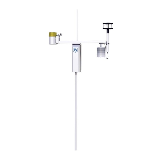
Logan, Utah MADE IN USA Ground FIGURE 2.3-1. T107 Instrumentation Mounted on the ET Tower 2.3.1 Enclosure Installation 1. Mount the ET enclosure on the ET Tower as shown in Figure 2.3-2. Remove the front lid. Remove the connector cover from the back of the ET enclosure by loosening the Phillips screw at the bottom of the cover. -
Page 29: Crossarm And Sensor Installation
Adjust the bolts at the base of the pole to vertically level the top section of the mounting pole. Install the T107 Sensor Arm after the ET Enclosure is mounted on the ET Tower. You may need to temporarily remove the communications option. -
Page 30: T107 Sensor Arm Mounting
Section 2. Hardware Installation Screws FIGURE 2.4-1. T107 Sensor Arm Mounting 1) Remove the front lid and the protective connector cover from the back of the ET enclosure by loosening the one Phillips screw at the bottom of the cover. -
Page 31: Rh And Temperature Radiation Shield
Section 2. Hardware Installation 2.4.3 RH and Temperature Radiation Shield 1. Remove the two Phillips screws taped underneath the crossarm. 2. Remove the yellow shipping cap from off the end of the temperature/relative humidity sensor. See Figures 2.4-2 and 2.4-3. Remove Yellow Cap FIGURE 2.4-2. -
Page 32: Temperature/Relative Humidity Sensor Without Yellow Protective Cap
Section 2. Hardware Installation Temp/RH with Cap Removed FIGURE 2.4-3. Temperature/Relative Humidity Sensor without Yellow Protective Cap 3. Insert the temperature/relative humidity into the gill radiation shield until it stops or a “click” is heard. 4. Attach the gill radiation shield to the underside of the crossarm using the two Phillips screws from step 1. -
Page 33: Wind And Rh/Temperature Sensor Installation
Section 2. Hardware Installation Temp/% RH Gill Radiation Shield Phillips Mounting Screws FIGURE 2.4-4. Wind and RH/Temperature Sensor Installation Wind Vane Counter Weight Shoulder Screw South UTION ENTIOMETER Alignment ENT 5mA FACE SOUTH Sticker Mounting Alignment Pipe Screw FIGURE 2.4-5. 034B Mounting to Pipe 2-13... -
Page 34: Gill Windsonic 2-D Ultrasonic Wind Sensor (Wind Sensor Option -Gw)
Jumper is set at the factory if Gill WindSonic is ordered with the station. When the WindSonic1-ET is added to the T107, a jumper setting must be changed. The procedure to change the jumper follows: 1. Remove the cover of the enclosure. -
Page 35: Screws That Secure The Electronics Cover
Section 2. Hardware Installation Loosen Screws FIGURE 2.4-6. Screws that Secure the Electronics Cover 4. Remove the electronics cover to expose the PCB (see Figure 2.4-7). Lift Here FIGURE 2.4-7. Removal of the Electronics Cover 2-15... -
Page 36: Attachment To Sensor Arm
Section 2. Hardware Installation 5. Move the jumper at the top of connector PC board so that it is placed over the center and right pins (see Figure 2.4-8). New Jumper Position FIGURE 2.4-8. Jumper Set for WindSonic1 6. Replace electronics cover. 7. -
Page 37: Gill Windsonic Mounting Shaft
Section 2. Hardware Installation FIGURE 2.4-9. Gill WindSonic Mounting Shaft 3. Slide the connector and cable up through the center of the mounting shaft. Plug the cable into the Gill WindSonic sensor. The connector has a key and needs to be pushed in then rotated clockwise to lock it in place. See Figure 2.4-10. -
Page 38: Rain Gage
Section 2. Hardware Installation 4. Center the Gill WindSonic over the three threaded screw holes on the mounting shaft and screw it in place using the three Phillips screws taken off the shaft in step 1. 5. Slide the shaft and sensor back through the U-bolt. Align the sensor with north by pointing the small colored dot on outer edge of the bottom of the sensor so it faces true north. -
Page 39: Pyranometer
Section 2. Hardware Installation 2.4.7 Pyranometer Level the pyranometer as indicated in Figure 2.4-12. Adjust the three leveling screws until the bubble level indicates plumb. Remove the red or green shipping cap from the pyranometer. See Figure 2.4-13. Leveling Screws FIGURE 2.4-12. -
Page 40: Sensor Connections
Section 2. Hardware Installation 2.4.8 Sensor Connections Sensor schematics are provided in Section 4.3.1. 1. Each sensor cable plug attaches to a unique bulkhead connector as shown in Figure 2.4-14. The sensor cables are individually marked to match up with the sensor labeling on the back of the enclosure. WARNING The 034B Wind Sensor plugs into the connector labeled WS/WD. -
Page 41: Connecting Sensor Cabling To Enclosure
Section 2. Hardware Installation NOTE It’s very important that each plug is completely seated on to the connector and the locking ring turned ¼ revolution clockwise. Failure to seat the plug completely could cause corrosion and water damage to both the enclosure and the sensor cable. Notice how the sensor caps are slid between the connector and NOTE the one above in Figure 2.4-15. -
Page 42: Sensor Verification And Clock Set
CS I/O port leaving the RS-232 port free for direct communication with a laptop or desktop computer using a standard RS-232 serial cable. The CR1000 datalogger used in the T107 station can speak with more than one device at a time allowing troubleshooting to be done in the field with a laptop while remote communication devices are accessing the station. - Page 43 RJ-11 patch cord radio via the 10588 ribbon cable Connects with Rad Connects with a modem’s 4-wire laptop via an RS-232 patch cable serial cable FIGURE 2.5-1. Close-up of the terminals and 9-pin ports in the T107 (battery not shown). 2-23...
-
Page 44: Phone Modem
FIGURE 2.5-2. Phone Modem Mounting and Connections (battery not shown) 2.5.2.1 Internal Installation If the phone modem was ordered with the T107, you can skip NOTE this section and go directly to the External Installation section. For installation inside the ET Enclosure, the following components are... -
Page 45: External Installation
Section 2. Hardware Installation 2. Connect the modem 9-pin port to the ET Enclosure CS I/O port with the P/N 10588 ribbon cable supplied with the ET Enclosure (see Figure 2.5-1 and 2.5-2). 3. Connect the modem RJ-ll jack to the ET Enclosure RJ-11 jack with the RJ-ll patch cord (see Figure 2.5-2). -
Page 46: Internal Installation
FIGURE 2.5-3. Short-haul modem mounting and connection 2.5.3.1 Internal Installation NOTE If the short haul modem was ordered with the T107, you can skip this section and go directly to the External Installation section. For installation inside the ET Enclosure, the following components are... -
Page 47: External Installation
Section 2. Hardware Installation Install the short-haul modems as shown in Figure 2.5-3 and 2.5-4. 1. Mount the Rad / SC932C mounting bracket into the ET Enclosure with the three pre-threaded screws provided. 2. Connect the Rad Modem and SC932C. Strap them into the mounting bracket under the Velcro strap. -
Page 48: Rf450 900 Mhz, 1 Watt Spread Spectrum Radio
Section 2. Hardware Installation NOTE The splice and wire nut must be completely immersed into the silicon gel inside the splice tube to be waterproof. 2) Mount the surge protector box to a flat surface within 5 feet of the PC's serial port. -
Page 49: Power Considerations
AC power is recommended when using RF450 radios with the station. A 10 watt solar panel can be used but days without sunlight and winter months with little sunlight should be considered. The T107 station comes with a 7 amp-hour battery that is NOT designed to handle deep discharge. Discharging the battery below 11 Vdc may require battery replacement. -
Page 50: Internal Installation
Section 2. Hardware Installation 2.5.4.3 Internal Installation If the RF450 radio was ordered with the T107, you can skip this NOTE section and go directly to the External Installation section. The following components are provided in the RF450 radio kit for installation... -
Page 51: External Installation
Section 2. Hardware Installation 3. Connect the long 9-pin female end of the 10588 ribbon cable to the CS I/O port on the RF450 radio. Screw the connector to the radio using the provided two screws. See Figures 2.5-6. 10588 Ribbon Cable FIGURE 2.5-6. -
Page 52: Loosely Wire Tie Antenna Cable
Section 2. Hardware Installation FIGURE 2.5-7. Loosely Wire Tie Antenna Cable FIGURE 2.5-8. Loosely Drape Antenna Cable over Back of Enclosure 2-32... -
Page 53: Slide Antenna Bracket U-Bolt Around Back Of The Pole
Section 2. Hardware Installation 3. Use the 2.125 stainless steel U-bolt to attach the adjustable angle mounting bracket to the pole. Depending on the size of the antenna position the bracket directly below, or above, the enclosure top mounting bracket. The top of an omni directional antenna should not be higher than the top of the lightning rod. -
Page 54: Antenna Bracket Mounted To Pole
Section 2. Hardware Installation FIGURE 2.5-10. Antenna Bracket Mounted to Pole 4. Mount the saddle bracket to the adjustable angle mount bracket by inserting the ends of the bracket through the quarter circle notches. Put a flat washer, lock washer, and a silicon bronze nut, in that order, on the ends of the saddle bracket. -
Page 55: Yagi Antenna Mounted To Saddle Bracket
Section 2. Hardware Installation NOTE Only rotate enclosure if needed to allow aiming of the Yagi antenna to the base antenna. Keep solar radiation sensor towards the South as much as possible. Rotate wind sensor to realign as needed. 5. Use the following procedure to install the 14205 Yagi antenna for the RF450. -
Page 56: Wire Tie Antenna Cable To Yagi Antenna And To Pole
Section 2. Hardware Installation iii. Adjust the antenna cable at the BNC connector so the cable cover fits over all the sensor cables as well as the antenna cable. You may have to gently bend the antenna cable to put a 90° bend by the BNC connector end of the cable. -
Page 57: Base Radio Installation
Section 2. Hardware Installation Wire Tie Wire Tie FIGURE 2.5-14. Wire Tie Locations for Omni Antenna Installation 2.5.4.5 Base Radio Installation The base radio kit comes with the following items. (1) 10873 RS-232 Serial Data Cable with 6 feet of cable (1) 15966 Wall Adapter: 100 to 240 Vac, 50-60 Hz Input to 12 Vdc 80 0mA Output with 6 feet of cable. -
Page 58: Base Rf450 Installation
Section 2. Hardware Installation Attach the SMA connector on the antenna to the RF450 radio. Remove the strip covering the adhesive on the antenna and stick it vertically to a window. Attach the serial cable from the calling computer’s serial port to the port marked “RS-232”... -
Page 59: Lightning Rod Installation
Section 2. Hardware Installation 2.6 Lightning Rod Installation Install lightning rod as shown in Figure 2.6-1 and 2.6-2. 1. Carefully mount the lightning rod clamp to the top of the pole (see Figure 2.6-1). Position the clamp so it won’t interfere with the connector cover. FIGURE 2.6-1. -
Page 60: Grounding To Lightning Rod Clamp
Section 2. Hardware Installation FIGURE 2.6-2. Grounding to Lightning Rod Clamp 3. Strip 2.54 cm (1”) from both ends of the 9” (23 cm) piece of 10 AWG green ground wire. Insert one end into the enclosure ground lug located at the top back of the enclosure. -
Page 61: Solar Panel Installation
Section 2. Hardware Installation 2.7 Solar Panel Installation FIGURE 2.7-1. Solar Panel Mounting and Cabling a) Mount the solar panel to the tower using the mounting brackets as shown in Figure 2.7-1. Mount the solar panel to the tower so it faces south (northern hemisphere). -
Page 62: Side View Of Solar Panel Shows Tilt Angle
Section 2. Hardware Installation Site Latitude Tilt Angle (α) 0 to 10 degrees 10 degrees 11 to 20 Latitude + 5 degrees 21 to 45 Latitude + 10 degrees 46 to 65 Latitude + 15 degrees >65 80 degrees α FIGURE 2.7-2. -
Page 63: Battery Installation
The charge light is not effected by the switch. Switching on the power supply without a charging voltage will run the battery down. Figure 2.8-2 shows factory wiring between the PS100 and the enclosure. FIGURE 2.8-2. PS100 to T107 Enclosure Wiring 2-43... -
Page 64: Restraining Cables And Sealing/Desiccating Enclosure
Section 2. Hardware Installation 2.9 Restraining Cables and Sealing/Desiccating Enclosure 2.9.1 Restraining Cables 1. Loosely wire tie power, communication, and grounding cable to the wire tie harness at the top of the back of the station. Do NOT clip back the wire tie at this time. -
Page 65: Sealing And Desiccating The Enclosure
Section 2. Hardware Installation FIGURE 2.9-2. Connector Cover in Place 6. Tighten down the wire ties holding cabling to the wire tie harness and clip off any excess. See Figure 2.9-2. 2.9.2 Sealing and Desiccating the Enclosure The ET Enclosure is supplied with two desiccant packs. The desiccant maintains a low humidity in the enclosure to minimize the chance of condensation on the instrumentation. -
Page 66: Desiccant Installation
Section 2. Hardware Installation 2) Be sure to close the enclosure hasp securely. A padlock may be used on the latch for extra security. Desiccant FIGURE 2.9-3. Desiccant Installation 2-46... -
Page 67: Et Software
A variety of different software packages are available to work with the T107 station. This section introduces software packages that can be used with the T107 station. It is not the goal to fully explain capabilities of each package. All software packages mentioned below come with extensive help files. - Page 68 Section 3. ET Software...
-
Page 69: Maintenance, Troubleshooting, And Schematics
Section 4. Maintenance, Troubleshooting, and Schematics 4.1 Maintenance Proper maintenance of the T107’s components is essential to obtain accurate data. Equipment must be in good operating condition, which requires a program of regular inspection and maintenance. Routine and simple maintenance can be accomplished by the person in charge of the weather station. -
Page 70: Sensor Maintenance
Section 4. Maintenance, Troubleshooting, and Schematics Desiccant packs may be ordered in quantity of 20 individually sealed packs at a time (item# 6714) or by the individual pack (item# 4905). Campbell Scientific does have a $50.00 minimum charge. Any orders under $50.00 require a $15.00 handling fee. - Page 71 Section 4. Maintenance, Troubleshooting, and Schematics 6 months • Replace 034B-ET’s anemometer bearings and reed switch if operating under harsh conditions, such as constant high winds, blowing dust, and/or salt spray contamination. 1 year • Replace 034B-ET wind speed (anemometer) bearings (item #3648). Contact your local Toro distributor for service.
-
Page 72: Procedure For Removing Rh Chip
Section 4. Maintenance, Troubleshooting, and Schematics 2 years • Replace 034B-ET’s vane potentiometer if needed (call for part number and price). Contact your local Toro distributor. • Replace enclosure gasket if necessary. Contact your local Toro distributor. 3 years • Send the solar radiation sensor (pyranometer) for calibration. -
Page 73: Cr1000M Module
SRAM when the module is not powered. The CR1000M does not draw power from the lithium battery while it is powered by a 12 VDC supply. In an T107 stored at room temperature, the lithium battery should last approximately 10 years (less at temperature extremes). -
Page 74: Troubleshooting
E. Cycle the power to the datalogger by switching the PS100 power supply to “OFF”, then to “ON” or disconnecting and reconnecting the battery plug. Keypad should power up and the Campbell Scientific logo and text appears on the display. -
Page 75: Nan Or ±Inf Displayed In A Variable
Section 4. Maintenance, Troubleshooting, and Schematics 25-pin serial port: computer end modem end 9-pin serial port: computer end modem end F. Make sure the communication device at the computer is properly configured and cabled (Section 2.5). G. Call your local Toro distributor if still no response. 4.2.3 NAN or ±INF Displayed in a Variable A. -
Page 76: Nan Or ±Inf Stored In A Data Table
Section 4. Maintenance, Troubleshooting, and Schematics 4.2.5 NAN or ±INF Stored in a Data Table A. Something is wrong with the datalogger and/or sensor(s) if Short Cut or VisualWeather was used to create the station program. Make sure the sensor is plugged into the correct bulkhead connector. If CRBasic is used to create the station program verify channel assignments and multipliers. - Page 77 Section 4. Maintenance, Troubleshooting, and Schematics TABLE 4.2-1. Multi-Point Network LED Status Master Slave Repeater Condition Carrier Transmit Clear to Carrier Transmit Clear to Carrier Transmit Clear to Detect (TX) Send Detect (TX) Send Detect (TX) Send (CD) (CTS) (CD) (CTS) (CD) (CTS)
-
Page 78: Gill Windsonic1-Et Diagnostic Diagnostic Codes
Section 4. Maintenance, Troubleshooting, and Schematics Radios not networked together, not communicating: 1. Check the baud rate of all RF450s; they should be the same. 2. Check Network IDs of all RF450s; they should be the same. 3. Check Frequency Key Number of all RF450s; they should be the same unless two branches of the network are operating in a parallel manner. -
Page 79: Schematics Of Connectors
Section 4. Maintenance, Troubleshooting, and Schematics TABLE 4.2-2. Gill WindSonic Diagnostic Codes Diagnostic Status Comment Okay All okay Axis 1 Failed Insufficient samples, possible path obstruction Axis 2 Failed Insufficient samples, possible path obstruction Both Axis Failed Insufficient samples, possible path obstruction NVM error Nonvolatile Memory checksum failed ROM error... -
Page 80: Sensor Schematics
Section 4. Maintenance, Troubleshooting, and Schematics 4.3.1 Sensor Schematics Schematics of T107 sensors and associated connectors are provided in Figures 4.3-1 through 4.3-7 for help in troubleshooting. Temp/RH Connector Air Temperature and Relative Humidity Datalogger Sensor Relative Humidity (0-1VDC) Air Temperature (0-1VDC) -
Page 81: Schematic Of 034B-Lc Wind Speed And Direction Probe And Connector Ws/Wd
Section 4. Maintenance, Troubleshooting, and Schematics Wind Speed and Wind Direction Sensor Connector 10K OHM Datalogger Excitation Wind Direction WS/WD 1K OHM Signal Return 10K OHM Potentiometer Analog Ground Pulse Wind Speed Magnetically Activated Reed Switch Ground Shield FIGURE 4.3-2. Schematic of 034B-LC Wind Speed and Direction Probe and Connector WS/WD Temp/Sonic Temperature or Gill... -
Page 82: Schematic Of Cs305-Et Solar Radiation Sensor And Connector Solar Radiation
Section 4. Maintenance, Troubleshooting, and Schematics Solar Radiation Connector Apogee Datalogger Solar Radiation Solar Radiation Sensor Sensor 10 to 20 OHMS 450-650 OHMS Not Used Not Used Not Used Shield FIGURE 4.3-4. Schematic of CS305-ET Solar Radiation Sensor and Connector Solar Radiation NOTE The T106 used a Licor LI200X-ET Solar Radiation Sensor with OHM readings of 450 to 650. -
Page 83: Schematic Of Te525-Et Rain Sensor And Connector Rain (Precip)
Section 4. Maintenance, Troubleshooting, and Schematics Connector Tipping Rain Bucket Rain (Precip) Not Used Not Used Not Used Datalogger Pulse Magnetically Activated Reed Switch Ground Shield FIGURE 4.3-5. Schematic of TE525-ET Rain Sensor and Connector Rain (Precip) 4-15... -
Page 84: Schematic Of Connector Sdi-12
Section 4. Maintenance, Troubleshooting, and Schematics Temperature or Soil Volumetric Water Content Connector Datalogger CS616 Signal Return Temperature Signal Return TEMP CS616 Temperature Excitation CS616 +12V Supply +12V CS616 Control Ground FIGURE 4.3-6. Schematic of 107-LC or 108-LC Temperature Probe or CS616-LC Soil Volumetric Water Content Sensor and Connector Temp/CS616 SDI-12 or Temperature... -
Page 85: Power Schematics
Section 4. Maintenance, Troubleshooting, and Schematics 4.3.2 Power Schematics 16-19 VAC or 16-24 VDC Solar Panel Power PS100 Charger/Regulator (Solar Panel+) Charge Black Charge (Solar Panel-) Power Note: PS100 Charger/Regulator is not sensitive to polarity. FIGURE 4.3-8. Schematic of Solar Panel and Connector Power 4.3.3 Communication Modems Schematics Short-Haul or Phone Modem Connector... - Page 86 Section 4. Maintenance, Troubleshooting, and Schematics 4-18...
-
Page 87: T107 Maintenance Log
Appendix A. T107 Maintenance Log Station Installation Date: __________________ CLEAN/INSPECT RAIN GAGE SENSOR CLEAN/INSPECT RAIN GAGE SENSOR (Recommended - Weekly) (Recommended - Weekly) Date OK/Comments Date OK/Comments... -
Page 88: Enclosure
Appendix A. T107 Maintenance Log REPLACE WIND SPEED BEARINGS AND CLEAN/INSPECT SOLAR RADIATION SENSOR REED SWITCH (Recommended - Monthly) (Recommended - Yearly) Date OK/Comments Date OK/Comments REPLACE RH CHIP (P/N 9598) IN THE HMP60-ET TEMP/% RH SENSOR (Recommended - Yearly) -
Page 89: Ps24 Components
Appendix B. PS24 24 Ahr Power Supply and 10 x 12 inch Enclosure The PS24 Power Supply is typically used when the T107 transmits data via RF450 Spread Spectrum Radios. However, the PS24 can be used for any situation where a larger capacity battery is desirable. - Page 90 Appendix B. PS24 24 Ahr Power Supply and 10 x 12 inch Enclosure FIGURE B.1-2. 24 Ahr Battery and Battery Cable...
- Page 91 Appendix B. PS24 24 Ahr Power Supply and 10 x 12 inch Enclosure HUMIDITY INDICATOR MS20003-2 EXAMINE ITEM FIGURE B.1-3. Enclosure Supply Kit...
-
Page 92: Installation
Appendix B. PS24 24 Ahr Power Supply and 10 x 12 inch Enclosure B.2 Installation The PS24 is purposely shipped without the battery CAUTION mounted in its bracket. Do not install the battery until instructed to do so. 1. Place the top enclosure bracket on the pole at approximately 40 inches above the bottom of the pole. - Page 93 Figure B.2-2 shows the top and bottom brackets correctly positioned on the T107 pole. FIGURE B.2-2. Both Strut Clamps and Brackets on T107 Pole...
- Page 94 Appendix B. PS24 24 Ahr Power Supply and 10 x 12 inch Enclosure 4. Hook the enclosure on the top bracket as shown in Figure B.2-3. FIGURE B.2-3. Top Clamp Hook Side Up...
- Page 95 5. The bottom enclosure bracket should slide between the top lip of the bottom strut mount bracket and the notch directly below. Move the bottom bracket if necessary, then bolt the bottom bracket down (see Figure B.2-4). CAUTION Do NOT over tighten the bottom bracket. FIGURE B.2-4. Enclosure Mounted on T107 Pole...
- Page 96 Appendix B. PS24 24 Ahr Power Supply and 10 x 12 inch Enclosure 6. The bottom enclosure bracket has a small metal locking mechanism. Push up on the small Phillips screw underneath the mechanism and slide it to the left. Once in place, put a small wire tie in the hole to the right of the locking mechanism (see Figure B.2-5).
- Page 97 8. Throw a blanket or box over the solar panel to prevent any voltage output. 9. Route the solar panel cable and power cable coming from the main T107 enclosure into the conduit at the bottom of the 10 x 12 enclosure.
- Page 98 Polarity makes no difference. Connect one wire per CHG NOTE terminal block. 11. Remove the blanket or box from the solar panel once it’s wired in place. 12. Wire the power cable coming from the T107 station as follows. Power Cable from T107 to CH100 Red: +12 Black:...
- Page 99 Appendix B. PS24 24 Ahr Power Supply and 10 x 12 inch Enclosure 13. Follow the Installation of Battery procedure provided in Figure B.2-7. Plug the battery into the connector on the CH100 marked “INT”. FIGURE B.2-7. Procedure for installing and connecting battery 14.
- Page 100 Appendix B. PS24 24 Ahr Power Supply and 10 x 12 inch Enclosure The enclosure needs to be sealed up tight so don’t be CAUTION stingy with the putty. 17. Put both bags of desiccant inside of the enclosure. 18. Stick the humidity indicator card on a wall inside of the enclosure. Pink on the humidity indicator card means it’s time to CAUTION change the desiccant.
-
Page 101: Exploded Views
Appendix C. Exploded Views C.1 Enclosure... -
Page 102: Crossarm
Appendix C. Exploded Views C.2 Crossarm... -
Page 103: Program For T107 With 034B
'Meas(3) = Air Temperature - Celsius Alias Meas(4) = RelHum 'Meas(4) = Relative Humidity - % Alias Meas(5) = Baro_Kpa 'Meas(5) = Barometric Pressure - Kilopascals. Not used in T107. Alias Meas(6) = WindSpd_ms 'Meas(6) = Wind Speed - meters/second Alias Meas(7) = WindDir... - Page 104 Appendix D. Default Programs 'Unit conversions. Public AirTempF 'Air Temperature - Fahrenheit Public WindSpd_mph 'Wind Speed - miles/hour Public TotalWSmph 'Totalized Wind Speed - miles/hour Public SlrRad_KW 'Solar radiation - Kilowatts/meter^2 Public SlrRad_MJ 'Solar radiation - Megajoules/meter^2 Public Rain_inch 'Rain - inches Dim Scratch 'Scratch pad variable for calculations.
- Page 105 Appendix D. Default Programs 'Main Program BeginProg 'Initialize Values (unitialized values are zero) Latitude=0.00001 Longitude=latitude Altitude_m=latitude FirstPass = False Baro_Kpa = 0 Scan(5,Sec, 3, 0) PortSet(9,1) 'Battery voltage Battery (BattVolt) 'Micrologger temperature PanelTemp (LogrTmpC,250) 'Save Site Values If SaveSite = 1 then CallTable SiteVal SaveSite=0 Endif...
- Page 106 Appendix D. Default Programs If FirstPass = False Then MaxAirC = AirTempC MinAirC = AirTempC FirstPass = True Else If (AirTempC > MaxAirC) Then MaxAirC = AirTempC If (AirTempC < MinAirC) Then MinAirC = AirTempC Endif 'CONNECTOR SOLAR RADIATION 'CS305-ET or LI200X-ET Pyranometer VoltDiff(SlrRad_W, 1, mV7_5, 3, true, 0, _60Hz, 200, 0) If (SlrRad_W <...
-
Page 107: Program For T107 With Gill Windsonic
'Meas(3) = Air Temperature - Celsius Alias Meas(4) = RelHum 'Meas(4) = Relative Humidity - % Alias Meas(5) = Baro_Kpa 'Meas(5) = Barometric Pressure - Kilopascals. Not used in T107. Alias Meas(6) = WindSpd_ms 'Meas(6) = Wind Speed - meters/second Alias Meas(7) = WindDir... - Page 108 Appendix D. Default Programs Public Encl_RH 'Enclosure Humidity - % Public LiBattV 'Lithium Battery Voltage - VDC 'Unit conversions. Public AirTempF 'Air Temperature - Fahrenheit Public WindSpd_mph 'Wind Speed - miles/hour Public TotalWSmph 'Totalized Wind Speed - miles/hour Public SlrRad_KW 'Solar radiation - Kilowatts/meter^2 Public SlrRad_MJ 'Solar radiation - Megajoules/meter^2...
- Page 109 Appendix D. Default Programs DataTable (ToroStatus,1,-1) DataInterval (0,1440,Min,5) Maximum (1,BattVolt,FP2,False,False) Minimum (1,BattVolt,FP2,False,False) Maximum (1,LogrTmpC,FP2,False,False) Minimum (1,LogrTmpC,FP2,False,False) Maximum (1,Encl_RH,FP2,False,False) Minimum (1,Encl_RH,FP2,False,False) Sample (1,WatchDog,FP2) Sample (1,Overruns,FP2) Sample (1,LowVolts,FP2) EndTable DataTable (STATS,TRUE,168) DataInterval (0,60,Min,10) Totalize (1,one,IEEE4,disable_flag) FieldNames ("n_TOT") Totalize (1,one,IEEE4,diag<>1) FieldNames ("diag_1_TOT") Totalize (1,one,IEEE4,diag<>2) FieldNames ("diag_2_TOT") Totalize (1,one,IEEE4,diag<>4) FieldNames ("diag_4_TOT")
- Page 110 Appendix D. Default Programs 'Battery voltage Battery (BattVolt) 'Micrologger temperature PanelTemp (LgrTmpC,250) 'Save Site Values If SaveSite = 1 Then CallTable SiteVal SaveSite=0 EndIf 'Query Site Values from data table and use if needed. If Latitude = 0.00001 AND SiteVal.Latitude(1,1)<> NAN Then Latitude=SiteVal.Latitude(1,1) Longitude=SiteVal.Longitude(1,1) Altitude_m=SiteVal.Altitude_m(1,1)
- Page 111 Appendix D. Default Programs 'CONNECTOR TEMP/SONIC 'Get RS232 data from WindSonic connected to TEMP/SONIC (COM1). SerialInRecord (Com1,in_bytes_str,&h02,0,&h0D&h0A,nmbr_bytes_rtrnd,01) WindDir = Mid (in_bytes_str,3,3) WindSpd_ms = Mid (in_bytes_str,7,6) diag = Mid (in_bytes_str,16,2) checksum_flg = ( (HexToDec (Mid (in_bytes_str,20,2))) EQV (CheckSum (in_bytes_str,9,18)) ) disable_flag = (NOT (checksum_flg) OR (nmbr_bytes_rtrnd=0) OR (diag<>0)) WindSpd_mph = WindSpd_ms * 2.236936 TotalWSmph = TotalWSmph + WindSpd_mph*0.05 'CONNECTOR RAIN (PRECIP)
- Page 112 Appendix D. Default Programs D-10...
-
Page 113: Step-Down Transformer Installation
Appendix E. Step-down Transformer Installation This appendix is for users who have a step-down transformer instead of the 100 to 240 VAC to 24 VDC power supply. User-Supplied Valve Box Swept Elbow Conduit FIGURE E-1. ET tower installation with step-down transformer NOTE User supplies valve box at base of station and weatherproof enclosure for transformer. - Page 114 Appendix E. Step-down Transformer Installation 3. Splice the incoming two-conductor cable to the power cable provided with the station. Use the direct burial splice kit when splices are in a valve box or buried. 4. Connect the power plug to the connector marked “Power” on the back of the enclosure.
- Page 116 Campbell Scientific Companies Campbell Scientific, Inc. (CSI) 815 West 1800 North Logan, Utah 84321 UNITED STATES www.campbellsci.com • info@campbellsci.com Campbell Scientific Africa Pty. Ltd. (CSAf) PO Box 2450 Somerset West 7129 SOUTH AFRICA www.csafrica.co.za • cleroux@csafrica.co.za Campbell Scientific Australia Pty. Ltd. (CSA)
Need help?
Do you have a question about the T107 and is the answer not in the manual?
Questions and answers