Sign In
Upload
Manuals
Brands
Campbell Manuals
Weather Station
T107
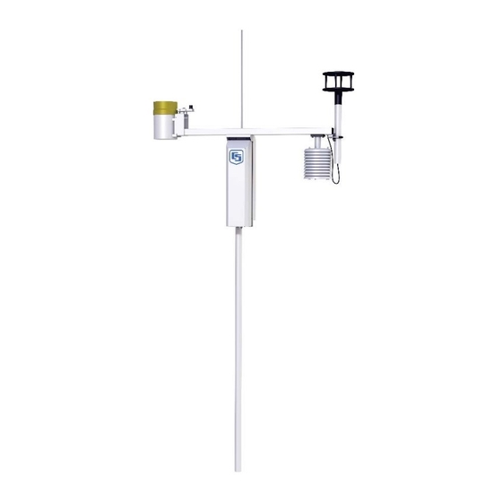
Campbell T107 Manuals
Manuals and User Guides for Campbell T107. We have
3
Campbell T107 manuals available for free PDF download: Instruction Manual, Product Manual
Campbell T107 Instruction Manual (106 pages)
Brand:
Campbell
| Category:
Weather Station
| Size: 5.09 MB
Table of Contents
Table of Contents
5
1 Preparation and Siting
9
Siting and Exposure
9
Wind Speed and Direction
9
Effect of Structure on Wind Flow
9
Temperature and Relative Humidity
10
Solar Radiation
10
Installation Tasks
10
Indoors
10
Cut Flap Packing Tape
11
Shipping Box Packaging
11
T107 with the Met One 034B-ETM Wind Sensor, Top Layer
12
T107, Bottom Layer
12
Outdoors
13
Tools Required
13
Tools for Pole Installation
13
Tools for Instrumentation and Maintenance
14
Supplies for Power and Communications Options
14
Determining True North for Wind Vane Orientation
15
Magnetic Declination for the Contiguous United States
15
Web Calculator
16
Declination Angles East of True North Are Subtracted from 0 to
16
Declination Angles West of True North Are Added to 0 to Get
16
2 Hardware Installation
18
ET Tower Installation with Currently-Available AC Power Option
18
Base Foundation
19
Supplied Components
19
Installation
19
ET Tower Base Installation
20
Cut-Away View Shows Anchor Bolt and Conduit Placement in Cement Pad
20
AC Power Installation
21
Tower/Pole
21
Supplied Components
21
Installation
21
Transparent View Shows Raising and Grounding the ET Tower
22
Tower Grounding
23
Supplied Components
23
Grounding Procedure
23
Close up of Ground Rod and 4 AWG Cable
23
Enclosure
24
Enclosure Installation
24
T107 Instrumentation Mounted on the ET Tower
24
Crossarm and Sensor Installation
25
Components
25
Crossarm Installation
25
Enclosure Spacing above Pole
25
T107 Sensor Arm Mounting
26
RH and Temperature Radiation Shield
27
Temperature/Relative Humidity Sensor with Yellow Protective Cap
27
Wind Sensor (Wind Sensor Option -MW)
28
Temperature/Relative Humidity Sensor Without Yellow Protective Cap
28
Wind and Rh/Temperature Sensor Installation
29
Gill Windsonic 2-D Ultrasonic Wind Sensor (Wind Sensor Option -GW)
30
Changing the Jumper
30
Screws that Secure the Electronics Cover
31
Attachment to Sensor Arm
32
Gill Windsonic Mounting Shaft
33
Rain Gage
34
Pyranometer
35
Sensor Connections
36
Connecting Sensor Cabling to Enclosure
37
Sensor Verification and Clock Set
38
Communication Peripherals
38
Direct Connect to T107 Station
38
Close-Up of the Terminals and 9-Pin Ports in the T107
39
Phone Modem
40
Internal Installation
40
External Installation
41
Short-Haul Modem
41
Internal Installation
42
Short-Haul Modem Mounting and Connection
42
External Installation
43
RF450 900 Mhz, 1 Watt Spread Spectrum Radio
44
Power Considerations
44
Short-Haul Modem Wiring Diagram
44
Default Configuration
45
Internal Installation
45
RF450 in T107 (Battery Not Shown)
46
External Installation
47
Loosely Wire Tie Antenna Cable
47
Loosely Drape Antenna Cable over Back of Enclosure
48
Slide Antenna Bracket U-Bolt Around Back of the Pole
49
Antenna Bracket Mounted to Pole
50
Yagi Antenna Mounted to Saddle Bracket
51
Wire Tie Antenna Cable to Yagi Antenna and to Pole
52
Base Radio Installation
53
Base RF450 Installation
54
Lightning Rod Installation
55
Grounding to Lightning Rod Clamp
56
Solar Panel Installation
57
Side View of Solar Panel Shows Tilt Angle
58
Battery Installation
59
Restraining Cables and Sealing/Desiccating Enclosure
60
Restraining Cables
60
Sealing and Desiccating the Enclosure
61
3 ET Software
62
4 Maintenance, Troubleshooting, and Schematics
63
Maintenance
63
Pole
63
Power Supply
63
Batteries
63
Solar Panel
63
Desiccant
64
Sensor Maintenance
64
Procedure for Removing RH Chip
66
CR1000M Module
66
Troubleshooting
67
No Response Using the CR1000KD Keypad
67
CR1000 Lithium Battery Specifications
67
No Response from Datalogger through SC32B, RAD Modem, or Phone Modem
68
NAN or INF Displayed in a Variable
68
Unreasonable Results Displayed in a Variable
69
NAN or INF Stored in a Data Table
69
Communication Problems When Using an RF450 Radio
69
RF450 Front Side View
69
Multi-Point Network LED Status
70
Gill Windsonic1-ET Diagnostic Diagnostic Codes
71
Schematics of Connectors
72
Sensor Schematics
72
Schematic of HMP60-ETS RH and Temperature Probe and Connector Temp/Rh
72
Gill Windsonic Diagnostic Codes
72
Schematic of 034B-LC Wind Speed and Direction Probe and
73
Schematic of Gill Windsonic1-ET Wind Sensor, Soil Temperature Sensor (107-LC or 108-LC), and Connector Temp/Sonic
73
Schematic of CS305-ET Solar Radiation Sensor and Connector Solar Radiation
74
Schematic of TE525-ET Rain Sensor and Connector Rain
75
Schematic of 107-LC or 108-LC Temperature Probe or CS616-LC Soil Volumetric Water Content Sensor and Connector Temp
76
Schematic of Connector SDI-12
76
Power Schematics
77
Communication Modems Schematics
77
T107 Maintenance Log
79
PS24 24 Ahr Power Supply and 10 X 12 Inch Enclosure
81
S24 Components
81
Environmental Enclosure with CH100, Power Cable, and Battery Bracket
81
Installation
84
Exploded Views
93
Enclosure
93
Crossarm
94
Program for T107 with 034B
95
Connector WS/WD
96
Program for T107 with Gill Windsonic
98
Step-Down Transformer Installation
103
ET Tower Installation with Step-Down Transformer
103
Advertisement
Campbell T107 Instruction Manual (116 pages)
Brand:
Campbell
| Category:
Weather Station
| Size: 14.54 MB
Table of Contents
Table of Contents
5
Preparation and Siting
5
1 Preparation and Siting
11
Siting and Exposure
11
Wind Speed and Direction
11
Temperature and Relative Humidity
12
Solar Radiation
12
Installation Tasks
12
Indoors
12
A. Cut Flap Packing Tape
13
T107 with the Met One 034B-ETM Wind Sensor, Top Layer
14
Outdoors
15
Tools Required
15
Tools for Pole Installation
15
Tools for Instrumentation and Maintenance
16
Supplies for Power and Communications Options
16
Determining True North for Wind Vane Orientation
17
Web Calculator
18
Added to 0 to Get True North
18
Subtracted from 0 to Get True North
18
2 Hardware Installation
21
Base Foundation
22
Supplied Components
22
Installation
22
Cement Pad
23
ET Tower Base Installation
23
AC Power Installation
24
Tower/Pole
24
Supplied Components
24
Installation
24
Transparent View Shows Raising and Grounding the et Tower
26
Tower Grounding
27
Grounding Procedure
27
Supplied Components
27
Enclosure
28
Enclosure Installation
28
Crossarm and Sensor Installation
29
Components
29
Crossarm Installation
29
T107 Sensor Arm Mounting
30
RH and Temperature Radiation Shield
31
Protective Cap
31
Temperature/Relative Humidity Sensor Without Yellow Protective Cap
32
Wind Sensor (Wind Sensor Option -MW)
32
Protective Cap
32
Wind and Rh/Temperature Sensor Installation
33
Gill Windsonic 2-D Ultrasonic Wind Sensor (Wind Sensor Option -GW)
34
Changing the Jumper
34
Screws that Secure the Electronics Cover
35
Attachment to Sensor Arm
36
Gill Windsonic Mounting Shaft
37
Rain Gage
38
Pyranometer
39
Sensor Connections
40
Connecting Sensor Cabling to Enclosure
41
Sensor Verification and Clock Set
42
Communication Peripherals
42
Direct Connect to T107 Station
42
Phone Modem
44
Internal Installation
44
External Installation
45
Short-Haul Modem
45
Internal Installation
46
External Installation
47
RF450 900 Mhz, 1 Watt Spread Spectrum Radio
48
Default Configuration
49
Power Considerations
49
Internal Installation
50
External Installation
51
Loosely Wire Tie Antenna Cable
52
Slide Antenna Bracket U-Bolt Around Back of the Pole
53
Antenna Bracket Mounted to Pole
54
Yagi Antenna Mounted to Saddle Bracket
55
Wire Tie Antenna Cable to Yagi Antenna and to Pole
56
Base Radio Installation
57
Base RF450 Installation
58
Lightning Rod Installation
59
Grounding to Lightning Rod Clamp
60
Solar Panel Installation
61
Side View of Solar Panel Shows Tilt Angle
62
Battery Installation
63
Restraining Cables and Sealing/Desiccating Enclosure
64
Restraining Cables
64
Sealing and Desiccating the Enclosure
65
Desiccant Installation
66
3 ET Software
67
4 Maintenance, Troubleshooting, and Schematics
69
Maintenance
69
Pole
69
Power Supply
69
Batteries
69
Solar Panel
69
Desiccant
69
Sensor Maintenance
70
Procedure for Removing RH Chip
72
CR1000M Module
73
Troubleshooting
74
No Response Using the CR1000KD Keypad
74
No Response from Datalogger through SC32B, RAD Modem, or Phone Modem
74
NAN or ±INF Displayed in a Variable
75
Unreasonable Results Displayed in a Variable
75
NAN or ±INF Stored in a Data Table
76
Communication Problems When Using an RF450 Radio
76
Gill Windsonic1-ET Diagnostic Diagnostic Codes
78
Schematics of Connectors
79
Sensor Schematics
80
Schematic of 034B-LC Wind Speed and Direction Probe and Connector WS/WD
81
Schematic of CS305-ET Solar Radiation Sensor and Connector Solar Radiation
82
Schematic of TE525-ET Rain Sensor and Connector Rain (Precip)
83
Schematic of Connector SDI-12
84
Power Schematics
85
Communication Modems Schematics
85
T107 Maintenance Log
87
Enclosure
88
PS24 Components
89
Installation
92
Exploded Views
101
Enclosure
101
Crossarm
102
Program for T107 with 034B
103
Program for T107 with Gill Windsonic
107
Step-Down Transformer Installation
113
Campbell T107 Product Manual (102 pages)
Brand:
Campbell
| Category:
Weather Station
| Size: 17.22 MB
Table of Contents
Table of Contents
5
1 Introduction
8
2 Precautions
9
3 Initial Inspection
10
4 Quickstart
13
User-Supplied Tools
13
Supplies for Power and Communications Options
15
5 Siting and Exposure
17
Wind Speed and Direction
17
Temperature and Relative Humidity
18
Solar Radiation
18
6 Installation
19
Base Foundation Installation
19
AC Power Installation Procedure
21
Pole Installation
23
Pole Grounding
25
Enclosure Installation
26
Crossarm Installation Procedure
27
Sensor Installation
28
RH and Temperature Radiation Shield Installation Procedure
29
Wind Sensor (Wind Sensor Option -MW)
31
Windsonic 2-D Ultrasonic Wind Sensor (Wind Sensor Option -GW)
33
Changing the Jumper
33
Windsonic Attachment to Crossarm
35
Rain Gage
37
Pyranometer
38
Sensor Connections
40
Sensor Verification and Clock Set
41
Communication Peripherals
42
Direct Connect to T107 Station
42
Phone Modem
43
Internal Installation of Phone Modem
44
External Installation of Phone Modem
45
Short-Haul Modem
45
Internal Installation of Short Haul Modem
45
External Installation of Short Haul Modem
47
Radio
48
Example Radio Configuration and Power Usage
49
Internal Installation of the Radio
49
External Installation of the Radio
51
Base Radio Installation
57
Lightning Rod Installation
58
Solar Panel Installation
60
Battery Installation
62
Restraining Cables
63
Sealing and Desiccating the Enclosure
64
T107 Software
65
7 Maintenance and Troubleshooting
67
Maintenance
67
Pole Maintenance
67
Power Supply Maintenance
67
Desiccant
67
Sensor Maintenance
68
Procedure for Removing RH Chip
71
Data Logger Module
71
Troubleshooting
72
No Response Using the CR1000KD Keypad
72
No Response from Data Logger When Using a Communication Peripheral
73
NAN, ±INF, or Unreasonable Results Displayed in a Variable or Stored in a Data Table
74
Windsonic1-ET Diagnostic Codes
74
8 Schematics of Connectors
76
Sensor Schematics
76
Power Schematics
80
Communication Modems Schematics
81
9 References
82
Appendix A. Determining True North and Wind Sensor Orientation
83
Online Magnetic Declination Calculator
85
Appendix B. T107 Maintenance Log
87
Appendix C. PS24 24 Ah Power Supply with 10 X 12 Inch Enclosure
90
PS24 Components
90
PS24 Installation
92
C.2 PS24 Installation
92
Advertisement
Advertisement
Related Products
Campbell TurfWeather
Campbell TLX106
Campbell TX312
Campbell TE525
Campbell TDR
Campbell TX320
Campbell TCAV
Campbell TB4
Campbell TX325
Campbell TX321
Campbell Categories
Measuring Instruments
Accessories
Modem
Weather Station
Recording Equipment
More Campbell Manuals
Login
Sign In
OR
Sign in with Facebook
Sign in with Google
Upload manual
Upload from disk
Upload from URL