Table of Contents
Advertisement
Quick Links
Download this manual
See also:
Operating Manual
Advertisement
Table of Contents

Related Manuals for Thermal Arc 161 S


Summary of Contents for Thermal Arc 161 S
- Page 1 161 S THERMAL ARC ® INVERTER ARC WELDER Art#: A-09901 Operating Manual Revision: AB Issue Date: July 14, 2011 Manual No.: 0-5183 Operating Features:...
- Page 2 YOU ARE IN GOOD COMPANY! The Brand of Choice for Contractors and Fabricators Worldwide. Thermal Arc is a Global Brand of Arc Welding Products for Thermadyne Industries Inc. We manufacture and supply to major welding industry sectors worldwide including; Manufacturing, Construction, Mining, Automotive, Aerospace, Engineering, Rural and DIY/Hobbyist.
- Page 3 Manufacturer assumes no liability for its use. Operating Manual Number 0-5183 for: Thermal Arc 161 S Power Source Arc Welder Part No. W1003604 Thermal Arc 161 S System with Stick Kit & Case Part No. W1003605 Published by: Thermadyne Europe...
-
Page 4: Table Of Contents
TABLE OF CONTENTS SECTION 1:SAFETY INSTRUCTIONS AND WARNINGS ..........1-1 1.01 Arc Welding Hazards ..................1-1 1.02 General Safety Information for Victor CS Regulator .......... 1-4 1.03 Principal Safety Standards ..................1.04 Symbol Chart ....................1-6 1.05 Declaration Of Conformity ................1-7 SECTION 2:INTRODUCTION ................ - Page 5 TABLE OF CONTENTS SECTION 4:OPERATION ..................4-1 4.01 Front Panel ..................... 4-1 4.02 Welding Current Control Explanation .............. 4-2 4.03 STICK (MMA) Electrode Polarity ..............4-2 4.04 Effects of Stick Welding Various Materials ............4-3 4.05 GTAW Electrode Polarity ................. 4-4 4.06 Guide for Selecting Filler Wire ................
- Page 6 Thermal Arc 161S Stick System Part Number W1003605 • Thermal Arc 161S power supply in toolbox • Electrode holder, 5m (16.4ft) • Work lead, 5m (16.4ft) • 4 GP 3.2mm (1/8") dia stick electrodes • Operating manual Art# A-09913...
-
Page 7: Section 1:Safety Instructions And Warnings
SAFETY INSTRUCTIONS THERMAL ARC 161 S SECTION 1: SAFETY INSTRUCTIONS AND WARNINGS WARNING PROTECT YOURSELF AND OTHERS FROM POSSIBLE SERIOUS INJURY OR DEATH. KEEP CHILDREN AWAY. PACEMAKER WEARERS KEEP AWAY UNTIL CONSULTING YOUR DOCTOR. DO NOT LOSE THESE INSTRUCTIONS. READ OPERATING/INSTRUCTION MANUAL BEFORE INSTALLING, OPERATING OR SERVICING THIS EQUIPMENT. -
Page 8: Safety Instructions
THERMAL ARC 161 S SAFETY INSTRUCTIONS WARNING WARNING WELDING can cause fire or explosion. FUMES AND GASES can be hazardous to your Sparks and spatter fly off from the welding arc. health. The flying sparks and hot metal, weld spatter, hot Welding produces fumes and gases. - Page 9 SAFETY INSTRUCTIONS THERMAL ARC 161 S possibly unknown paths and causing electric shock and fire hazards. 9. Do not use welder to thaw frozen pipes. WARNING 10. Remove stick electrode from holder or cut off welding wire at ENGINE EXHAUST GASES can kill.
-
Page 10: General Safety Information For Victor Cs Regulator
THERMAL ARC 161 S SAFETY INSTRUCTIONS Batteries contain acid and generate explosive gases. 1. Always wear a face shield when working on a battery. ABOUT PACEMAKERS: 2. Stop engine before disconnecting or connecting battery The above procedures are among those also normally cables. -
Page 11: Personal Protection
SAFETY INSTRUCTIONS THERMAL ARC 161 S Ventilation WARNING WARNING Cylinders are highly pressurized. Handle with care. Serious accidents can result from improper handling Ade quately ventilate welding, heating, and cutting or mis use of compressed gas cylinders DO NOT drop... -
Page 12: Symbol Chart
THERMAL ARC 161 S SAFETY INSTRUCTIONS 1.04 Symbol Chart Note that only some of these symbols will appear on your model. Wire Feed Function Single Phase Wire Feed Towards Workpiece With Three Phase Output Voltage Off. Three Phase Static Frequency Converter-... -
Page 13: Declaration Of Conformity
SAFETY INSTRUCTIONS THERMAL ARC 161 S 1.05 Declaration Of Conformity Manufacturer: Thermadyne Corporation Address: 82 Benning Street West Lebanon, New Hampshire 03784 The equipment described in this manual conforms to all applicable aspects and regulations of the ‘Low Voltage Directive’ (European Council Directive 73/23/EEC as amended by Council Directive 93/68/EEC) and to the National legislation for the enforcement of this Directive. - Page 14 THERMAL ARC 161 S SAFETY INSTRUCTIONS This page left blank intentionally. Safety Instructions Manual 0-5183...
-
Page 15: Section 2:Introduction
INTRODUCTION THERMAL ARC 161 S SECTION 2: INTRODUCTION 2.01 How to Use This Manual 2.04 Description This compact inverter welding machine has infinitely This Operating Manual usually applies to the part num- bers listed on page i. If none are underlined, they are adjustable welding current from 10 to 160 amps. -
Page 16: Specifications
The recommended time delay fuse or circuit breaker size is 32 amp for 110V and 32 amp for 230V. Thermal Arc continuously strives to produce the best product possible and therefore reserves the right to change, improve or revise the specifications or design of this or any product without prior notice. -
Page 17: Section 3:Installation
• In areas, not exposed to direct sunlight or rain. • Place at a distance of 300mm (12”) or more from walls or similar that could restrict natural air flow for cooling WARNING Thermal Arc advises that this equipment be electrically connected by a qualified electrician. 3.03 Electrical Input Connections WARNING ELECTRIC SHOCK can kill; SIGNIFICANT DC VOLTAGE is present after removal of input power. DO NOT TOUCH live electrical parts. - Page 18 THERMAL ARC 161 S INSTALLATION • Electrical Input Requirements Operate the welding power source from a single-phase 50/60 Hz, AC power supply. The input voltage must match one of the electrical input voltages shown on the input data label on the unit nameplate. Contact the local electric utility for information about the type of electrical service available, how proper connections should be made, and inspection required.
-
Page 19: Electromagnetic Compatibility
INSTALLATION THERMAL ARC 161 S 3.04 Electromagnetic Compatibility The size of the surrounding area to be considered will depend on the structure of the building and other activities that are taking place. The surrounding area may extend beyond the boundaries of the premises. -
Page 20: Setup For Welding
THERMAL ARC 161 S INSTALLATION 3.05 Setup for Welding 5. Earthing of the Work Piece Where the work piece is not bonded to earth for NOTE electrical safety, nor connected to earth because Conventional operating procedures apply of its size and position, e.g. ship’s hull or building when using the Welding Power Source, i.e. -
Page 21: Stick (Mma) Setup
INSTALLATION THERMAL ARC 161 S 3.06 STICK (MMA) Setup Set Welding Current as specified by the Set Process Selection Electrode Manufacturer. Switch to STICK (MMA) Negative Output Positive Output Terminal Terminal (Dinse™ 50) (Dinse™ 50) Art #: A-09914 Figure 3-2: Setup for STICK (MMA) Welding STICK (MMA) Mode Sequence of Operation 3. -
Page 22: Lift Tig (Gtaw) Setup
THERMAL ARC 161 S INSTALLATION 3.07 LIFT TIG (GTAW) Setup Set Process Selection Switch to LIFT TIG (GTAW). Set Welding Current as specified by the Electrode Manufacturer. Negative Output Terminal (Dinse™ 50) Secure the gas cylinder in an Positive Output... - Page 23 INSTALLATION THERMAL ARC 161 S 9. Set the “Process Selection Switch” to LIFT TIG 10. Set the weld current control knob to the desired amperage. 11. The tungsten must be ground to a blunt point in order to achieve optimum welding results. It is critical to grind the tungsten electrode in the direction the grinding wheel is turning.
- Page 24 THERMAL ARC 161 S INSTALLATION This page is left blank intentionally. Installation Manual 0-5183...
-
Page 25: Section 4:Operation
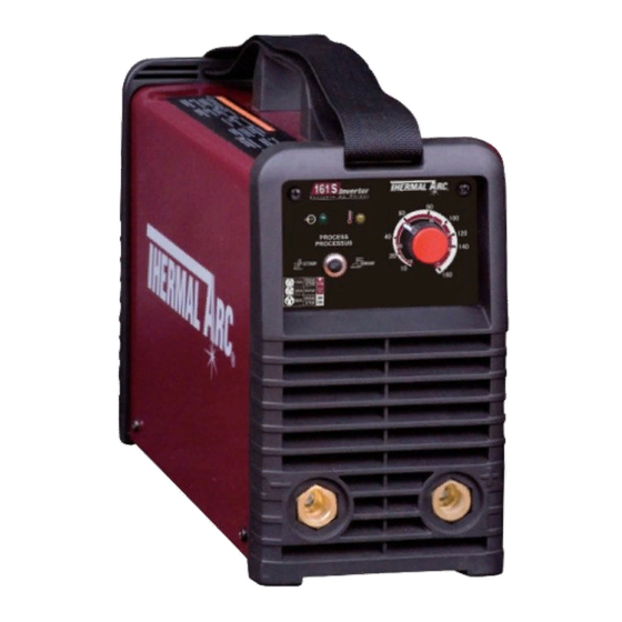
This switch controls the Mains Supply Voltage to the voltage is present. Power Source. FAULT PROCESS (A) Process Selection Switch STICK 32A OUTLET 32A OUTLET 110V TIG/STICK 16A OUTLET 230V Art#: A-09902 Figure 4-1: Thermal Arc 161 S Controls Manual 0-5183 Operation... -
Page 26: Welding Current Control Explanation
THERMAL ARC 161 S OPERATION 4.02 Welding Current Control LIFT TIG Mode: A 32 Amp outlet is capable of supplying enough input power for all LIFT TIG Explanation output weld current values. Nuisance tripping should not occur on a 32 Amp out- 32 Amp Outlet let. -
Page 27: Effects Of Stick Welding Various Materials
OPERATION THERMAL ARC 161 S malleable, due to the porosity caused by gas held in 4.04 Effects of Stick Welding Various this type of iron. Materials Copper and Alloys High Tensile and Alloy Steels The most important factor is the high rate of heat... -
Page 28: Gtaw Electrode Polarity
THERMAL ARC 161 S OPERATION 4.05 GTAW Electrode Polarity Connect the TIG torch to the "-" Negative Output Terminal and the work lead to the "+" Positive Output Terminal for direct current straight polarity. Direct current straight polarity is the most widely used polarity for DC TIG welding. It allows limited wear of the electrode since 70% of the heat is concentrated at the work piece. -
Page 29: Tig Welding Parameters For Steel
OPERATION THERMAL ARC 161 S 4.10 TIG Welding Parameters for Steel DC Current Stainless Base Metal Electrode Filler Rod Argon Gas Flow Mild Steel Steel Thickness Diameter Diameter Rate Joint / Type 35-45 20-30 Butt/Corner 1.0mm 1.6mm 1.0mm 5 LPM (.040") -
Page 30: Welding Position
THERMAL ARC 161 S OPERATION 4.12 Welding Position The electrodes dealt with in this publication can be used in most positions, i.e. they are suitable for welding in flat, horizontal, vertical and overhead positions. Numerous applications call for welds to be made in positions intermediate between these. -
Page 31: Joint Preparations
OPERATION THERMAL ARC 161 S 4.13 Joint Preparations In many cases, it will be possible to weld steel sections without any special preparation. For heavier sections and for repair work on castings, etc., it will be necessary to cut or grind an angle between the pieces being joined to ensure proper penetration of the weld metal and to produce sound joints. -
Page 32: Arc Welding Technique
THERMAL ARC 161 S OPERATION 4.14 Arc Welding Technique Another difficulty you may meet is the tendency, after the arc is struck, to withdraw the electrode so far that A Word to Beginners the arc is broken again. A little practice will soon remedy both of these faults. -
Page 33: Making Welded Joints
OPERATION THERMAL ARC 161 S 4.19 Making Welded Joints Heavy plate will require several runs to complete the joint. After completing the first run, chip the slag out Having attained some skill in the handling of an elec- and clean the weld with a wire brush. It is important... - Page 34 THERMAL ARC 161 S OPERATION Art # A-07702 Art # A-07700 Figure 4-16: Multi-runs in HV fillet weld C. Vertical Welds Figure 4-18: Multi run vertical fillet weld 1. Vertical Up Tack weld a three feet length of angle iron to your work bench in an upright position.
-
Page 35: Distortion
OPERATION THERMAL ARC 161 S that the weld deposit is rather convex, due to B. Expansion and Contraction of Parent Metal in the the effect of gravity before the metal freezes. Fusion Zone: While welding is proceeding, a relatively small volume... -
Page 36: Overcoming Distortion Effects
THERMAL ARC 161 S OPERATION 4.22 Overcoming Distortion Effects Art # A-07708 There are several methods of minimizing distortion Preheat Preheat effects. Weld A. Peening This is done by hammering the weld while it is still hot. Dotted lines show effect if no preheat is used The weld metal is flattened slightly and because of this the tensile stresses are reduced a little. - Page 37 OPERATION THERMAL ARC 161 S Art # A-07712 Figure 4-28: Chain intermittent welding Art # A-07713_AB Figure 4-29: Staggered intermittent welding Manual 0-5183 4-13 4-13 Operation...
- Page 38 THERMAL ARC 161 S OPERATION This Page Intentionally Blank. Operation 4-14 4-14 Manual 0-5183...
-
Page 39: Section 5:Service
SERVICE THERMAL ARC 161 S SECTION 5: SERVICE 5.01 Maintenance and Inspection To clean the unit, open the enclosure and use a vacuum cleaner to remove any accumulated dirt and dust. The The only routine maintenance required for the power unit should also be wiped clean, if necessary;... -
Page 40: Stick (Mma) Welding Problems
THERMAL ARC 161 S SERVICE 5.02 STICK (MMA) Welding Problems Description Possible Cause Remedy 1. Gas pockets or voids in weld metal Electrodes are damp. A. Dry electrodes before use. (Porosity). Welding current is too high. B. Reduce welding current. -
Page 41: Tig Welding Problems
SERVICE THERMAL ARC 161 S 5.03 TIG Welding Problems Weld quality is dependent on the selection of the correct consumables, maintenance of equipment and proper welding technique. Description Possible Cause Remedy 1. Excessive bead build-up or poor Welding current is too low... -
Page 42: Power Source Problems
There are extremely dangerous voltages and power levels present inside this product. Do not attempt to repair unless you are an Accredited Thermal Arc Service Agent and you have had training in power measurements and troubleshooting techniques. If major complex subassemblies are faulty, then the Welding Power Source must be returned to an Accredited Thermal Arc Service Agent for repair. -
Page 43: Appendix 1: Options And Accessories
APPENDIX THERMAL ARC 161 S APPENDIX 1: OPTIONS AND ACCESSORIES Description Part Number USA Graphics Auto-Darkening welding helmet, spare cover lens and operating W4011700 manual Canadian Graphics Auto-Darkening welding helmet, spare cover lens and operating W4011800 manual Claret Colour Auto-Darkening welding helmet, spare cover lens and operating manual... -
Page 44: Appendix 2: Replacement Parts
There are extremely dangerous voltages and power levels present inside this product. Do not attempt to repair unless you are an Accredited Thermal Arc Service Agent and you have had training in power measurements and troubleshooting techniques. If major complex subassemblies are faulty, then the Welding Power Source must be returned to an Accredited Thermal Arc Service Agent for repair. - Page 45 APPENDIX THERMAL ARC 161 S Art # A-09931_AB Manual 0-5183 Appendix...
-
Page 46: Appendix 3: System Schematic
THERMAL ARC 161S APPENDIX APPENDIX 3: SYSTEM SCHEMATIC J9-1 J1-2 J9-2 J1-1 -24V J2-1 J3-1 J2-2 J3-2 +15V J2-3 J3-3 IGBT Driver A J2-4 J3-4 IGBT Driver B J2-5 J3-5 J2-6 J3-6 Over Current Signal J2-7 J3-7 Over Current Signal... -
Page 47: Limited Warranty & Warranty Schedule
LIMITED WARRANTY & WARRANTY SCHEDULE In accordance with the warranty periods stated below, Thermadyne guarantees the proposed product to be free from defects in material or workmanship when operated in accordance with the written instructions as defined in this operating manual. Thermadyne welding products are manufactured for use by commercial and industrial users and trained personnel with experience in the use and maintenance of electrical welding and cutting equipment. - Page 48 Customer Care UK: +44 (0)1257 261 755 / Fax: +44 (0)1257 224 800 Customer Care Italy +39 02 36546801 / Fax: +39 02 36546480 www.thermadyne.com A Global Cutting & Welding Market Leader ™ W O R L D H E A D Q U A R T E R S : 1 6 0 5 2 S w i n g l e y R i d g e R o a d , S u i t e 3 0 0 •...
Need help?
Do you have a question about the 161 S and is the answer not in the manual?
Questions and answers