Table of Contents
Advertisement
Quick Links
VICTOR COMPANY OF JAPAN, LIMITED
VIDEO DIVISION
SPECIFICATIONS
GENERAL
Power requirement
Power consumption
Power on
Power off
Temperature
Operating
Storage
Operating position
Dimensions (WxHxD)
Weight
Format
Maximum recording time
(SP)
(LP)
(EP)
VIDEO/AUDIO
Signal system
Recording system
Signal-to-noise ratio
Horizontal resolution
(SP/LP)
(EP)
Frequency range
Input/Output
S40894
Printed in Japan
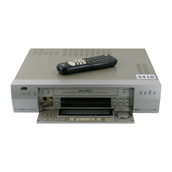
SERVICE MANUAL
VIDEO CASSETTE RECORDER
HR-S9700EK/EU
(The specifications shown pertain specifically to the model HR-S9700EU)
TUNER/TIMER
: AC 220 V – 240 V` , 50 Hz/60 Hz
TV channel storage capacity : 99 positions (+AUX position)
Tuning system
: 25 W
Channel coverage
: 5.2 W
: 5°C to 40°C
: –20°C to 60°C
Aerial output
: Horizontal only
Memory backup time
: 437 mm x 106 mm x 352 mm
: 5.1 kg
ACCESSORIES
: S-VHS/VHS PAL standard
Provided accessories
: 240 min. with E-240 video cassette
: 480 min. with E-240 video cassette
: 720 min. with E-240 video cassette
: PAL-type colour signal and CCIR monochrome
signal, 625 lines 50 fields
Specifications shown are for SP mode unless otherwise specified.
: DA4 (Double Azimuth) head helical scan system
E.& O.E. Design and specifications subject to change without notice.
: 45 dB
: 250 lines (VHS)
400 lines (S-VHS)
: 220 lines (VHS)
350 lines (S-VHS)
: 70 Hz to 10,000 Hz (Normal audio)
20 Hz to 20,000 Hz (Hi-Fi audio)
: 21-pin SCART connectors:
IN/OUT x 1, IN/DECODER x 1
RCA connectors:
VIDEO IN x 1, AUDIO IN x 1, AUDIO OUT x 1
S-Video connectors:
IN x 1, OUT x 1
This service manual is printed on 100% recycled paper.
COPYRIGHT © 2000 VICTOR COMPANY OF JAPAN, LTD.
: Frequency synthesized tuner
: VHF 47 MHz – 89 MHz/
104 MHz – 300 MHz/
302 MHz – 470 MHz
UHF 470 MHz – 862 MHz
: UHF channels 22 – 69 (Adjustable)
: Approx. 60 min.
: RF cable,
S-Video cable,
Satellite Controller RM-SD1,
Infrared remote control unit,
"R6" battery x 2,
S-VHS ET labels
No. 82822
August 2000
Advertisement
Table of Contents

Related Manuals for JVC HR-S9700EK


Summary of Contents for JVC HR-S9700EK
- Page 1 SERVICE MANUAL VIDEO CASSETTE RECORDER HR-S9700EK/EU SPECIFICATIONS (The specifications shown pertain specifically to the model HR-S9700EU) GENERAL TUNER/TIMER Power requirement : AC 220 V – 240 V` , 50 Hz/60 Hz TV channel storage capacity : 99 positions (+AUX position)
-
Page 2: Table Of Contents
3. ELECTRICAL ADJUSTMENT 3.1 PRECAUTION ..................3-1 3.1.1 Required test equipments .............. 3-1 3.1.2 Required adjustment tools ............... 3-1 The following table lists the differing points between Models (HR-S9700EK AND HR-S9700EU) in this series. HR-S9700EK HR-S9700EU VIDEO SYSTEM PAL/NTSC PB ON PAL TV... -
Page 3: Important Safety Precautions
Important Safety Precautions Prior to shipment from the factory, JVC products are strictly inspected to conform with the recognized product safety and electrical codes of the countries in which they are to be sold. However, in order to maintain such compliance, it is equally important to implement the following precautions when a set is being serviced. - Page 4 • Safety Check after Servicing Examine the area surrounding the repaired location for damage or deterioration. Observe that screws, parts and wires have been returned to original positions, Afterwards, perform the following tests and confirm the specified values in order to verify compliance with safety standards.
-
Page 5: Disassembly
SECTION 1 DISASSEMBLY 1.3 DISASSEMBLY/ASSEMBLY METHOD 1.1 DISASSEMBLY FLOW CHART Step/ Fig. This flowchart lists the disassembling steps for the cabinet Part Name Point Note Loc No. parts and P.C. boards in order to gain access to item(s) Top cover D1 4(S1a),(S1b) to be serviced. - Page 6 Procedures for Lowering the Cassette holder assembly As the mechanism of this unit is integrated with the Housing assembly, the holder must be lowered and the two screws un- (L2c) screwed when removing the Mechanism assembly. (L2b) (L2a) (L2d) (L2b) (L2a) Fig.
- Page 7 A/C head base Note: When installing the Mechanism assembly, secure the screws (S5a) in the order of a , b . Shaft Membrane door assembly Foil side <Note 3a> (S5b) <Note 5b> (S5a) <Note 5a> (S5c) (S3b) Damper assembly Q3003 End sensor (L5) <Note 5a>...
-
Page 8: Service Position
(3) Take out 2 screws A , 1 screw B and 1 screw C as shown in Fig. 1-4-1. (4) Remove the flat wires from CN3011, CN901 and CN902 (S7a) on the Main board assembly. (5) Take out 2 screws D , 1 screw E and 1 screw F as shown in Fig. -
Page 9: Precautions For Cassette Loading In The "Service Position
(9) Connect the power cord to the wall socket, and lift the Notes: cassette holder. • When performing diagnostics of the tape playback or the recording condition in the "SERVICE POSITION", (Before turning on the power make sure that there is noth- ing which may produce a short circuit, such as faulty sol- enter the desired mode before turning the set upside dering.) -
Page 10: Emergency Display Function
1.6.1 Displaying the emergency information 1.6 EMERGENCY DISPLAY FUNCTION (1) Transmit the code “59” from the Jig RCU. This unit has a function for storing the history of the past two The FDP shows the emergency content in the form of emergencies (EMG) and displaying them on each FDP. -
Page 11: Emergency Content Description
1.6.3 Emergency content description Note: Emergency contents “E08/E09” are for the model with Dynamic Drum (DD). CONTENT CAUSE E01: Loading EMG When the mechanism mode cannot be changed to an- 1 The mechanism is locked in the middle of mode transition. other mode even when the loading motor has rotated 2 The mechanism is locked at the loading end due to the encoder position for more than 4 seconds in the loading direction, [E:01]... -
Page 12: Emergency Detail Information 1
1.6.4 Emergency detail information 1 : Mechanism Operation Mode [Table of MN] The status (electrical operation mode) of the VCR and the sta- tus (mechanism operation mode/sensor information) of the Display Mechanism Operation Mode Command standby (Status without executing command) mechanism in the latest emergency can be confirmed based on POWER OFF by EMG occurrence the figure in EMG detail information 1 . -
Page 13: Emergency Detail Information 2
1.6.5 Emergency detail information 2 : Mechanism Sensor Information 3 – [Common table of MN and HD] The type of the cassette tape and the cassette tape winding po- sition can be confirmed based on the figure in EMG detail infor- Mechanism Sensor Information Display S-VHS SW... -
Page 14: Servicing The Video Navigation Function
1.7 SERVICING THE VIDEO NAVIGATION FUNCTION (1) Turn [OFF] the power of the 2 units (slave and master) The video navigation function is to record data to the built-in VCR and set it without a cassette tape. FLASH memory of the VCR. At the same time a reference number is wrote on the cassette tape for control purposes. -
Page 15: Erasing The Video Navigation Data (Initialization)
1.7.2 Erasing the video navigation data (Initialization) This is the service mode to erase all the video navigation Fig. 1-7-2b CH 1 data inside the FLASH memory. When a unit is replaced or after an operations check, erase the data which is not re- quired while observing the TV screen. -
Page 16: Mechanism Adjustment
SECTION 2 MECHANISM ADJUSTMENT 2.1 BEFORE STARTING REPAIR AND ADJUSTMENT 2.1.1 Precautions (1) Unplug the power cable of the main unit before using your Loading motor soldering iron. (2) Take care not to cause any damage to the conductor wires when plugging and unplugging the connectors. (3) Do not randomly handle the parts without identifying where the trouble is. -
Page 17: Jigs And Tools Required For Adjustment
2. In case of mechanical failure 2.1.4 Jigs and Tools Required for Adjustment If you cannot remove the cassette tape which is loaded be- Roller driver A/C head positioning tool Torque gauge cause of any mechanical failure, manually remove it by tak- PTU94002 PTU94010 PUJ48075-2... -
Page 18: Maintenance And Inspection
2.1.5 Maintenance and Inspection 1. Location of major mechanical parts In this chapter, the two mechanism speeds are described by comparing the speeds of the standard type and the high-speed FF/REW type. It is possible to distinguish between these two types of mechanism by the diameters of their capstan pulleys. The capstan pulley diameter for the standard type is approx. - Page 19 4. Suggested servicing schedule for main components The following table indicates the suggested period for such Guide rail Roller cam assembly service measures as cleaning,lubrication and replacement. In practice, the indicated periods will vary widely according to environmental and usage conditions.However, the indi- cated components should be inspected when a set is brought for service and the maintenance work performed if neces- sary.
- Page 20 Symbols and numbers R4 R1 T9 T12 T11 B15 B12 B14 B13 B17 B21 B7 B8 B5 B4 B11 T14 T15 T13 T22 T24 T18 B19 Removal parts (Reference items) Replacement parts 2.2.3 Guide rail 2.2.3 Roller cam assembly 2.2.3 Cassette housing bracket 2.2.3 Opener guide 2.2.3 Door opener 2.2.3 Relay gear...
-
Page 21: Replacement Of Major Parts
2.2 REPLACEMENT OF MAJOR PARTS 2.2.3 Cassette Holder Assembly 1. How to remove 2.2.1 Before Starting Disassembling (Phase matching (1) Remove the guide rail and roller cam assembly. (See between mechanical parts) Fig.2-2-3a.) The mechanism of this unit is closely linked with the rotary (3 lugs on the guide rail and one lug on the roller cam encoder and system controller circuits. - Page 22 (5) While holding the left side of the cassette holder, lift the 2. How to install (Phase matching) cassette holder assembly so that the three legs on the (1) Insert the section A of the drive arm into the section B left side are all released.
-
Page 23: Pinch Roller Arm Assembly
2.2.6 Audio Control Head Notches Guide hole Notch 1. How to remove Relay gear (1) Remove the two screws (A) and remove the audio con- trol head together with the head base. (2) When replacing only the audio control head, remove the three screws (B) while controlling the compression spring. -
Page 24: Capstan Motor
2. How to install (Centering the mounting position) Loading motor board assembly When the capstan motor has once been removed and then reinstalled out of the initial correct position in the rotational Loading motor direction, the capstan motor current may be unstable during Lugs Motor guide operation in high or low temperatures. -
Page 25: Rotary Encoder
2.2.10 Rotary Encoder 2.2.12 Change Lever Assembly, Direct Gear, Clutch Gear and Coupling Gear 1. How to remove (1) Remove the screw (A) and remove the rotary encoder 1. How to remove by pulling it up. (See Fig. 2-2-10a.) (1) Release the two lugs of the rotary encoder guide in the arrow-indicated direction and remove the change lever assembly. -
Page 26: Link Lever
2.2.13 Link Lever 2.2.14 Cassette Gear, Control Cam and Worm Gear 1. How to remove 1. How to remove (1) Remove the two slit washers. (1) Remove the control cam by lifting it. (2) Remove the link lever by lifting it from the shaft retained (2) Open the two lugs of the cassette gear outward and pull by the slit washers. -
Page 27: Loading Arm Gear (Supply Or Take-Up Side) And Loading Arm Gear Shaft
(3) Install the control plate so that the section A of the load- (3) Turn the loading arm gear (take-up side) clockwise so ing arm gear shaft fits into the hole (A) of the control plate, that the notch of the loading arm gear (take-up side) is the section B of the control plate guide into the hole (B), in alignment with the projection of the loading arm gear and the control plate comes under the section C of the... -
Page 28: Take-Up Lever, Take-Up Head And Control Plate Guide
2.2.17 Take-up Lever, Take-up Head and Control Plate Guide (1) Remove the spring of the take-up lever from the main deck. Spring (2) Remove the lug (A) of the take-up lever from the main Sub brake assembly deck and pull out the take-up lever and the take-up head Lug(A) (take-up side) together. -
Page 29: Tension Brake Assembly, Reel Disk (Supply Side) And Tension Arm Assembly
2.2.21 Tension Brake Assembly, Reel Disk (supply side) 2.2.23 Stator Assembly and Tension Arm Assembly (1) Remove the flat cable. 1. How to remove (2) Remove the two screws (A). (1) Remove the three lugs of the tension brake assembly (3) Remove the stator assembly by lifting in the arrow-indi- from the main deck and pull them off. -
Page 30: Upper Drum Assembly
2.2.25 Upper Drum Assembly 1. How to remove (1) Remove the stator assembly and rotor assembly. (2) Loosen the screw of the collar assembly using a 1.5 mm hexagonal wrench and remove the collar assembly. Also remove the brush, spring and cap at one time. Lower drum assembly (3) Remove the upper drum assembly and remove the washer using tweezers. -
Page 31: Compatibility Adjustment
2.3 COMPATIBILITY ADJUSTMENT (6) Make sure that the V.PB FM waveform varies in parallel and linearly with the tracking operation again. When re- Notes: quired, perform fine-adjustment of the guide roller of the • Although compatibility adjustment is very important, pole base assembly (supply or take-up side). -
Page 32: Checking/Adjustment Of The Height And Tilt Of The Audio Control Head
(3) Press the channel buttons (+, –) simultaneously to enter the manual tracking mode. This also brings tracking to the center (centre). (4) Adjust the AUDIO OUT waveform and Control pulse waveform by turning the screws (1), (2) and (3) little by little until both waveforms reach maximum. -
Page 33: Checking/Adjustment Of The Standard Tracking Preset
[Perform adjustment steps (7) to (10) only for 2 Head (1) Play back the alignment tape (A). models equipped with LP mode.] (2) Apply the external trigger signal to D.FF (E), to observe the V.PB FM waveform at the measuring point (D). (7) Then play back the alignment tape (A2). - Page 34 Mechanism Timing Chart EJECT CASS- Mechanism mode CASS-INS FF/REW STOP SLOW/STILL PLAY Control plate mark HIGH C CH HIGH Rotary encoder B CH HIGH A CH Control cam angle 264. 318. 412. Rotary encoder 114. 150. 167. 178. 207. 218. 240.
-
Page 35: Electrical Adjustment
SECTION 3 ELECTRICAL ADJUSTMENT 3.1 PRECAUTION Jig RCU The following adjustment procedures are not only necessary [Data transmitting method] Depress the “ ” ( 3 ) button after replacement of consumable mechanical parts or board after the data code is set. assemblies, but are also provided as references to be re- ferred to when servicing the electrical circuitry. -
Page 36: Servo Circuit
(1) Record the signal (A2) in the mode (B1), and play back the recorded signal. (2) Press the channel buttons (+, –) simultaneously to enter the manual tracking mode. This also brings tracking to the center (centre). (3) Set the VCR to the FWD slow (+1/6×) mode. (4) Transmit the code (F) from the Jig RCU to adjust so that Fig. -
Page 37: Video Circuit
3.3 VIDEO CIRCUIT (5) Release the EVR mode of the VCR by transmitting the code (F1) from the Jig RCU again. (When the EVR mode 3.3.1 D/A level is released, the adjusted data is memorized.) • Signal (A1) Ext. S-input / Ext. input •... -
Page 38: Rec Color (Colour) Level
3.3.4 REC color (colour) level • Signal (A1) Alignment tape(S-VHS, SP/LP, Color(colour) bar) [MH-2H] Specified • value (G) (A2) Ext. input • (A3) Color (colour) bar signal [PAL] • Mode (B1) S-VHS SP • (B2) S-VHS LP V. rate • Equipment Oscilloscope Fig. -
Page 39: Auto Picture Initial Setting
3.3.6 AUTO PICTURE initial setting • Signal (A1) Ext. input • (A2) Video: Optional Specified Specified value (G1) value (G2) • (A3) VHS tape • EE ¥ Auto adjust (SP/LP REC ¥ PB) Mode V. rate • Adjustment part Jig RCU : Code “58” Fig. -
Page 40: Charts And Diagrams
SECTION 4 CHARTS AND DIAGRAMS 4) Indication on schematic diagram NOTES OF SCHEMATIC DIAGRAM Voltage Indications for REC and PB mode on the sche- Safety precautions matic diagram are as shown below. The Components identified by the symbol critical for safety. For continued safety, replace safety critical components only with manufacturer's recom- REC mode mended parts. -
Page 41: Circuit Board Notes
6. Signal path Symbols CIRCUIT BOARD NOTES The arrows indicate the signal path as follows. 1. Foil and Component sides 1) Foil side (B side) : Playback signal path Parts on the foil side seen from foil face (pattern face) are indicated. -
Page 42: Board Interconnections
BOARD INTERCONNECTIONS OPEN OPEN OPEN (Page 4-17) J901 AV1 IN/OUT (Page 4-23) (Page 4-19) J912 J913 J923 J924 J925 J926 (Page 4-25) J903 S-OUT AUDIO OUT JLIP LANC SAT.CTL R.PAUSE (Page 4-27) J902 AV2 IN/OUT OPEN (VIDEO/AUDIO Page 4-5) (VSC Page 4-7) (SYSCON Page 4-9) -
Page 43: Video/Audio And Audio Erase Schematic Diagrams
TO SYSCON AUDIO ERASE WF18 TO CNR CN802 SECAM DET/KILLER OUT OPEN TO CNR CN801 p10273001a rev0.1 : Used : Not used Note : For the waveforms in this schematic diagram , refer to page 4-41. C2206 HR-J870EK/EU HR-S9700EK/EU 4-16... -
Page 44: Vsc Schematic Diagram
VSC SCHEMATIC DIAGRAM The Parts Number , value and rated voltage etc. in the Schematic Diagram are for references only. Note : When replacing the parts , refer to the Parts List. TO VIDEO/AUDIO Note : For the waveforms in this schematic diagram , refer to page 4-41. p30072001a rev0... -
Page 45: System Control Schematic Diagram
SYSTEM CONTROL SCHEMATIC DIAGRAM Note : The Parts Number , value and rated voltage etc. in the Schematic Diagram are for references only. When replacing the parts , refer to the Parts List. ( SYSCON ) (NC) TO VIDEO/AUDIO (NC) TO VIDEO/AUDIO TO SW.REG (NC) -
Page 46: Switching Regulator Schematic Diagram
SWITCHING REGULATOR SCHEMATIC DIAGRAM Note : The Parts Number , value and rated voltage etc. in the Schematic Diagram are for references only. When replacing the parts , refer to the Parts List. TO SYSCON TO CONNECTION TO VIDEO/AUDIO,SYSCON TUNER,CONNECTION TO SYSCON TO SYSCON TO SYSCON... -
Page 47: Tuner Schematic Diagram
TUNER SCHEMATIC DIAGRAM The Parts Number , value and rated voltage etc. in the Schematic Diagram are for references only. Note : When replacing the parts , refer to the Parts List. : Used : Not used TO SW.REG TO SYSCON SHORT TO VIDEO/AUDIO TO DEMOD... -
Page 48: Connection Schematic Diagram
CONNECTION SCHEMATIC DIAGRAM Note : The Parts Number , value and rated voltage etc. in the Schematic Diagram are for references only. When replacing the parts , refer to the Parts List. TO SW/DISPLAY CN7192 TO VIDEO/AUDIO OPEN TO SW/DISPLAY CN7191 FRONT VIDEO TO SW.REG... -
Page 49: Digital/2M Schematic Diagram
3D DIGITAL/2M SCHEMATIC DIAGRAM The Parts Number , value and rated voltage etc. in the Schematic Diagram are for references only. Note : When replacing the parts , refer to the Parts List. 3D DIGITAL/2M TO CONNECTION CN501 I2C DATA A/V I2C CLK A/V B1412 p10276001a rev0.1... -
Page 50: Terminal Schematic Diagram
TERMINAL SCHEMATIC DIAGRAM The Parts Number , value and rated voltage etc. in the Schematic Diagram are for references only. Note : When replacing the parts , refer to the Parts List. OPEN OPEN TO NAVI CN3402 TO CONNECTION CN907 TO CONNECTION CN904 SAT CTL... -
Page 51: Demodulator Schematic Diagram
4.10 DEMODULATOR SCHEMATIC DIAGRAM The Parts Number , value and rated voltage etc. in the Schematic Diagram are for references only. Note : When replacing the parts , refer to the Parts List. : Used : Not used TO TUNER CN6701 p20162001a rev2 4-21... -
Page 52: S-Sub Schematic Diagram
4.11 S-SUB SCHEMATIC DIAGRAM The Parts Number , value and rated voltage etc. in the Schematic Diagram are for references only. Note : When replacing the parts , refer to the Parts List. TO CONNECTION CN502 I2C DATA A/V I2C CLK A/V OPEN WF10 WF11... -
Page 53: Navigation Schematic Diagram [Lpb10108-001*]
4.12 NAVIGATION SCHEMATIC DIAGRAM [LPB10108-001*] There are currently two types of Navigation boards in used , these are the LPB10108-001* and the LPB10108-002*. Note : The Parts Number , value and rated voltage etc. in the Schematic Diagram are for references only. These two boards have different Schematic Diagrams and Parts Lists. -
Page 54: Navigation Schematic Diagram [Lpb10108-002*]
4.13 NAVIGATION SCHEMATIC DIAGRAM [LPB10108-002*] There are currently two types of Navigation boards in used , these are the LPB10108-001* and the LPB10108-002*. The Parts Number , value and rated voltage etc. in the Schematic Diagram are for references only. Note : These two boards have different Schematic Diagrams and Parts Lists. -
Page 55: Sw/Display And Rec Safety Schematic Diagrams
4.14 SW/DISPLAY AND REC SAFETY SCHEMATIC DIAGRAMS Note : The Parts Number , value and rated voltage etc. in the Schematic Diagram are for references only. When replacing the parts , refer to the Parts List. OPEN TO CONNECTION CN901 TO CONNECTION CN902 OPEN... -
Page 56: Digital/2M And S-Sub Circuit Boards
4.15 3D DIGITAL/2M AND S-SUB CIRCUIT BOARDS 4.16 TERMINAL CIRCUIT BOARD 05 3D DIGITAL/2M 06 TERMINAL COMPONENT PARTS LOCATION GUIDE LPB10105-001B LPB10100-001B 3D DIGITAL/2M COMPONENT PARTS LOCATION GUIDE COMPONENT PARTS LOCATION GUIDE TERMINAL TERMINAL REF.NO. LOCATION REF.NO. LOCATION REF.NO. LOCATION REF.NO. -
Page 57: Main, A/C Head, Audio Erase And Loading Motor Circuit Boards
4.17 MAIN , A/C HEAD , AUDIO ERASE AND LOADING MOTOR CIRCUIT BOARDS DANGEROUS VOLTAGE 03 MAIN LPB10106-001D 12 A/C HEAD LPB10010-001A 46 AUDIO ERASE LPB10106-001D 55 LOADING MOTOR LPB10010-001A 4-33 4-34... -
Page 58: Navigation Circuit Board
COMPONENT PARTS LOCATION GUIDE MAIN 4.18 NAVIGATION CIRCUIT BOARD REF.NO. LOCATION REF.NO. LOCATION REF.NO. LOCATION REF.NO. LOCATION REF.NO. LOCATION REF.NO. LOCATION REF.NO. LOCATION REF.NO. LOCATION REF.NO. LOCATION CAPACITOR C2001 C3041 CN3001 L2001 R2107 R3085 R5322 19 NAVIGATION C2002 C3042 CN3002 L2251 R2108 R3086... -
Page 59: Demodulator, Sw/Display And Rec Safety Circuit Boards
DEMODULATOR , SW/DISPLAY AND REC SAFETY CIRCUIT BOARDS 4.19 14 DEMODULATOR COMPONENT PARTS LOCATION GUIDE DEMODULATOR LPB10094-001B REF.NO. LOCATION REF.NO. LOCATION REF.NO. LOCATION CAPACITOR CONNECTOR R6711 R6712 C6701 CN6701 R6713 C6702 DIODE R6714 C6703 D6701 R6715 C6704 R6716 C6705 R6718 C6706 IC6701 R6719... -
Page 60: Fdp Grid Assignment And Anode Connection
4.20 FDP GRID ASSIGNMENT AND ANODE CONNECTION 4.21 REMOTE CONTROL AND MEMBRANE DOOR SCHEMATIC DIAGRAMS [A] (FDP with audio level indicator) VN LD (LP20667-004*/008*) REVIEW KEY No. KEY NAME DATE (OPEN) (FF) TV PROG VPS/PDC (OPEN) START –15dB (REW) (OPEN) (OPEN) NORM (PLAY) -
Page 61: Waveforms
4.22 WAVEFORMS < VIDEO/AUDIO > < S-SUB > IC1-1 IC1-11 IC1-13 IC1-14 IC1-16 IC1-18 IC501-1 IC501-3 IC501-15 IC501-17 IC501-19 IC501-29 REC/PB 0.54 Vp-p REC/PB 0.54 Vp-p PB 0.54 Vp-p REC 0.8 Vp-p REC 0.62 Vp-p REC 0.7 Vp-p REC/PB 2.2 Vp-p REC/PB 1.6 Vp-p REC/PB 2.2 Vp-p REC/PB 0.52 Vp-p... -
Page 62: Voltage Charts
4.23 VOLTAGE CHARTS <VIDEO/AUDIO> <CONNECTION> <NAVIGATION> MODE MODE MODE MODE MODE MODE MODE MODE MODE MODE MODE MODE MODE MODE MODE MODE PLAY PLAY PLAY PLAY PLAY PLAY PLAY PLAY PLAY PLAY PLAY PLAY PLAY PLAY PLAY PLAY PIN NO. PIN NO. -
Page 63: Cpu Pin Function
4.24 CPU PIN FUNCTION <SYSCON IC3001> PIN NO. LABEL IN/OUT FUNCTION PIN NO. PIN NO. LABEL LABEL IN/OUT IN/OUT FUNCTION FUNCTION CTL(+) IN/OUT CTL(+) SIGNAL TU_CE CHIP ENABLE OF THE TUNER UNIT SVSS N.REC_ST(H) NORMAL AUDIO SOUND RECORDING START CTL(-) IN/OUT CTL(-) SIGNAL DD_FG DYNAMIC DRUM FG INPUT... -
Page 64: System Control Block Diagram
4.25 SYSTEM CONTROL BLOCK DIAGRAM MAIN ( SYSCON ) IC3001 ( SYSTEM CONTROL MICRO PROCESSOR ) S3002 C3025 S.CASS CN3003 CONNECTION Timer clock S.CASS ( H ) CAP REV ( L ) CAPREV ( L ) X3001 D.FF D.FF TIMER CLOCK S.DA FRSYS... -
Page 65: Video Block Diagram
4.26 VIDEO BLOCK DIAGRAM ( Y/C SEP & MIX ) IC1401 DIGITAL/2M DFFI SDATA SCLK COUT com/CNR Q1402 COMB YOUT CN1401 D.FF Y COMB Q1406 V.REF I2C DATA A/V I2C CLK A/V C FROM DIGI Q1404 Y FROM DIGI Q1408 Q1414 EE(L) Q1418,Q1420... - Page 66 TP106 2Fsc I2C D ATA A/V I2C CLK A/V ( VIDEO & AUDIO & EQ V.PULSE SIGNAL PROCESSOR ) SYSCON V.REF P.MUTE(L) X-tal CR Det VCO/OSC 2fsc VCO TP111 2fsc D.FF fH LOCK CTL CN501 SYSCON D.FF 6dB AMP 6dB AMP LEVEL V.REF Head...
-
Page 67: Audio Block Diagram
4.27 AUDIO BLOCK DIAGRAM MAIN (VIDEO/AUDIO , VSC , CONNECTION ) TUNER DEMOD(R) DEMOD(L) TU A UDIO ( VIDEO & AUDIO SIGNAL PR OCESSOR ) A.MUTE(H) RF A UDIO A.FF I2C DATA A/V I2C CLK A/V A.ENV/ND(L) H.REC ST(H) A.MUTE (H) CN7191 CN902 PAL PB(H) -
Page 68: Parts List
Replace only with specified part numbers. < > PAC KING AND ACCESSORY ASSEMBLY The instruction manual to be provided with this product will differ according to the destination. ADHESIVE TAPE (HR-S9700EK) SPEC OF BARCODE 306A (HR-S9700EU) SPEC OF BARCODE CABINET & CHASSIS ASSY <... - Page 69 > CABINET AND CHASSIS ASSEMBLY BEWARE OF BOGUS PARTS Parts that do not meet specifications may cause trouble in regard to safety and per- formance. We recommend that genuine JVC parts be used. S-SUB BOARD ASSY <15> TERMINAL BOARD DEMOD BOARD 505F ASSY <06>...
-
Page 70: Cabinet And Chassis Assembly
REF No. PART No. PART NAME, DESCRIPTION REF No. PART No. PART NAME, DESCRIPTION - - - - - - - - - - - - - - - - - - - - - - - - - - - - - - - - - - - - - - - - - - - - - - - - - - - - - - - - - - - - - - - - - - - - - - - - - - - - - - - - - - - - - - - - - - - - - - - - - - - - - - - - - - - - - - - - - - - - - - - - - - - - - - - - - -... - Page 71 < > MECHANISM ASSEMBLY A/C HEAD BOARD ASSY <12> LOADING MOTOR BOARD ASSY <55> Classifi- Symbol in Part No. cation drawing Grease KYODO-SH-P NOTE:The section marked in AA and BB indicate lubrication and greasing areas. COSMO-HV56...
-
Page 72: Mechanism Assembly M4
REF No. PART No. PART NAME, DESCRIPTION REF No. PART No. PART NAME, DESCRIPTION - - - - - - - - - - - - - - - - - - - - - - - - - - - - - - - - - - - - - - - - - - - - - - - - - - - - - - - - - - - - - - - - - - - - - - - - - - - - - - - - - - - - - - - - - - - - - - - - - - - - - - - - - - - - - - - - - - - - - - - - - - - - - - - - - -... -
Page 73: Electrical Parts List
ELECTRICAL PARTS LIST REF No. PART No. PART NAME, DESCRIPTION REF No. PART No. PART NAME, DESCRIPTION - - - - - - - - - - - - - - - - - - - - - - - - - - - - - - - - - - - - - - - - - - - - - - - - - - - - - - - - - - - - - - - - - - - - - - - - - - - - - - - - - - - - - - - - - - - - - - - - - - - - - - - - - - - - - - - - - - - - - - - - - - - - - - - - - -... - Page 74 REF No. PART No. PART NAME, DESCRIPTION REF No. PART No. PART NAME, DESCRIPTION - - - - - - - - - - - - - - - - - - - - - - - - - - - - - - - - - - - - - - - - - - - - - - - - - - - - - - - - - - - - - - - - - - - - - - - - - - - - - - - - - - - - - - - - - - - - - - - - - - - - - - - - - - - - - - - - - - - - - - - - - - - - - - - - - -...
- Page 75 REF No. PART No. PART NAME, DESCRIPTION REF No. PART No. PART NAME, DESCRIPTION - - - - - - - - - - - - - - - - - - - - - - - - - - - - - - - - - - - - - - - - - - - - - - - - - - - - - - - - - - - - - - - - - - - - - - - - - - - - - - - - - - - - - - - - - - - - - - - - - - - - - - - - - - - - - - - - - - - - - - - - - - - - - - - - - -...
- Page 76 REF No. PART No. PART NAME, DESCRIPTION REF No. PART No. PART NAME, DESCRIPTION - - - - - - - - - - - - - - - - - - - - - - - - - - - - - - - - - - - - - - - - - - - - - - - - - - - - - - - - - - - - - - - - - - - - - - - - - - - - - - - - - - - - - - - - - - - - - - - - - - - - - - - - - - - - - - - - - - - - - - - - - - - - - - - - - -...
- Page 77 REF No. PART No. PART NAME, DESCRIPTION REF No. PART No. PART NAME, DESCRIPTION - - - - - - - - - - - - - - - - - - - - - - - - - - - - - - - - - - - - - - - - - - - - - - - - - - - - - - - - - - - - - - - - - - - - - - - - - - - - - - - - - - - - - - - - - - - - - - - - - - - - - - - - - - - - - - - - - - - - - - - - - - - - - - - - - -...
- Page 78 REF No. PART No. PART NAME, DESCRIPTION REF No. PART No. PART NAME, DESCRIPTION - - - - - - - - - - - - - - - - - - - - - - - - - - - - - - - - - - - - - - - - - - - - - - - - - - - - - - - - - - - - - - - - - - - - - - - - - - - - - - - - - - - - - - - - - - - - - - - - - - - - - - - - - - - - - - - - - - - - - - - - - - - - - - - - - -...
- Page 79 REF No. PART No. PART NAME, DESCRIPTION REF No. PART No. PART NAME, DESCRIPTION - - - - - - - - - - - - - - - - - - - - - - - - - - - - - - - - - - - - - - - - - - - - - - - - - - - - - - - - - - - - - - - - - - - - - - - - - - - - - - - - - - - - - - - - - - - - - - - - - - - - - - - - - - - - - - - - - - - - - - - - - - - - - - - - - -...
-
Page 80: Digital/2M Board Assembly <05
REF No. PART No. PART NAME, DESCRIPTION REF No. PART No. PART NAME, DESCRIPTION - - - - - - - - - - - - - - - - - - - - - - - - - - - - - - - - - - - - - - - - - - - - - - - - - - - - - - - - - - - - - - - - - - - - - - - - - - - - - - - - - - - - - - - - - - - - - - - - - - - - - - - - - - - - - - - - - - - - - - - - - - - - - - - - - -... -
Page 81: Terminal Board Assembly <06
REF No. PART No. PART NAME, DESCRIPTION REF No. PART No. PART NAME, DESCRIPTION - - - - - - - - - - - - - - - - - - - - - - - - - - - - - - - - - - - - - - - - - - - - - - - - - - - - - - - - - - - - - - - - - - - - - - - - - - - - - - - - - - - - - - - - - - - - - - - - - - - - - - - - - - - - - - - - - - - - - - - - - - - - - - - - - -... - Page 82 REF No. PART No. PART NAME, DESCRIPTION REF No. PART No. PART NAME, DESCRIPTION - - - - - - - - - - - - - - - - - - - - - - - - - - - - - - - - - - - - - - - - - - - - - - - - - - - - - - - - - - - - - - - - - - - - - - - - - - - - - - - - - - - - - - - - - - - - - - - - - - - - - - - - - - - - - - - - - - - - - - - - - - - - - - - - - -...
-
Page 83: Audio Control Head Board Assembly <12
REF No. PART No. PART NAME, DESCRIPTION REF No. PART No. PART NAME, DESCRIPTION - - - - - - - - - - - - - - - - - - - - - - - - - - - - - - - - - - - - - - - - - - - - - - - - - - - - - - - - - - - - - - - - - - - - - - - - - - - - - - - - - - - - - - - - - - - - - - - - - - - - - - - - - - - - - - - - - - - - - - - - - - - - - - - - - -... -
Page 84: S-Sub Board Assembly <15
REF No. PART No. PART NAME, DESCRIPTION REF No. PART No. PART NAME, DESCRIPTION - - - - - - - - - - - - - - - - - - - - - - - - - - - - - - - - - - - - - - - - - - - - - - - - - - - - - - - - - - - - - - - - - - - - - - - - - - - - - - - - - - - - - - - - - - - - - - - - - - - - - - - - - - - - - - - - - - - - - - - - - - - - - - - - - -... -
Page 85: Navigation Board Assembly <19> [Lpb10108-002*]
REF No. PART No. PART NAME, DESCRIPTION REF No. PART No. PART NAME, DESCRIPTION - - - - - - - - - - - - - - - - - - - - - - - - - - - - - - - - - - - - - - - - - - - - - - - - - - - - - - - - - - - - - - - - - - - - - - - - - - - - - - - - - - - - - - - - - - - - - - - - - - - - - - - - - - - - - - - - - - - - - - - - - - - - - - - - - -... -
Page 86: Display Board Assembly <28
REF No. PART No. PART NAME, DESCRIPTION REF No. PART No. PART NAME, DESCRIPTION - - - - - - - - - - - - - - - - - - - - - - - - - - - - - - - - - - - - - - - - - - - - - - - - - - - - - - - - - - - - - - - - - - - - - - - - - - - - - - - - - - - - - - - - - - - - - - - - - - - - - - - - - - - - - - - - - - - - - - - - - - - - - - - - - -... -
Page 87: Rec Safety Board Assembly <32
REF No. PART No. PART NAME, DESCRIPTION REF No. PART No. PART NAME, DESCRIPTION - - - - - - - - - - - - - - - - - - - - - - - - - - - - - - - - - - - - - - - - - - - - - - - - - - - - - - - - - - - - - - - - - - - - - - - - - - - - - - - - - - - - - - - - - - - - - - - - - - - - - - - - - - - - - - - - - - - - - - - - - - - - - - - - - -...
Need help?
Do you have a question about the HR-S9700EK and is the answer not in the manual?
Questions and answers