Table of Contents
Advertisement
Quick Links
SERVICE MANUAL
VIDEO CASSETTE RECORDER
SPECIFICATIONS
GENERAL
Power requirement : AC 220 V – 240 V
Power consumption
Power on
: 23 W
Power off
: 4.8 W
Temperature
Operating
: 5°C to 40°C
Storage
: –20°C to 60°C
Operating position : Horizontal only
Dimensions (WxHxD)
: 435 mm x 105 mm x 343 mm
Weight
: 4.7 kg
Format
: S-VHS/VHS PAL standard
Maximum recording time
(SP)
: 240 min. with E-240 video cassette
(LP)
: 480 min. with E-240 video cassette
(EP)
: 720 min. with E-240 video cassette
VIDEO/AUDIO
Signal system
: PAL-type colour signal and CCIR
monochrome signal, 625 lines
50 fields
Recording system : DA4 (Double Azimuth) head helical
scan system
Signal-to-noise ratio: 45 dB
Horizontal resolution
(SP/LP)
: 250 lines (VHS)
400 lines (S-VHS)
(EP)
: 220 lines (VHS)
350 lines (S-VHS)
Frequency range
: 70 Hz to 10,000 Hz (Normal audio)
20 Hz to 20,000 Hz (Hi-Fi audio)
Input/Output
: 21-pin SCART connectors:
IN/OUT x 1, IN/DECODER x 1
RCA connectors:
VIDEO IN x 1, AUDIO IN x 1,
AUDIO OUT x 1
S-Video connectors:
IN x 1, OUT x 1
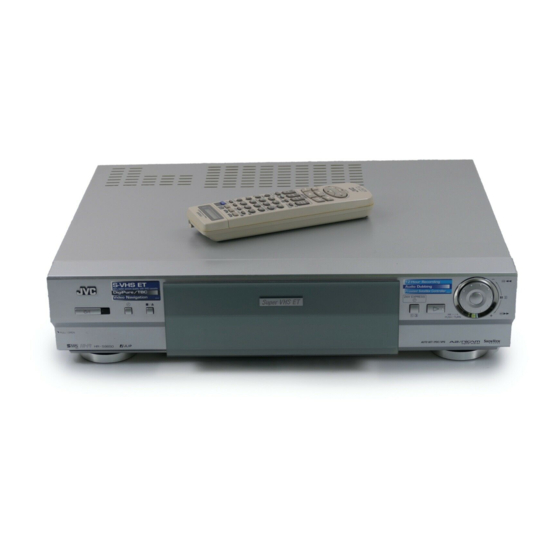
HR-S9850EU/EK
PULL/OPEN
(The specifications shown pertain specifically to the model HR-S9850EU)
, 50 Hz/60 Hz
d
24H EXPRESS
PR
PUSH/TURN
TUNER/TIMER
TV channel storage capacity
: 99 positions (+AUX position)
Tuning system
: Frequency synthesized tuner
Channel coverage : VHF 47 MHz – 89 MHz/
104 MHz – 300 MHz/
302 MHz – 470 MHz
UHF 470 MHz – 862 MHz
Aerial output
: UHF channels 22 – 69 (Adjustable)
Memory backup time
: Approx. 10 min.
ACCESSORIES
Provided accessories
: RF cable,
S-Video cable,
Satellite Controller,
Infrared remote control unit,
"R6" battery x 2
Specifications shown are for SP mode unless otherwise
specified.
E.& O.E. Design and specifications subject to change without
notice.
No.82889
July 2001
Advertisement
Table of Contents


Need help?
Do you have a question about the HR-S9850EU and is the answer not in the manual?
Questions and answers