Table of Contents
Advertisement
Quick Links
SERVICE MANUAL
VIDEO CASSETTE RECORDER
VCR TV CABLE/DBS
A.MONITOR
POWER
A/B
TV/VCR
DISPLAY
ENTER/OSD
1
2
3
. , ?
ABC
DEF
2
4
5
6
DHI
JKL
MNO
DBS
DAILY(M-F)
WEEKLY
7
8
9
PQRS
TUV
WXYZ
C. RESET
AUX
0
4
CANCEL
TIMER
START
STOP
DATE
CH
EXPRESS PROGRAMMING
1
PROG
SP/EP
PROG
SKIP SEARCH
CHECK
PLAY
STOP
TV CH +
TV
TV
VOL
VOL
–
+
TV CH –
JOG/
SHUTTLE
SPECIFICATIONS
GENERAL
Power requirement
: AC 120 V` , 60 Hz
Power consumption
Power on
: 27 W
Power off
: 2.6 W
Temperature
Operating
: 5°C to 40°C (41°F to 104°F)
Storage
: –20°C to 60°C (–4°F to140°F)
Operating position
: Horizontal only
Dimensions (W x H x D) : 437 mm x 97 mm x 347 mm
(17-1/4" x 3-7/8" x 13-11/16")
Weight
: 4.8 kg (10.6 lbs)
Format
: S-VHS/VHS NTSC standard
Maximum recording time
SP
: 210 min. with ST-210 video cassette
EP
: 630 min. with ST-210 video cassette
VIDEO/AUDIO
Signal system
: NTSC-type color signal and EIA
monochrome signal, 525 lines/60 fields
Recording/
Playback system
: DA-4 (Double Azimuth) head helical
scan system
Signal-to-noise ratio
: 45 dB
Horizontal resolution
VHS
: 230 lines
S-VHS
: 400 lines
Frequency range
Normal audio
: 70 Hz to 10,000 Hz
Hi-Fi audio
: 20 Hz to 20,000 Hz
Input/Output
: RCA connectors (IN x 2, OUT x 1)
S-video connectors (IN x 2, OUT x 1)
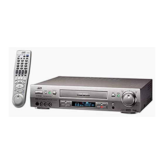
HR-S9800U
This service manual is printed on 100% recycled paper.
COPYRIGHT © 2000 VICTOR COMPANY OF JAPAN, LTD.
TUNER
Tuning system
: Frequency-synthesized tuner
Channel coverage
VHF
: Channels 2–13
UHF
: Channels 14–69
CATV
: 113 Channels
RF output
: Channel 3 or 4 (switchable; preset
to Channel 3 when shipped) 75 Ω,
unbalanced
TIMER
Clock reference
: Quartz
Program capacity
: 1-year programmable timer/
8 programs
Memory backup time
: Approx. 3 min.
ACCESSORIES
Provided accessories
: Infrared remote control unit,
"AA" battery x 2,
Audio/video cable,
RF cable (F-type),
S-video cable (4-pin),
S-VHS ET labels,
Controller
Specifications shown are for SP mode unless specified otherwise.
E. & O.E. Design and specifications subject to change without notice.
No. 82805
June 2000
Advertisement
Table of Contents

Related Manuals for JVC HR-S9800U


Summary of Contents for JVC HR-S9800U
-
Page 1: Specifications
SERVICE MANUAL VIDEO CASSETTE RECORDER HR-S9800U VCR TV CABLE/DBS A.MONITOR POWER TV/VCR DISPLAY ENTER/OSD . , ? DAILY(M-F) WEEKLY PQRS WXYZ C. RESET CANCEL TIMER START STOP DATE EXPRESS PROGRAMMING PROG SP/EP PROG SKIP SEARCH CHECK PLAY STOP TV CH + –... -
Page 2: Table Of Contents
TABLE OF CONTENTS Section Title Page Section Title Page Important Safety Precautions 3.1.3 Color (colour) bar signal,Color (colour) bar pattern ... 3-1 3.1.4 Switch settings and standard precautions ....3-1 INSTRUCTIONS 3.1.5 EVR Adjustment ............3-1 3.2 SERVO CIRCUIT ............3-2 1. -
Page 3: Important Safety Precautions
Important Safety Precautions Prior to shipment from the factory, JVC products are strictly inspected to conform with the recognized product safety and electrical codes of the countries in which they are to be sold. However, in order to maintain such compliance, it is equally important to implement the following precautions when a set is being serviced. -
Page 4: Safety Check After Servicing
• Safety Check after Servicing Examine the area surrounding the repaired location for damage or deterioration. Observe that screws, parts and wires have been returned to original positions, Afterwards, perform the following tests and confirm the specified values in order to verify compliance with safety standards. -
Page 6: Disassembly
SECTION 1 DISASSEMBLY 1.3 DISASSEMBLY/ASSEMBLY METHOD 1.1 DISASSEMBLY FLOW CHART STEP This flowchart lists the disassembling steps for the cabinet FIG. /LOC PART NAME POINT NOTE parts and P.C. boards in order to gain access to item(s) to be serviced. When reassembling, perform the step(s) in Top cover 4(S1) reverse order. - Page 7 Procedures for Lowering the Cassette holder assembly (L2a) (L2b) As the mechanism of this unit is integrated with the Housing assembly, the holder must be lowered and the two screws un- screwed when removing the Mechanism assembly. Fig. 2 (L2b) EARTH PLATE <NOTE 2>...
- Page 8 A/C head base WR4b SUPPORTING TAPE SIDE WR4a <NOTE 4a> FOIL SIDE <NOTE 4a> CN901 (L4a) FOIL SIDE <NOTE4a> (S6b) CN902 <NOTE6b> (S6a) <NOTE6a> (S6b) CN3012 <NOTE4b> WR4c FOIL SIDE (L4a) <NOTE4a> Q3003 (L4a) End sensor (L6) <NOTE6a> WR4a Spacer WR4b <NOTE6a>...
-
Page 9: Service Position
(5) Take out 2 screws C , 1 screw D and 1 screw E as (S8c) shown in Fig. 1-4-1. (L8) (6) Take out 1 screw F as shown in Fig. 1-4-1, and remove CN1902 the GR board assembly. (Take care not to pull the flat FOIL SIDE (S8a) <NOTE4a>... -
Page 10: Precautions For Cassette Loading In The "Service Position
want to switch the mode, turn the set to the normal po- Note: • When carrying out diagnosis and repair of the Main sition (the status shown in Fig.1-4-3). board assembly in the service position, be sure to • In the "SERVICE POSITION", the cassette tabs cannot ground both the Main board and the Mechanism as- be detected and recording becomes possible even with semblies. -
Page 11: Emergency Display Function
1.6.1 Displaying the emergency information 1.6 EMERGENCY DISPLAY FUNCTION (1) Transmit the code “59” from the Jig RCU. This unit has a function for storing the history of the past two The FDP shows the emergency content in the form of emergencies (EMG) and displaying them on each FDP. -
Page 12: Emergency Content Description
1.6.3 Emergency content description Note: Emergency contents “E08/E09” are for the model with Dynamic Drum (DD). CONTENT CAUSE 1 The mechanism is locked in the middle of mode transition. E01: Loading EMG When the mechanism mode cannot be changed to an- 2 The mechanism is locked at the loading end due to the encoder position other mode even when the loading motor has rotated for more than 4 seconds in the loading direction, [E:01]... -
Page 13: Emergency Detail Information 1
1.6.4 Emergency detail information : Mechanism Operation Mode [Table of MN] The status (electrical operation mode) of the VCR and the sta- tus (mechanism operation mode/sensor information) of the Display Mechanism Operation Mode Command standby (Status without executing command) mechanism in the latest emergency can be confirmed based on POWER OFF by EMG occurrence the figure in EMG detail information Moving to the adjacent position in the LOAD direction... - Page 14 1.6.5 Emergency detail information : Mechanism Sensor Information 3 – [Common table of MN and HD] The type of the cassette tape and the cassette tape winding po- sition can be confirmed based on the figure in EMG detail infor- Mechanism Sensor Information Display S-VHS SW...
-
Page 15: Syscon Circuit
1.7 SYSCON CIRCUIT 1.7.1 Syscon CPU pin function (IC3001) 1/2 PIN NO. LABEL IN/OUT FUNCTION CTL(+) IN/OUT CTL(+) SIGNAL SVSS CTL(-) IN/OUT CTL(-) SIGNAL CTLBIAS CTL BIAS VOLTAGE CTLFB CTL PULSE FEEDBACK CTLAMPOUT CTL PULSE OUTPUT CTLSMTIN CTL PULSE INPUT CAPSTAN FG PULSE INPUT SVCC SYSTEM POWER... -
Page 16: Syscon Cpu Pin Function (Ic3001) 1/2
1.7.2 Syscon CPU pin function (IC3001) 2/2 PIN NO. LABEL IN/OUT FUNCTION TU_CE CHIP ENABLE OF THE TUNER UNIT N.REC_ST(H) NORMAL AUDIO SOUND RECORDING START DD_FG DYNAMIC DRUM FG INPUT TU_CLK CLOCK FOR DATA TRANSFER TO THE TUNER UNIT TU_DATA TUNING DATA NMI(L) TIMER CLOCK (32.768KHz) -
Page 17: Servicing The Video Navigation Function
1.8 SERVICING THE VIDEO NAVIGATION FUNCTION (1) Turn [OFF] the power of the 2 units (slave and master) The video navigation function is to record data to the built-in VCR and set it without a cassette tape. FLASH memory of the VCR. At the same time a reference number is wrote on the cassette tape for control purposes. -
Page 18: Erasing The Video Navigation Data (Initialization)
1.8.2 Erasing the video navigation data (Initialization) This is the service mode to erase all the video navigation Fig. 1-8-2b CH 1 data inside the FLASH memory. When a unit is replaced or after an operations check, erase the data which is not re- quired while observing the TV screen. -
Page 19: Mechanism Adjustment
SECTION 2 MECHANISM ADJUSTMENT 2.1 BEFORE STARTING REPAIR AND ADJUSTMENT 2.1.1 Precautions (1) Unplug the power cable of the main unit before using your Loading motor soldering iron. (2) Take care not to cause any damage to the conductor wires when plugging and unplugging the connectors. (3) Do not randomly handle the parts without identifying where the trouble is. -
Page 20: Jigs And Tools Required For Adjustment
2. In case of mechanical failure 2.1.4 Jigs and Tools Required for Adjustment If you cannot remove the cassette tape which is loaded be- Roller driver A/C head positioning tool Torque gauge cause of any mechanical failure, manually remove it by tak- PTU94002 PTU94010 PUJ48075-2... -
Page 21: Maintenance And Inspection
2.1.5 Maintenance and Inspection 1. Location of major mechanical parts In this chapter, the two mechanism speeds are described by comparing the speeds of the standard type and the high-speed FF/REW type. It is possible to distinguish between these two types of mechanism by the diameters of their capstan pulleys. The capstan pulley diameter for the standard type is approx. - Page 22 4. Suggested servicing schedule for main components The following table indicates the suggested period for such Guide rail Roller cam assembly service measures as cleaning,lubrication and replacement. In practice, the indicated periods will vary widely according to environmental and usage conditions.However, the indi- cated components should be inspected when a set is brought for service and the maintenance work performed if neces- sary.
- Page 23 Symbols and numbers R4 R1 T9 T12 T11 B15 B12 B14 B13 B17 B21 B7 B8 B5 B4 B11 T14 T15 T13 T22 T24 T18 B19 Removal parts (Reference items) Replacement parts 2.2.3 Guide rail 2.2.3 Roller cam assembly 2.2.3 Cassette housing bracket 2.2.3 Opener guide 2.2.3 Door opener 2.2.3 Relay gear...
-
Page 24: Replacement Of Major Parts
2.2 REPLACEMENT OF MAJOR PARTS 2.2.3 Cassette Holder Assembly 1. How to remove 2.2.1 Before Starting Disassembling (Phase matching (1) Remove the guide rail and roller cam assembly. (See between mechanical parts) Fig.2-2-3a.) The mechanism of this unit is closely linked with the rotary (3 lugs on the guide rail and one lug on the roller cam encoder and system controller circuits. - Page 25 (5) While holding the left side of the cassette holder, lift the 2. How to install (Phase matching) Å ı cassette holder assembly so that the three legs on the (1) Insert the section of the drive arm into the section Å...
-
Page 26: Pinch Roller Arm Assembly
2.2.6 Audio Control Head Notches Guide hole Notch 1. How to remove Relay gear (1) Remove the two screws (A) and remove the audio con- trol head together with the head base. (2) When replacing only the audio control head, remove the three screws (B) while controlling the compression spring. -
Page 27: Capstan Motor
2. How to install (Centering the mounting position) Loading motor board assembly When the capstan motor has once been removed and then reinstalled out of the initial correct position in the rotational Loading motor direction, the capstan motor current may be unstable during Lugs operation in high or low temperatures. -
Page 28: Rotary Encoder
2.2.10 Rotary Encoder 2.2.12 Change Lever Assembly, Direct Gear, Clutch Gear and Coupling Gear 1. How to remove (1) Remove the screw (A) and remove the rotary encoder 1. How to remove by pulling it up. (See Fig. 2-2-10a.) (1) Release the two lugs of the rotary encoder guide in the arrow-indicated direction and remove the change lever assembly. -
Page 29: Link Lever
2.2.13 Link Lever 2.2.14 Cassette Gear, Control Cam and Worm Gear 1. How to remove 1. How to remove (1) Remove the two slit washers. (1) Remove the control cam by lifting it. (2) Remove the link lever by lifting it from the shaft retained (2) Open the two lugs of the cassette gear outward and pull by the slit washers. -
Page 30: Loading Arm Gear (Supply Or Take-Up Side) And Loading Arm Gear Shaft
(3) Install the control plate so that the section A of the load- (3) Turn the loading arm gear (take-up side) clockwise so ing arm gear shaft fits into the hole (A) of the control plate, that the notch of the loading arm gear (take-up side) is the section B of the control plate guide into the hole (B), in alignment with the projection of the loading arm gear and the control plate comes under the section C of the... -
Page 31: Take-Up Lever, Take-Up Head And Control Plate Guide
2.2.17 Take-up Lever, Take-up Head and Control Plate Guide (1) Remove the spring of the take-up lever from the main deck. Spring (2) Remove the lug (A) of the take-up lever from the main Sub brake assembly deck and pull out the take-up lever and the take-up head Lug(A) (take-up side) together. -
Page 32: Tension Brake Assembly, Reel Disk (Supply Side) And Tension Arm Assembly
2.2.21 Tension Brake Assembly, Reel Disk (supply side) 2.2.23 Stator Assembly and Tension Arm Assembly (1) Remove the flat cable. 1. How to remove (2) Remove the two screws (A). (1) Remove the three lugs of the tension brake assembly (3) Remove the stator assembly by lifting in the arrow-indi- from the main deck and pull them off. -
Page 33: Upper Drum Assembly
2.2.25 Upper Drum Assembly 1. How to remove (1) Remove the stator assembly and rotor assembly. (2) Loosen the screw of the collar assembly using a 1.5 mm hexagonal wrench and remove the collar assembly. Also remove the brush, spring and cap at one time. Lower drum assembly (3) Remove the upper drum assembly and remove the washer using tweezers. -
Page 34: Compatibility Adjustment
2.3 COMPATIBILITY ADJUSTMENT (5) Reduce the V.PB FM waveform while pressing the chan- nel buttons (+, –) during playback. If a drop in level is Notes: found on the left side, turn the guide roller of the pole • Although compatibility adjustment is very important, base assembly (supply side) with the roller driver to make it is not necessary to perform this as part of the nor- the V.PB FM waveform linear. -
Page 35: Checking/Adjustment Of The Height And Tilt Of The Audio Control Head
(3) Press the channel buttons (+, –) simultaneously to enter the manual tracking mode. This also brings tracking to the center (centre). (4) Adjust the AUDIO OUT waveform and Control pulse waveform by turning the screws (1), (2) and (3) little by little until both waveforms reach maximum. -
Page 36: Checking/Adjustment Of The Standard Tracking Preset
[Perform adjustments steps (7) to (10) only for 2 Head (1) Play back the alignment tape (A). models equipped with LP mode.] (2) Apply the external trigger signal to D.FF (E), to observe the V.PB FM waveform at the measuring point (D). (7) Then play back the alignment tape (A2). -
Page 37: Mechanism Timing Chart
Mechanism Timing Chart EJECT CASS- Mechanism mode CASS-INS FF/REW STOP SLOW/STILL PLAY Control plate mark HIGH C CH HIGH Rotary encoder B CH HIGH A CH Control cam angle 264. 318. 412. Rotary encoder 114. 150. 167. 178. 207. 218. 240. -
Page 38: Electrical Adjustment
SECTION 3 ELECTRICAL ADJUSTMENT 3.1 PRECAUTION Jig RCU The following adjustment procedures are not only necessary [Data transmitting method] Depress the “ ” ( 3 ) button after replacement of consumable mechanical parts or board after the data code is set. assemblies, but are also provided as references to be re- ferred to when servicing the electrical circuitry. -
Page 39: Servo Circuit
(1) Record the signal (A2) in the mode (B1), and play back the recorded signal. (2) Press the channel buttons (+, –) simultaneously to enter the manual tracking mode. This also brings tracking to the center (centre). (3) Set the VCR to the FWD slow mode. (4) Transmit the code (F) from the Jig RCU to adjust so that Fig. -
Page 40: Video Circuit
3.3 VIDEO CIRCUIT 3.3.1 D/A level • Signal (A1) Ext. S-input / Ext. input • (A2) Color (colour) bar signal [NTSC] Y level • (A3) S-VHS tape • Mode S-VHS • H. rate • Equipment Oscilloscope Fig. 3-3-2a EE Y level •... -
Page 41: Rec Color (Colour) Level
3.3.4 REC color (colour) level • Signal (A1) Alignment tape(S-VHS, SP/EP, Color(colour) bar) [MH-1H] Specified • value (G) (A2) Ext. input • (A3) Color (colour) bar signal [NTSC] • Mode (B1) S-VHS SP • (B2) S-VHS EP V. rate • Equipment Oscilloscope Fig. -
Page 42: Auto Picture Initial Setting
3.3.6 AUTO PICTURE initial setting • Signal (A1) Ext. input • Specified (A2) Video: Optional Specified value (G1) value (G2) • (A3) VHS tape • EE ¥ Auto adjust (SP/EP REC ¥ PB) Mode V. rate • Adjustment part Jig RCU : Code “58” Fig. -
Page 43: Stereo Filter
(3) Set the VCR to the EVR mode by transmitting the code (5) Adjust with the channel buttons (+,–) on the VCR (or on (F1) from the Jig RCU. the remote controller) so that the level of the measuring (4) Set the EVR address to (F2) by pressing the button of point (D) becomes the specified value (G). - Page 44 JVC SERVICE & ENGINEERING COMPANY OF AMERICA DIVISION OF JVC AMERICAS CORP. Head office 1700 Valley Road Wayne, New Jersey 07470-9976 (973)315-5000 (973)396-1000 East Coast 10 New Maple Avenue Pine Brook, New Jersey 07058-9641 705 Enterprise Street Aurora, Illinois 60504-8149...
Need help?
Do you have a question about the HR-S9800U and is the answer not in the manual?
Questions and answers