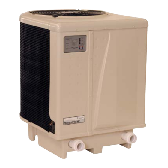
Summary of Contents for Pentair ThermalFlo Heat Pump Contol Panel Addendum
- Page 1 ™ ThermalFlo Heat Pump Autoset Control Board Addendum IMPORTANT SAFETY INSTRUCTIONS READ AND FOLLOW ALL INSTRUCTIONS SAVE THESE INSTRUCTIONS...
-
Page 2: Table Of Contents
ThermalFlo Heat Pump Contol Panel Addendum The information in this addendum supercedes information in the ThermalFlo Installation and User’s Guide (P/N 473426 Rev. C 10/19/06). For additional information not covered in this addendum, please refer to the above-named manual. ThermalFlo Heat Pump Control Panel Overview ................... 1 Control Panel Layout ............................ -
Page 3: Thermalflo Heat Pump Control Panel Overview
THERMALFLO HEAT PUMP CONTROL PANEL OVERVIEW CONTROL PANEL LAYOUT 1. ON/OFF Pushbutton – Turns the heat pump On and Off. 2. MENU SELECT button – Use to select menu items. While in the Run screen, pressing this button displays the Control Panel Menu screen. Also, use this button to scroll through Operator Setup Menu screens 3. -
Page 4: Control Panel Operation
Stop the heat pump – With the ON light illuminated, press the ON/OFF button to stop the heat pump. The ON light will be off followed by the temporary screen shown below. PENTAIR WATER HEAT PUMP OFF 2. Adjusting the set point temperature – There are two (2) independently adjustable temperature setpoints for the pool and spa. - Page 5 4. Heat, Cool and Auto Modes Operation - Certain heat pump models have the ability to both heat and cool. a. These heat pumps can be setup to operate in any one of three modes: • Heat only mode • Cool only mode •...
-
Page 6: Control Panel Menu Screens
6. AutoSet – Certain heat pump models have the ability to start and stop a remote water pump. This AutoSet feature, if enabled, allows the heat pump to periodically energize the filter pump and test the temperature of the water in the pool or spa. If the water requires heating, or cooling if available, the filter pump will remain energized until the water reaches the set point temperature. - Page 7 4. Remote On/Off Screen – Allows the operator to turn the Relay Remote mode On and Off. In Relay Remote mode, the heat pump is started and stopped by remote relays in an automation controller. The local Pool and Spa setpoints are still active in this Relay Remote mode. REMOTE REMOTE IS ON/OFF 5.
-
Page 8: Operator Setup Menu Screens
OPERATOR SETUP MENU SCREENS To access this menu, press the Up and Down arrow simultaneously. While in the Operator Setup Menu screen, if no activity is detected after 15 seconds the main screen is displayed. To get back into the Setup menu you must press the Up and Down arrow simultaneously again. 1. -
Page 9: Locking The Control Panel
The last number shown on the display will become active. TEMP OFFSET OFFSET = -2 TO +2 7. Defrost – Allows the operator to turn the defrost feature on or off. Adjusted to enable or disable with the UP and DOWN arrow buttons. DEFROST ENABLE / DISABLE 8. -
Page 10: Autoset
AUTOSET Autoset is a feature that allows the heat pump to automatically turn on your water circulation pump at predetermined time intervals after the water circulation pump shuts off. To utilize this feature, the water circulation pump must be wired in parallel with your mechanical time clock using the auxiliary relay supplied in the high voltage power panel of the heat pump. -
Page 11: Control Panel Alarm Messages
CONTROL PANEL ALARM MESSAGES . ° . ° c t i o l f a t l t s i t i u t s i t i u t s i t i u t s i t i u a t l c t i c t i... -
Page 12: Thermalflo Heat Pump Wiring Diagram
RS-485 INTELLITOUCH CONNECTION INPUT OUTPUTS 3 - WIRE SWITCHES TEMP TEMP REMOTE TERM. THERM1THERM2 24 VAC POOL YELLOW WHITE BLUE WHITE/RED WHITE WHITE 10K ohm BLUE /RED Thermistors WHITE/RED YELLOW PURPLE WHITE WHITE WHITE WHITE PURPLE BLACK BLACK BLACK BLACK BLACK BLACK Optional... -
Page 13: Autoset Contactor To Mechanical Timer Wiring Example
AutoSet Contactor to Mechanical Timer Wiring Example Intermatic CLOCK T104 MOTOR Timer 240V SUPPLY GROUND FILTER PUMP LINE 1 LINE 2 GROUND AutoSet Contactor NOTES: 1. Mechanical timer is not provided with the heat pump 2. Example only, other timers will be similarly wired 3. -
Page 14: Replacement Parts List
Replacement Parts List SCALE 1 : 4 ThermalFlo Addendum... - Page 15 Replacement Parts List (Continued) Item No. Part Number Description 473665 Probe Thermister Defrost Sensor 470284 Nut, J-Clip 473285 Nut, 1/4 - 20 SS Acorn 470281 Nut, U-Clip 470147 Wire Harness, Compressor 473024 Compressor, Trane GH633-LL1-G (Model # 500, 700, 900) 473025 Compressor, Trane GH673-LL1-G (Model # 1200, 1200R) 473295...
- Page 16 Web sites: www.pentairpool.com - www.staritepool.com © 2007 Pentair Water Pool and Spa, Inc. All rights reserved 1620 Hawkins Ave., Sanford, NC 27330 • (919) 566-8000 10951 West Los Angeles Ave., Moorpark, CA 93021 • (805) 553-5000 P/N 472747 Rev B 5-17-07...


Need help?
Do you have a question about the ThermalFlo Heat Pump Contol Panel Addendum and is the answer not in the manual?
Questions and answers