Omron NT31 Setup Manual
Programmable
Hide thumbs
Also See for NT31:
- Operation manuals (707 pages) ,
- Setup manual (313 pages) ,
- Reference manual (480 pages)
Table of Contents
Advertisement
Quick Links
Advertisement
Chapters
Table of Contents
Troubleshooting

Related Manuals for Omron NT31


Summary of Contents for Omron NT31
- Page 1 Cat. No. V062-E1-03 NT31 and NT31C Programmable Terminals Setup Manual...
- Page 2 NT31and NT31C Programmable Terminals Setup Manual Revised June 2004...
- Page 4 OMRON. No patent liability is assumed with respect to the use of the information contained herein. Moreover, because OMRON is constantly striving to improve its high-quality products, the information contained in this manual is subject to change without notice.
-
Page 6: Table Of Contents
........Role and Operation of the NT31/NT31C . - Page 7 ........D Transporting and Storing the NT31/NT31C .
-
Page 8: About This Manual
About this Manual: This manual describes connecting the NT-series NT31 and NT31C Programmable Terminals to a PLC (Programmable Controller) or other host and peripheral devices and the settings required for communica- tions and applications. It includes the sections described below. - Page 9 Programmable Terminal Functions and Operation S NT31/31C/631/631C PT Reference Manual (V064-E1-j) This manual is used for any of the following PTs: NT31, NT31C, NT631, and NT631C. It describes screen configurations, part functions, host control meth- ods, and other application information.
-
Page 10: Precautions
PRECAUTIONS This section provides general precautions for using the Programmable Terminal. The information contained in this section is important for the safe and reliable application of the Programmable Ter- minal. You must read this section and understand the information contained before attempting to set up or operate a Programmable Terminal. -
Page 11: Intended Audience
Meanings This operation manual uses the following conventions and symbols to indicate cautions, warnings, and dangers in order to ensure safe use of the NT31/31C. The cautions, warnings, and dangers shown here contain important information related to safety. The instructions in these cautions, warnings, and dangers must be observed. - Page 12 Doing either of these may result in electrical shock. WARNING Switch OFF the NT31/NT31C power before replacing the backlight. Otherwise you could sustain an electric shock. CAUTION Do not touch the backlight immediately after switching OFF the power supply.
-
Page 13: General
........1-1-1 Operation of an NT31/NT31C at an FA Production Site .... -
Page 14: Role And Operation Of The Nt31/Nt31C
The following gives a general description of the role and operation of the NT31/NT31C for those using a programmable terminal (PT) for the first time. 1-1-1 Operation of an NT31/NT31C at an FA Production Site... -
Page 15: Section
Receives Data from a The NT31/NT31C can be connected to the host by a host link or NT link and re- Host ceive necessary data from the host. Host link, NT link... -
Page 16: Functions Of The Nt31/Nt31C
* When mounted in a panel of the recommended thickness (page 30). Construction Best Suited to the FA Environment • The panel is an STN monochrome LCD type with backlight for the NT31 and an STN color LCD type with backlight for the NT31C. -
Page 17: Comparison Between Nt31 And Nt31C
9 words can be changed from the Host to open, close, and move windows. 1-2-2 Comparison between NT31 and NT31C Two NT31 models — the NT31, which is capable of versatile graphic displays, and the NT31C, which is also capable of color display — are available. The dif-... -
Page 18: Comparison Between Nt30/Nt30C And Nt31/Nt31C
NT30/NT30C or NT620S/NT620C/NT625C in the functions listed below. The PT retains full V2 functionality in all functions other than the ones listed below. Refer to Appendix C in the NT31/NT31C/NT631/NT631C Programmable Termi- nal Reference Manual for more details. • Word configuration and functions of the PT status control area and PT status notify area •... - Page 19 *3: The values are the same as the NT30/NT30C when the PT is in NT30/620 compatible mode. *4: The window control area can be used only in the Vj versions of the NT31/NT31C. For differences in programming, refer to Appendix B in the NT31/NT31C/NT631/NT631C Programmable Terminal Refer-...
-
Page 20: Principal Functions Of Nt31/Nt31C
Functions of the NT31/NT31C Section 1-2-5 Principal Functions of NT31/NT31C The following are the principal functions of the NT31/NT31C. Functions relating to data display Character display Characters of various sizes can be displayed. Characters can be flashed and displayed in reverse video. - Page 21 Communications with the host The NT31/NT31C can communicate with the host by four methods: host link, 1:1 NT Link, 1:N NT link (standard or high-speed), and Memory link. Data can be read from the host, and data input by means of touch switches and numeral/character string settings can be sent to the host.
-
Page 22: Displays
The NT31/NT31C can display various kinds of elements such as characters, nu- meric values, graphs, lamps, and touch switches, on a screen. The screen data displayed by the NT31/NT31C are created by using the Support Tool at a per- sonal computer. - Page 23 Section Library data are combinations of fixed display graphics registered as a single graphic. They are registered in advance and as many as required can be dis- played at any position on the screen. Since it is generated by combining graphics, library data has a small data size. Mark Image data Library data Lamps...
- Page 24 The input character strings can also be stored in a character string memory table and notified to the host. String inputs can be enabled and disabled from the host when an interlock bit has been allocated. Character string setting input field Display NT31C Input NT31C NT31 NT631C...
- Page 25 Section Thumbwheel Switches Numeric values can be input by incrementing or decrementing each digit with the corresponding touch switch (+, –). The input numeric values can also be stored in a numeral memory table and notified to the host. Thumbwheel switch inputs can be enabled and disabled from the host when an interlock bit has been allocated.
- Page 26 ON are recorded and displayed together with the message (charac- ter string) set for the bit memory table. The NT31/NT31C allows selection of the display order as the newest record first or the oldest record first by memory switch setting.
-
Page 27: System Configuration
System Configuration Section System Configuration This section shows the configuration of a system that uses an NT31/NT31C. For details on product models, refer to Appendix J Model List (page 279). 1-3-1 Peripheral Devices That Can Be Connected The following peripheral devices can be connected to an NT31/NT31C. -
Page 28: Communications With The Host
(1:1) communication method, RS-485 cannot be used. The connection must be made with RS-232C or RS-422A. Communications with the Host The NT31/NT31C is connected to the host by one of the following communica- tion methods. The following communications can be used to connect an OMRON PLC: •... -
Page 29: Host Link
The direct connection function allows the data to be displayed at the NT31/NT31C to be read from the memory area in the PLC and written to memory tables in the NT31/NT31C. Also, the data input at the NT31/NT31C can be writ- ten to the memory area in the PLC. - Page 30 NT31/NT31C switches to the monitor mode when the PLC is in the RUN mode.) • In the case of PTs that support the standard 1:N NT Link (NT20S, NT31, NT31C, NT600S, NT620S, NT620C, NT625C, NT631, NT631C) up to 8 PTs can be connected to one port of the PLC and used at the same time.
-
Page 31: Communications Using Memory Links
In memory link, there is an area called PT Memory, as shown below, inside the NT31/NT31C, and this area is treated as a virtual area on the PLC. This allows PT memory and the display elements of the NT31/NT31C to make a quasi-direct connection. -
Page 32: Comparison Between Direct Connection And Memory Link
1-5-3 Memory Link Online Transfer Function When memory link communications are being used, the NT31/NT31C can be switched to Transmit mode from the host even if the NT31/NT31C is operating and screen data can be written. (The NT31/NT31C can be returned to RUN mode after the screen data is written.) -
Page 33: Before Operating
Before Operating Section Before Operating Follow the procedure given below to start the system of the NT31/NT31C. Host Support Tool NT31/NT31C Set the host settings. Install the Support Install the PT in the Tool at the computer. operation panel. • For the host link, refer to... - Page 34 Before Operating Section Device or Software Manual Title Manual Number SYSMAC CPM1 Operation Manual W262-E1-j SYSMAC CPM1A Operation Manual W317-E1-j SYSMAC CPM2A Operation Manual W352-E1-j SYSMAC CPM2C Operation Manual W356-E1-j SYSMAC C200H Operation Manual (for CPU01/03/11) (programming) W130-E1-j SYSMAC C200H Operation Manual (for CPU21/23/31) (programming) W217-E1-j SYSMAC C200HS Installation Guide W236-E1-j...
-
Page 35: Preparing For Connection
SECTION 2 Preparing for Connection This section describes the connection methods that are possible with the PTs, and the functions of the parts of PTs, as the required knowledge before connecting to the host and to the peripheral devices. Method for Connection to the Host . -
Page 36: Method For Connection To The Host
This section describes the methods for connection to the host used with the NT31/NT31C, and the relationship between the connection method and the communication method. NT31/NT31C Communication Ports and Communication Methods The NT31/NT31C has two communication ports. Their uses are indicated in the table below. Communication Usable Communication Methods... - Page 37 Combinations of Communication Method and Connection Method The connection methods that can be used depending on the communication method used and the communication type for communication between the NT31/NT31C and the host are indicated in the table below. Usable Communication Method...
- Page 38 6 of the RS-232C connector. Check the signals of the RS-232C connector at the host. • +5 V is not output from serial port B of the NT31/NT31C. When connecting an NT-AL001 at serial port B, a separate power supply is required for the NT- AL001.
-
Page 39: Names And Functions Of Parts
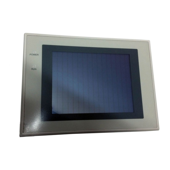
Names and Functions of Parts Section Names and Functions of Parts Before starting operation, the names and functions of the parts of the NT31/NT31C are described here as a confirmation. A method of hardware set- tings is also described. Front View POWER LED Lit in green when the power is supplied. - Page 40 Serial port B connector Connect the cable for connection to the host here. Depending on the setting made at the NT31/NT31C system menu, either RS-232C or RS-422A/485 may be used. This is a 25-pin connector. It is not possible to use RS-232C and RS-422A/485 at the same time.
-
Page 41: Hardware Settings And Connections
SECTION 3 Hardware Settings and Connections This section describes the settings of the PTs and methods for connection to peripheral devices. For details on connecting to the host, refer Section 4 Connecting to the Host from the RS-232C Port or Section 5 Connecting to the Host from the RS-422A/485 Port. -
Page 42: Installation
• Potential exposure to radioactivity 3-1-2 Installation in the Operation Panel The NT31/NT31C is mounted in an operation panel by embedding it in the panel. Use the panel fittings and tool (Philips screwdriver) included in the product pack- age and follow the procedure below. -
Page 43: Power Supply Connection
0.5 to 0.6 N⋅m in order to ensure water- and dust-resistance. Front sheet of NT31/NT31C may be warped if the tightening is too strong or not uniformity. The panel must not be soiled or warped, and must be able to support an installation that will remain secure and strong. -
Page 44: Grounding
( ) of the NT31/NT31C. 2. If the NT31/NT31C is installed in the same panel as equipment that gener- ates noise, such as a motor or inverter, do not ground the functional ground terminal ( ) of the NT31/NT31C. -
Page 45: Connecting To The Support Tool
Section Connecting to the Support Tool In order to install the system program in the NT31/NT31C, or to transmit screen data created with the Support Tool to the NT31/NT31C, the NT31/NT31C must be connected to a personal computer with an RS-232C cable. -
Page 46: Connecting A Printer
The length of the cable should not exceed 1.5 m. Reference: If the connector cable is connected or disconnected while the power to the printer is on, the NT31/NT31C may malfunction. Always turn off the power to the printer before connecting or disconnecting the cable. -
Page 47: Connecting A Bar Code Reader
Note Make sure that the power supply to the bar code reader and the power supply to the PT are both OFF before connecting or disconnecting the cable. 3-4-1 Connection Method Connect the bar code reader to serial port A of the NT31/NT31C, as shown in the figure below. NT31/NT31C... -
Page 48: Data Format
During bar code reading, the NT31/NT31C performs RS/CS control. When the Input Method setting of the NT31/NT31C is set to Auto, the RS signal is turned OFF, prohibiting the next input, until the read data has been notified to the host. -
Page 49: Using A Memory Unit (-Vj Versions)
The memory unit functions are determined by the model of PT being used, re- gardless of the version of the system program installed in the PT. By installing a memory unit (NT-MF261) on the NT31/NT31C, the screen data in the NT31/NT31C can be recorded (backed up) in the memory unit. -
Page 50: Installation Method
Using a Memory Unit (-Vj Versions) Section S When a memory unit is mounted, the NT31/NT31C cannot be set to the oper- Reference: ating status. On completion of data transmission with a memory unit, always disconnect the memory unit from the NT31/NT31C before starting NT31/NT31C operation. - Page 51 (bank 0, bank 1). (The total data storage is for two PTs.) SW2-3 sets which of these two banks is used for automatic transmission. S The DIP switch function of the memory unit is supplemented to NT31/NT31C Reference: with the Vj suffix.
- Page 52 Use the following procedure to write the screen data in the NT31/NT31C to the memory unit by automatic transmission. 1, 2, 3... 1. Check that the power supply to the NT31/NT31C is OFF, then set the DIP switches of the memory unit as follows after installing memory unit to NT31/NT31C.
- Page 53 NT31/NT31C, this mode becomes convenient. Reference: When data is written to the NT31/NT31C, the data that has been stored up until that point is lost. When the system program is changed, the operation of NT31/NT31C also changes.
- Page 54 NT31/NT31C. Transmission can be executed while checking the settings. Reference: When data is written to the NT31/NT31C or memory unit, the data that has been stored up until that point is lost.
- Page 55 Bank 0: system program, Bank 1: other than system program Bank 0: other than system program, Bank 1: system program S When writing the system program into the NT31/NT31C, the type of system program inside memory unit and the type of PT unit must be corresponding.
- Page 56 OK touch switch, but in the case of other errors, the status described above re- mains in effect until the NT31/NT31C power is turned OFF or reset. When an error occurs, take remedial action by referring to the table below.
-
Page 57: Using A Memory Unit (Versions Without The -Vj Suffix)
NT31/NT31C or reset it. 3. Do not touch the PCB (printed circuit board) with bare hands. S When a memory unit is mounted, the NT31/NT31C cannot be set to the oper- Reference: ating status. On completion of data transmission with a memory unit, always disconnect the memory unit from the NT31/NT31C before starting NT31/NT31C operation. -
Page 58: Installation Method
DIP switches that are set at startup. Factory setting is turned all to off. Note 1. Always confirm that the power to the NT31/NT31C is off before setting the DIP switches. 2. Do not touch the PCB (printed circuit board) directly with bare hands. - Page 59 Use the following procedure to write the screen data in the NT31/NT31C to the memory unit by automatic transmission. 1, 2, 3... 1. Check that the power supply to the NT31/NT31C is OFF, then set the DIP switches of the memory unit as follows after installing the memory unit in NT31/NT31C.
- Page 60 Using a Memory Unit (Versions without the -Vj Suffix) Section Reference: When data is written to the NT31/NT31C, the data that has been stored up until that point is lost. Method of Execution Use the following procedure to write the screen data in the memory unit to the NT31/NT31C by automatic transmission.
- Page 61 4. Switch the NT31/NT31C power OFF, remove the memory unit, then switch the NT31/NT31C power back ON. Errors When Using a If an error occurs when using the memory unit, the NT31/NT31C operates as Memory Unit follows. • The details of the error and remedial action are displayed on the screen.
- Page 62 Section Error Probable Cause Remedial Action Flash memory error An error occurred during Turn the NT31/NT31C power initialization of the OFF, then back ON. If the error NT31/NT31C or memory recurs, the flash memory at the unit flash memory, or write destination may be faulty.
-
Page 63: Connecting To The Host From The Rs-232C Port
SECTION 4 Connecting to the Host from the RS-232C Port This section describes the method for connecting to the host using the RS-232C port of the PT. Connecting to the RS-232C Port at the Host ........4-1-1 Host Types and Settings . -
Page 64: Connecting To The Rs-232C Port At The Host
Direct Connection Between The RS-232C Ports Using an RS-232C Cable (Page 109) This is the easiest connection method. Depending on the host to which the con- nection is to be made, it may be possible to use OMRON cables with connectors. NT31/NT31C Host RS-232C cable (max. - Page 65 Connecting to the RS-232C Port at the Host Section The host units that can be connected to the NT31/NT31C by the host link method using the RS-232C ports of both units are indicated in the table below. CPUs Connectable with Host Link...
- Page 66 Unit # *1 Set the host link communications speed at 9600 bps or 19200 bps with the memory switch at the NT31/NT31C. For details, refer to Setting the Host Link Method (page 158). *2 The 1-to-N setting enables BCC (Block Check Character). It is not actually possible to connect more than one NT31/NT31C in a single host link.
- Page 67 Connecting to the RS-232C Port at the Host Section C1000H(F)/C2000H Backplane mounted type: 3G2A5-LK201-EV1 Setting the Front Switches Local Host Mode control (key switch) Set this to host link. Setting the Rear Switches @ I/O port selection (selector switch) Set this to RS-232C. @ Unit # (DIP SW1) I/O port RS-422A...
- Page 68 Connecting to the RS-232C Port at the Host Section C1000H/C2000H Backplane mounted type: C500-LK203 Setting the Rear Switches @ I/O port selection (selector switch) Set this to RS-232C. 5V supply @ Unit #, parity, and transfer code (DIP SW1-1 to SW1-7) I/O port RS-422A Set SW1-1 to SW1-7 to OFF (0).
- Page 69 (*2) 1-to-1, 1-to-N 1-to-N Instruction level Level 1, 2, 3 *1 Set the host link communications speed at 9600 bps or 19200 bps with the memory switch at the NT31/NT31C. For details, refer to Setting the Host Link Method (page158).
- Page 70 Section *2 The 1-to-N setting enables BCC (Block Check Character). It is not actually possible to connect more than one NT31/NT31C in a single host link. Set the CPU bus unit settings directly from a Programming Device (e.g. SYS- MAC support software).
- Page 71 Unit # *1 Set the host link communications speed at 9600 bps or 19200 bps with the memory switch at the NT31/NT31C. For details, refer to Setting the Host Link Method (page 158). Either set PLC Setup directly from a Programming Device (e.g. SYSMAC sup- port software), or transmit the PLC Setup made at a Programming Device to the CPU.
- Page 72 Connecting to the RS-232C Port at the Host Section Setting the Front Switches @ I/O port selection (selector switch) Set this to RS-232C. @ System setting (DIP SW4) To effect the existing DIP switch settings, set SW4 to ON. To effect the existing PLC Setup, set SW4 to OFF.
- Page 73 Unit # *1 Set the host link communications speed at 9600 bps or 19200 bps with the memory switch at the NT31/NT31C. For details, refer to Settings the Host Link Method (page158). Set the PLC Setup area settings directly from a Programming Device (e.g. the CX-Programmer support software).
- Page 74 Connecting to the RS-232C Port at the Host Section C200HX/HG/HE(-Z)E: Serial Communications Board port B Word # Writing Value Settings DM6550 0001 Host link mode, no CTS control Communication conditions set by the contents of DM DM6551 0303 Data length 7 bits, 2 stop bits, even parity, communications speed: 9600 bps 0304 Data length 7 bits, 2 stop bits, even parity,...
- Page 75 Connecting to the RS-232C Port at the Host Section When using the CQM1H’s built-in peripheral port, turn ON SW7. Setting the Switches of a CPM2A When using a CPM2A, the switches on the front panel must be set as shown below in order to make the PLC Setup settings effective.
- Page 76 *1 Set the host link communications speed at 9600 bps or 19200 bps with the memory switch at the NT31/NT31C. For details, refer to Settings the Host Link Method (page 158). When the communication speed is set to 19200 bps, the PLC Setup of the CPU need to be changed.
- Page 77 Connecting to the RS-232C Port at the Host Section Setting the Front Switches Set the CPU DIP switches to 4 or 5 in accordance with the port NT31/NT31C is connected to. ERR/ALM PRPHL/COMM SYSMAC CS1G PROGRAMMABLE CONTROLLER CPU4 Peripheral port...
- Page 78 Connecting to the RS-232C Port at the Host Section The host units that can be connected to the NT31/NT31C by the NT link (1:1) method using the RS-232C ports of both units are indicated in the table below. CPUs Connectable with...
- Page 79 Connecting to the RS-232C Port at the Host Section Settings at The Host The setting methods for each unit are as follows: Connecting to a C-series C200HS, C200HX/HG/HE(-Z)E, CPM1, CPM2A, CPM2C, CQM1, CQM1H, or SRM1 PLC Setup Area Settings Write the PLC Setup area (data memory) settings directly from a Programming Device (e.g.
- Page 80 Connecting to the RS-232C Port at the Host Section the front panel must be set as shown below in order to make the settings in the PLC Setup area (data memory) effective. C200HX/HG/HE(-Z)E CQM1 CQM1H RS-232C port communication condition setting Set DIP SW5 to OFF to make the settings made in PLC Setup effective.
- Page 81 Connecting to the RS-232C Port at the Host Section Connecting to CVM1/CV Series (-EVj) Set the DIP switches on the front panel as follows. I/O port selection (selector switch) Set this to RS-232C. DIP switch setting (SW3) Set SW3 to use NT link (ON, right side).
- Page 82 Check the model and series of the PLC as well as the model of Serial Commu- nications Board or Unit being used before making the connections. The host units that can be connected to the NT31/NT31C by the NT link (1:N) method using the RS-232C ports of both units are indicated in the table below.
- Page 83 Connecting to the RS-232C Port at the Host Section Device (e.g. SYSMAC support software) in accordance with the host model and port. Writing Connection to Word # Setting Value C200HX/HG/HE(-Z)E, SRM1 DM6645 Built-in RS-232C port Use NT link (1:N) C200HX/HG/HE(-Z)E j = highest unit number of Communication Board port A DM6555 5j00...
- Page 84 CPU. For details on PLC Setup, refer to the SYSMAC CS-series Operation Manual (W339-E1 Setting the Front Switches Set the CPU DIP switch to 4 or 5 in accordance with the port NT31/NT31C is connected to. ERR/ALM PRPHL/COMM...
- Page 85 Using the High-speed NT Link (1:N) Method Compatible Host Units Only the -V1 versions of OMRON’s CS1H and CS1G PLCs support the high- speed 1:N NT Link directly. Other CS-series PLCs can use the high-speed 1:N NT Link indirectly through a CS1W-SCU21 Serial Communications Unit. (If a Serial Communications Unit is used, even CS-series Units without the “-V1”...
- Page 86 Be sure to check the model number of the PLC and Serial Communications Board/Unit before trying to establish the high-speed 1:N NT Link. The following table shows which CS-series PLCs can be connected to an NT31/NT31C with the high-speed 1:N NT Link. CPU Units with Built-in CPUs Connectable only through a...
- Page 87 Connecting to the RS-232C Port at the Host Section Setting the Front Switches Set the CPU DIP switch to 4 or 5 in accordance with the port NT31/NT31C is connected to. ERR/ALM PRPHL/COMM SYSMAC CS1G PROGRAMMABLE CONTROLLER CPU4 DIP switches (inside the battery storage)
- Page 88 For the host (a personal computer, an FA computer, etc.), its setting should be compatible to one of the communication conditions listed in the follow- ing table. Set the same communication conditions at the NT31/NT31C by the memory switch. (page 163).
- Page 89 Connecting to the RS-232C Port at the Host Section 4-1-2 Connecting Directly between RS-232C Ports The method for connection between the RS-232C ports of the NT31/NT31C and the host is described here. Host link unit/CPU NT31/NT31C SYSMAC CS-series PLC C-series PLC,...
- Page 90 9 pin ⇔ 9 pin 9-pin ⇔ 9-pin XW2Z-500T When a connection is made to a personal computer at serial port A in the memory link method, OMRON cable with connectors shown below are avail- able. Model Cable Length Connector Specification 9-pin ⇔...
- Page 91 Connecting to the RS-232C Port at the Host Section Serial Port A NT31/NT31C PLC (host link unit) Abbreviation Abbreviation Shielding wire number number Connector hood RS-232C RS-232C interface interface – – – – – – (9-pin type) – – –...
- Page 92 CPUs of CVM1/CV-series PLCs without the suffix -EVj cannot be connected by any connection method. When connecting to the peripheral port of a CS-series CPU Unit, a CS1W- CN118 Connecting Cable is required in addition to the above cables. Serial Port A NT31/NT31C PLC (Host link unit) Abbreviation Shielding wire Abbreviation...
- Page 93 Connecting to the RS-232C Port at the Host Section Serial Port B NT31/NT31C PLC (Host link unit) Shielding wire Abbreviation – – – – – – – RDB (+) (9-pin type) SDB (+) – – – SDA (–) RDA (–) –...
- Page 94 Connecting to the RS-232C Port at the Host Section Serial Port B Prepare the adapter cable while referring to the following diagram. NT31/NT31C PLC (Host link unit) Abbreviation Abbreviation Pin number Shielding wire Connector Connector hood hood – RS-232C RS-232C...
-
Page 95: Connecting To The Host From The Rs-422A/485 Port
SECTION 5 Connecting to the Host from the RS-422A/485 Port This section describes the method for connecting to the host using the RS-422A/485 port of the PT. Connecting to the Host’s RS-232C Port ........5-1-1 The Type of Host and Settings . -
Page 96: Connecting To The Host's Rs-232C Port
(max. 500 m) cable (max. 2 m) • Method in which the RS-485 port of the NT31/NT31C and the RS-232C port of the host are connected in a 1:1 connection via an RS-232C/RS-422A conver- tor unit (page 86). When this method is used, the cable length can be extended up to 500 m. -
Page 97: The Type Of Host And Settings
Note One end of the wire must always be connected to the host (PLC), and there must be no branching. Branching will cause problems such as transmission delays and communication failures. (At termination) Relay terminal block Relay terminal block Max. 2 m NT31C NT31 NT31 NT31 NT31C NT31 NT31 NT31C NT31... -
Page 98: 1:1 Connection Between Rs-422A/485 At The Pt And Rs-232C At The Host
25-pin connector (NT-AL001) RS-422A/485 cable RS-232C cable (max. length: 500 m) with connectors RS-422A terminal block 9-pin connector Reference: When using RS-485 as a port for the NT31/NT31C, only NT link (1:N) method (standard or high-speed) can be used. - Page 99 (25-pin type) For details on handling shield wires, refer to 5-2-8 Handling the Shield on RS-442A/485 Cables on page 127. Reference: When using RS-485 as a port for the NT31/NT31C, only NT link (1:N) method (standard or high-speed) can be used.
- Page 100 Connecting to the Host’s RS-232C Port Section Connecting an NT-AL001 and Host NT31/NT31C Host NT-AL001 RS-232C Wiring When Connecting a Host Link Unit (25-pin) Applicable units: C200H-LK201-V1 3G2A5-LK201-EV1 C500-LK203 3G2A6-LK201-EV1 CV500-LK201 (communication port 1) CVM1/CV-series host link unit (CV500-LK201) has two types of connector: a 25-pin connector (communication port 1), and a 9-pin connector (communica- tion port 2).
- Page 101 Connecting to the Host’s RS-232C Port Section C200HS-CPU21-E C200HS-CPU23-E C200HS-CPU31-E C200HS-CPU33-E C200HE-CPU32-E C200HE-CPU42-E C200HG-CPU33-E C200HG-CPU43-E C200HG-CPU53-E C200HG-CPU63-E C200HX-CPU34-E C200HX-CPU44-E C200HX-CPU54-E C200HX-CPU64-E C200HE-CPU32-ZE C200HE-CPU42-ZE C200HG-CPU33-ZE C200HG-CPU43-ZE C200HG-CPU53-ZE C200HG-CPU63-ZE C200HX-CPU34-ZE C200HX-CPU44-ZE C200HX-CPU54-ZE C200HX-CPU64-ZE C200HX-CPU65-ZE C200HX-CPU85-ZE CV500-CPU01-EV1 CV1000-CPU01-EV1 CV2000-CPU01-EV1 CVM1-CPU01-EV2 CVM1-CPU11-EV2 CVM1-CPU21-EV2 SRM1-C02-V2 Usable Cables with Attached Connectors: •...
-
Page 102: 1:N Connection Between Rs-422A/485 At The Pt And Rs-232C At The Host
Host The connection method in which the RS-422A/485 ports of multiple NT31/NT31Cs are connected to the RS-232C port of one host in a 1:N connec- tion is described here. An RS-232C/RS-422A convertor unit (NT-AL001) is used to convert between the RS-232C and RS-422A/485 communication methods. - Page 103 Connecting to the Host’s RS-232C Port Section Connecting an The relay terminal board is not included in the figure below. Insert a relay termi- NT31/NT31C and nal board so as to achieve the wiring configuration indicated below. NT-AL001 (RS-422A) NT31/NT31C...
- Page 104 Connecting to the Host’s RS-232C Port Section Connecting an The relay terminal board is not included in the figure below. Insert a relay termi- NT31/NT31C and nal board so as to achieve the wiring configuration indicated below. NT-AL001 (RS-485) NT31/NT31C...
- Page 105 − − (25-pin type) (25-pin type) Make the connection between pin numbers 9 and 10 at the terminal NT31/NT31C (marked in the figure above) only. For details on handling shield wires, refer to 5-2-8 Handling the Shield on RS-442A/485 Cables on page 127.
- Page 106 − (25-pin type) (25-pin type) Make the connection pin numbers 9 and 10 at the terminal NT31/NT31C (marked in the figure above). For details on handling shield wires, refer to 5-2-8 Handling the Shield on RS-442A/485 Cables on page 127.
-
Page 107: Recommended Connectors, Cables, And Crimp Terminals
Check the required parts and prepare them in advance. Name Model Remarks Delivered with CS-series CS1G/H C-series CQM1, C200HS, 9-pin type C200HX/HG/HE(-Z)E XM2A-0901 Made by OMRON CVM1/CV-series CPUs CV500-LK201 Connector C500-LK203 25-pin type XM2A-2501 3G2A5-LK201-EV1 Made by OMRON C200H-LK201-V1 25-pin type... - Page 108 Multi-core shielded cable CO-MA-VV-SB 5P 28AWG Made by Hitachi, Ltd. Cables with Connectors Made by OMRON When connecting an NT-AL001 and a PLC, use the OMRON cables with con- nectors indicated in the table below. Model Cable Length Connector Specification 9-pin ⇔...
-
Page 109: Setting The Terminal Resistance For Rs-422A/485 Communications
RS-422A/485 communications using serial port B, short between terminals No. 9 and 10 at the NT31/NT31C at the end of the RS-422A/485 cable. Leave terminals No. 9 and 10 open at NT31/NT31C units other than the one at the end of the cable. -
Page 110: Connecting To The Host's Rs-422A/485 Port
PLC Connection Manual (V042-E1-j) or Multi Vendor Connection Manual (V060-E1-j). • Method in which the RS-422A ports of the NT31/NT31C and host are con- nected directly by an RS-422A cable (page 115). When this method is used, the cable length can be extended up to 500 m. -
Page 111: Host Types And Settings
5-2-1 Host Types and Settings The types of host that have an RS-422A port and can be connected to the RS-422A/485 port of the NT31/NT31C, and the settings to be made at the host, are described here. When Using the Host Link Method... - Page 112 Connecting to the Host’s RS-422A/485 Port Section The host units featuring the RS-422A/485 type host link function and can be con- nected to the RS-422A/485 port of the NT31/NT31C are indicated in the table below. Units with Built-in Host Link Function...
- Page 113 Unit # *1 Set the host link communications speed at 9600 bps or 19200 bps with the Comm. Speed memory switch at the NT31/NT31C. For details, refer to Setting the Host Link Method (page 156). *2 The 1-to-N setting enables BCC (Block Check Character). It is not actually possible to connect more than one NT31/NT31C in a single host link.
- Page 114 Connecting to the Host’s RS-422A/485 Port Section C1000H/C2000H rack-mounting type: 3G2A5-LK201-EV1 Setting the Front Switches Mode selector Host Local @ Mode selector (key switch) Set this to Host link. Setting the Rear Switches @ I/O port selection (selector switch) Set this to RS-422A. I/O port RS-422A RS-232C...
- Page 115 Connecting to the Host’s RS-422A/485 Port Section C1000H/C2000H rack-mounting type: C500-LK203 Setting the Rear Switches @ I/O port selection (selector switch) Set this to RS-422A. 5V supply @ Unit #, parity, and transfer code I/O port RS-422A (DIP SW1-1 to SW1-7) RS-232C Set SW1-1 to SW1-7 to OFF (0).
- Page 116 Level 1, 2, 3 *1 Set the host link communications speed at 9600 bps or 19200 bps with the Comm. Speed memory switch at the NT31/NT31C. For details, refer to Setting the Host Link Method (page 156). *1 The 1-to-N setting enables BCC (Block Check Character). It is not actually possible to connect more than one NT31/NT31C in a single host link.
- Page 117 Unit # *1 Set the host link communications speed at 9600 bps or 19200 bps with the Comm. Speed memory switch at the NT31/NT31C. For details, refer to Setting the Host Link Method (page 156). Either set PLC Setup directly from a Programming Device (e.g. SYSMAC sup- port software), or transmit the PLC Setup made at a Programming Device to the CPU.
- Page 118 Connecting to the Host’s RS-422A/485 Port Section Setting the Front Switches @ Host link communication method selection (selector switch) Set this to RS-422A. @ Communication type setting (DIP SW3) Set SW3 to OFF. (for host link communication) @ Host link default value settings (DIP SW4) To effect the existing DIP switch I/O port selector switch...
- Page 119 Unit # *1 Set the host link communications speed at 9600 bps or 19200 bps with the Comm. Speed at the NT31/NT31C. For details, refer to Setting the Host Link Method (page 156). Set the PLC Setup area settings directly from a Programming Device (e.g. CX- Programmer).
- Page 120 Connecting to the Host’s RS-422A/485 Port Section Connecting to a CPM2C The CPM2C PLCs do not have the same kind of port connectors found on CS- series PLCs. The CPM2C’s communication port handles both RS-232C and pe- ripheral port connections which are divided internally. Therefore, when using the CPM2C, it is necessary to select RS-232C or peripheral port connections, according to the kind of cable and port (on the cable) used, as shown in the fol- lowing table.
- Page 121 Check the model and series of the PLC against the type of CPU before making the connections. The host units that can be connected to the RS-422A port of the NT31/NT31C by the RS-422A type NT link (1:1) method are indicated in the table below.
- Page 122 Connecting to the Host’s RS-422A/485 Port Section • Connecting to a CVM1/CV-series (-EVj) CPUs • CV500-CPU01-EV1/CV1000-CPU01-EV1/CV2000-CPU01-EV1 • CVM1-CPU01-EV2/CVM1-CPU11-EV2/CVM1-CPU21-EV2 PLC Setup When connecting to the CVM1/CV series CPU by the NT link (1:1) method, no particular settings are required at the PLC Setup. Setting the Front Switches @ Host link communication method selection (selector switch)
- Page 123 Check the model and series of the PLC against the type of CPU or communica- tions board before making the connections. The host units that can be connected to the RS-232C port of the NT31/NT31C by the RS-422A type NT link (1:N) function via a convertor are indicated in the table below.
- Page 124 Connecting to the Host’s RS-422A/485 Port Section Connection to Word # Writing Value Setting Port A of a C200HX/ Use NT link (1:N) DM6555 5j00 j = highest unit number of the HG/HE(-Z)E g est u t u be o t e connected PTs (1 to 7) Port 2 of a CQM1H DM6550...
- Page 125 Using the High-speed NT Link (1:N) Method Compatible Host Units Only OMRON’s CS1H and CS1G PLCs support the high-speed 1:N NT Link through RS-422A/RS-485. The high-speed 1:N NT Link must be established through a CS1W-SCB41-E Serial Communications Board. (If a Serial Commu- nications Board is used, even CS-series Units without the “-V1”...
- Page 126 Connecting to the Host’s RS-422A/485 Port Section PLCs supporting direct connection to PLCs supporting connection through the CPU Unit a Serial Communication Board (*1) CS1G-CPU42/43/44/45-E(V1) (*1) CS1H-CPU63/64/65/66/67-E(V1) *1 A CS1W-SCB41 Serial Communication Board is required. Settings at the Host Connecting to a CS-series Serial Communications Board Serial Communications Board equipped with an RS-422A/485 port for CS-se- ries CPU Units: CS1W-SCB41 (Port 2 is an RS-422A/485 port.)
-
Page 127: Direct Connection Between Rs-422A Ports At Both Units
None, even, odd Flow control None, XON/XOFF 5-2-2 Direct Connection between RS-422A Ports at Both Units The connection method in which the RS-422A ports of an NT31/NT31C and a host are connected is described here. Host link/CPU/ Communication unit NT31/NT31C... - Page 128 Connecting to the Host’s RS-422A/485 Port Section C500-LK203 3G2A6-LK202-EV1 NT31/NT31C side Abbreviation Pin number Connector hood − RS-232C/ 422A/485 connector PLC side − Pin number Abbreviation Connector hood − RS-422A − connector − RDB (+) − SDB (+) − −...
- Page 129 CS1H-CPU67-E(V1) C200HE-CPU32-(Z)E C200HE-CPU42-(Z)E C200HG-CPU33-(Z)E C200HG-CPU43-(Z)E C200HG-CPU53-(Z)E C200HG-CPU63-(Z)E C200HX-CPU34-(Z)E C200HX-CPU44-(Z)E C200HX-CPU54-(Z)E C200HX-CPU64-(Z)E C200HX-CPU65-ZE C200HX-CPU85-ZE CQM1H-CPU51 CQM1H-CPU61 CV500-LK201 (communication port 2) NT31/NT31C side Abbreviation Pin number Connector hood − RS-232C/ 422A/485 interface PLC side − Pin number Abbreviation Connector hood − RS-422A interface −...
- Page 130 Connecting to the Host’s RS-422A/485 Port Section CVM1/CV-series CPUs whose model names do not have the suffix -EVj can- not be connected by any connection method. NT31/NT31C side Abbreviation Pin number Connector hood − RS-232C/ 422A/485 connector PLC (CPU) side −...
-
Page 131: Direct Connection Between Rs-485 Ports At Both Units
Connecting to the Host’s RS-422A/485 Port Section 5-2-3 Direct Connection between RS-485 Ports at Both Units The connection method in which the RS-485 ports of an NT31/NT31C and a host are connected is described here. NT31/NT31C CS1G/H C200HX/HG/HE(-Z)E CQM1H Serial port B... -
Page 132: 1:N Connection Among Rs-422A Ports
For details on handling shield wires, refer to 5-2-8 Handling the Shield on RS-442A/485 Cables on page 127. 5-2-4 1:N Connection among RS-422A Ports The connection method in which the RS-422A ports of multiple NT31/NT31Cs and one host are connected in a 1:N connection is described here. NT31/NT31C... - Page 133 − (25-pin type) (25-pin type) Make the connection between pin numbers 9 and 10 at the NT31/NT31C at the end of the RS-422A cable (marked in the figure above) only. For details on handling shield wires, refer to 5-2-8 Handling the Shield on RS-442A/485 Cables on page 127.
- Page 134 CS1H-CPU65-E(V1) CS1H-CPU66-E(V1) CS1H-CPU67-E(V1) C200HE-CPU32-(Z)E C200HE-CPU42-(Z)E C200HG-CPU33-(Z)E C200HG-CPU43-(Z)E C200HG-CPU53-(Z)E C200HG-CPU63-(Z)E C200HX-CPU34-(Z)E C200HX-CPU44-(Z)E C200HX-CPU54-(Z)E C200HX-CPU64-(Z)E C200HX-CPU65-ZE C200HX-CPU85-ZE CQM1H-CPU51 CQM1H-CPU61 NT31/NT31C side Abbreviation Pin number Connector hood − RS-232C/ 422A/485 interface PLC side − Pin number Abbreviation Shielding wire Connector hood − SDA (−)
-
Page 135: 1:N Connection Among Rs-485 Ports
Connecting to the Host’s RS-422A/485 Port Section 5-2-5 1:N Connection among RS-485 Ports The connection method in which the RS-485 ports of multiple NT31/NT31Cs and one host are connected in a 1:N connection is described here. NT31/NT31C CS1G/H Serial port B... - Page 136 (25-pin type) (25-pin type) Next PT Make the connection between pin numbers 9 and 10 at the NT31/NT31C at the end of the RS-485 cable (marked in the figure above) only. For details on handling shield wires, refer to 5-2-8 Handling the Shield on RS-442A/485 Cables on page 127.
-
Page 137: Recommended Connectors, Cables And Crimp Terminals
CS1H-CPU65-E(V1) CS1H-CPU66-E(V1) CS1H-CPU67-E(V1) C200HE-CPU32-(Z)E C200HE-CPU42-(Z)E C200HG-CPU33-(Z)E C200HG-CPU43-(Z)E C200HG-CPU53-(Z)E C200HG-CPU63-(Z)E C200HX-CPU34-(Z)E C200HX-CPU44-(Z)E C200HX-CPU54-(Z)E C200HX-CPU64-(Z)E C200HX-CPU65-ZE C200HX-CPU85-ZE CQM1H-CPU51 CQM1H-CPU61 NT31/NT31C side Abbreviation Pin number Connector hood − RS-232C/ 422A/485 connector PLC (CPU) side − Pin number Abbreviation Shielding wire Connector hood −... -
Page 138: Setting The Terminal Resistance For Rs-422A/485 Communications
RS-422A/485 communications using serial port B, short between terminals No. 9 and 10 at the NT31/NT31C at the end of the RS-422A/485 cable. Leave terminals No. 9 and 10 open at NT31/NT31C units other than the one at the end of the cable. -
Page 139: Handling The Shield On Rs-422A/485 Cables
RS-422A/485 cable. Note Before connecting or disconnecting cables between devices, make sure that the power supply to all of the connected devices (NT31/NT31C, PLC, etc.) is OFF. S The internal circuit of the NT31/NT31C is shown below. - Page 140 Connecting to the Host’s RS-422A/485 Port Section Example of Recommended Wiring Signal line Signal line...
-
Page 141: System Menu Operation
..........Starting the NT31/NT31C . - Page 142 Section 6-11 System Maintenance ............6-11-1 I/O Settings .
-
Page 143: System Menu Operation Flow
Create the Screen Data Create the data to be displayed on the NT31/NT31C by using the Support Tool. For details on creating screen data, refer to the NT-series Support Tool Ver. 4.1 for Windows Operation Manual (V061-E1-j). -
Page 144: Starting The Nt31/Nt31C
After checking that the hardware has been connected correctly, switch on the power to the NT31/NT31C to start it up. This section describes the operation of the NT31/NT31C when it is started up. 6-2-1 Operation at Startup The NT31/NT31C operates as follows when the power is switched ON, or when it is reset. -
Page 145: Operation Modes And The System Menu
The NT31/NT31C operates in four modes: the RUN, Transmit, Maintenance, and Expansion modes. These modes are selected from the System Menu. In addition, the NT31/NT31C also features the System Installer mode which is used specifically for installing the system program. - Page 146 PT model. For details, refer to 6-14 Version Display. • Programming Console Function Allows the NT31/NT31C to be used as a Programming Console for a CS1G/CS1H, CPM1, CPM2A, CPM2C, CQM1, CQM1H, C200HX/HG/HE(-Z), or SRM1. For details, refer to 6-12 Programming Console Function.
-
Page 147: Menu Tree
For details on System Menu operations, refer to 6-3-3 Operations with the Sys- tem Menu (page 136). The menu tree may differ according to the system program installed in the NT31/NT31C. The menu tree for the system program that is installed in the NT31/NT31C on shipment is shown below. SYSTEM INSTALLER MODE... -
Page 148: Operations With The System Menu
Reference: With the NT31/NT31C, the System Menu can be displayed even if the screen has touch switches registered at all four corners. Pressing a Touch Switch That Displays The System Menu There is a control key that has the function of displaying the System Menu. - Page 149 Operation Modes and the System Menu Section NT31/NT31C, while pressing the touch switch at the top left corner of the touch panel (size: 7.2 mm 7.2 mm). Switch the power to the NT31/NT31C ON while pressing this touch switch. POWER...
-
Page 150: Memory Initialization
System Installer mode, memory initialization is not possible. 6-4-1 Clearing Screen Data Use this function if the screen data has been corrupted and the NT31/NT31C cannot be started up correctly. This operation clears (initializes) only the screen data and contents of the math- ematical tables. - Page 151 The screen data is cleared. During clear- ance, the message Erasing Now... is dis- played. If No is selected, the NT31/NT31C returns to the MEMORY INIT. MENU screen without clearing the screen data. On completion of screen data clearance, the NT31/NT31C returns to the MEMORY INIT.
-
Page 152: Initializing Display History Record Data
Reference: The NT31/NT31C also allows the display history record data to be initialized by controlling the PT status control area from the host. For details, refer to 2-2-1 PT... - Page 153 The display history record data is initialized. During initialization, the message Initializing is displayed. If No is selected, the NT31/NT31C returns to the MEMORY INIT. MENU screen without initializing the display history record data. On completion of display history record data initialization, the message Finished...
-
Page 154: Initializing Alarm History Record Data
Reference: The NT31/NT31C also allows the alarm history record data to be initialized by controlling the PT status control area from the host. For details, refer to 2-2-1 PT... -
Page 155: Initializing The Recipe Tables
The alarm history record data is initialized. During initialization, the message Initializing is displayed. If No is selected, the NT31/NT31C returns to the MEMORY INIT. MENU screen without initializing the alarm history record data. On completion of alarm history record data initialization, the message Finished is displayed and the NT31/NT31C returns to the MEMORY INIT. - Page 156 The recipe tables are initialized. During ini- tialization, the message Initializing is dis- played. If No is selected, the NT31/NT31C returns to the MEMORY INIT. MENU screen without initializing the recipe tables. On completion of memory table initialization, the message Finished is displayed...
-
Page 157: Initializing The Memory Tables
S If OFF is set for the Resume Function memory switch, the memory tables can Reference: be initialized just by switching the NT31/NT31C power off and back on again, or by resetting the NT31/NT31C (page 179). S The bit memory table merely reflects the statuses of bits at the host and there-... - Page 158 The memory tables are initialized. During ini- tialization, the message Initializing is dis- played. If No is selected, the NT31/NT31C returns to the MEMORY INIT. MENU screen without initializing the memory tables. On completion of memory table initialization, the message Finished is displayed...
-
Page 159: Initializing The Memory Switches
The memory tables are initialized. During ini- tialization, the message Initializing is dis- played. If No is selected, the NT31/NT31C returns to the MEMORY INIT. MENU screen without initializing the memory switches. On completion of memory switch initialization, the message Finished is dis-... -
Page 160: Operations In The System Installer Mode
Operations in the System Installer Mode Section After initialization, the memory switch statuses are as follows. Memory Switch Status Start-up Wait Time Key Press Sound Buzzer Sound Printer Controller ESC/P Print Method Tone (NT31C only) Screen Saver Movement Display erased Screen Saver Start up Time Hist. -
Page 161: Setting The Display Language In The System Installer Mode
S When the system program is cleared by mistake, it becomes impossible to use the NT31/NT31C at all. Check that the system installer is installed at the Sup- port Tool side before deleting the program. However, note that the registered screen data and memory switch settings are retained. - Page 162 Transfer the screen data and proceed. Reference: If the new system program is not downloaded successfully after deleting a sys- tem program, it is not possible to use the NT31/NT31C at all. After deleting the system program, be sure to download a new one.
-
Page 163: Changing The System Settings
Operations in the System Installer Mode Section 6-5-3 Changing the System Settings The NT31/NT31C allows the following settings to be made to prevent the screen data and memory switch settings from being changed or deleted by operating errors. Disabling/enabling System Menu Display When System Menu display is disabled by this setting, the System Menu cannot be displayed by touch panel operations or by using the touch switches. -
Page 164: Clearing Screen Data
The screen data is cleared. During clear- ance, the message Erasing ... is displayed. • If Return to Menu is selected, the NT31/NT31C returns to the MEMORY INIT. MENU screen without clearing the screen data. • If screen data clearance fails, a screen asking if you wish to try again is dis- played. -
Page 165: Transmitting The Screen Data
(It is not possible to transmit mathematical table data in data units.) When data is transmitted in file units, all of the screen data in the NT31/NT31C is cleared and then the new data is transmitted. - Page 166 • The cable connecting the NT31/NT31C to the personal computer on which the Support Tool is running is disconnected or has a broken wire. • The Quit touch switch on the NT31/NT31C screen is pressed to end screen data transmission.
-
Page 167: Setting Conditions For Communications With Host By Using Memory Switches
Setting Conditions for Communications with Host by Using Memory Switches The NT31/NT31C can be connected to the host by the following 7 types of com- munication methods can be used to communicate with a host. • Host link S Memory link method •... - Page 168 The combinations of communication methods that can be set with the of Communication NT31/NT31C are indicated in the table below. Combinations other than these Method Settings listed below cannot be set (when using a system for multi-venders, refer to the PLC Connection Manual (V042-E1-j) or NT31/631 Multi Vendor Connection Manual (V060-E1-j).
- Page 169 Setting Conditions for Communications with Host by Using Memory Switches Section Serial port A Serial port B None Host Link NT Link NT Link Bar-code Memory (1:1) (1:N) reader Link None Host Link NT Link (1:1) NT Link (1:N) (Standard or high-speed) Memory Link f: Possible combination...
-
Page 170: Setting The Host Link Method
Setting Conditions for Communications with Host by Using Memory Switches Section 6-7-2 Setting the Host Link Method Set the communication conditions for the host link method at serial port A or seri- al port B by following the operation from the System Menu shown below. Ver 3.10 Select Maintenance Mode. - Page 171 [ ] (previous screen) touch switch, then make the setting. • To confirm the settings and quit the memory switch setting screen, press the Quit touch switch. The settings made last will be set and the NT31/NT31C will return to the MAINTENANCE MODE MENU screen.
-
Page 172: Setting The Nt Link (1:1) Method
[ ] (previous screen) touch switch, then make the setting. • To confirm the settings and quit the memory switch setting screen, press the Quit touch switch. The settings made last will be set and the NT31/NT31C will return to the MAINTENANCE MODE MENU screen. -
Page 173: Setting The Nt Link (1:N) Method (Standard/High-Speed)
Setting Conditions for Communications with Host by Using Memory Switches Section 6-7-4 Setting the NT Link (1:N) Method (Standard/High-speed) Set the communication conditions for the NT link (1:N) method at serial port A or serial port B by following the operation from the System Menu shown below. The communications speed determines whether the 1:N NT Link is standard or high-speed. - Page 174 [ ] (previous screen) touch switch, then make the setting. • To confirm the settings and quit the memory switch setting screen, press the Quit touch switch. The settings made last will be set and the NT31/NT31C will return to the MAINTENANCE MODE MENU screen.
-
Page 175: Setting The Memory Link Method
Setting Conditions for Communications with Host by Using Memory Switches Section 6-7-5 Setting the Memory Link Method Set the communication conditions for the host link method at serial port A or seri- al port B by following the operation from the System Menu shown below. Check the communication settings of the host to be used. - Page 176 [ ] (previous screen) touch switch, then make the setting. • To confirm the settings and quit the memory switch setting screen, press the Quit touch switch. The settings made last will be set and the NT31/NT31C will return to the MAINTENANCE MODE MENU screen.
-
Page 177: Setting The Communication Type For Serial Port B
[ ] (previous screen) touch switch, then make the setting. • To confirm the settings and quit the memory switch setting screen, press the Quit touch switch. The settings made last will be set and the NT31/NT31C will return to the MAINTENANCE MODE MENU screen. -
Page 178: Starting Operation
Programming Device (e.g. CX-Pro- grammer). If the results of operations at the NT31/NT31C are not sent to the host cor- rectly, check the setting of the display elements. For details on setting dis- play elements, refer to the description of each display element in the Refer- ence Manual. -
Page 179: Setting The Start-Up Wait Time
For details on each setting, refer to the pages indicated. 6-9-2 Setting the Start-up Wait Time The Start-up Wait Time is the time lapse until the NT31/NT31C switches to the RUN mode after its power has been switched ON or after it has been reset. Set this item if it takes some time for the host to start operation. -
Page 180: Setting The Key Press Sound
[ ] (previous screen) touch switch, then make the setting. • To confirm the settings and quit the memory switch setting screen, press the Quit touch switch. The settings made last will be set and the NT31/NT31C will return to the MAINTENANCE MODE MENU screen. -
Page 181: Setting The Buzzer Sound
[ ] (previous screen) touch switch, then make the setting. • To confirm the settings and quit the memory switch setting screen, press the Quit touch switch. The settings made last will be set and the NT31/NT31C will return to the MAINTENANCE MODE MENU screen. -
Page 182: Setting The Printer Controller
MODE MENU screen with the previous settings still in effect. 6-9-5 Setting the Printer Controller The NT31/NT31C has a function for printing out data at a printer connected to it in response to an instruction from the host or operation at the NT31/NT31C. - Page 183 • PCL 5: Printers that conform to the PCL 5 printer control specifications. Note that the NT31 can only be used with the monochrome Tone setting and does not support color printing. For the NT31, the Print Method is fixed as Tone.
-
Page 184: Setting The Print Method (Nt31C Only)
Section 6-9-6 Setting the Print Method (NT31C Only) The NT31/NT31C has a function for printing out data at a printer connected to it in response to an instruction from the host or operation at the NT31/NT31C. When using the NT31C, the currently displayed screen image or other data can be printed out in color. -
Page 185: Setting Screen Saver Movement
MODE MENU screen with the previous settings still in effect. 6-9-7 Setting Screen Saver Movement The NT31/NT31C has a function to prevent the formation of an afterimage by turning off the screen display if no operation is performed for a certain period of time, and then displaying character strings at random positions and in random colors (the colors only change for the NT31C). - Page 186 [ ] (previous screen) touch switch, then make the setting. • To confirm the settings and quit the memory switch setting screen, press the Quit touch switch. The settings made last will be set and the NT31/NT31C will return to the MAINTENANCE MODE MENU screen.
-
Page 187: Setting The Screen Saver Start-Up Time
Section 6-9-8 Setting the Screen Saver Start-up Time The NT31/NT31C has a function to maximize the service life of the backlight and prevent the formation of an afterimage by turning off the screen display and the backlight if no operation is performed for a certain period of time. - Page 188 [ ] (previous screen) touch switch, then make the setting. • To confirm the settings and quit the memory switch setting screen, press the Quit touch switch. The settings made last will be set and the NT31/NT31C will return to the MAINTENANCE MODE MENU screen.
-
Page 189: Setting The History Display Method
• From New Data: The records are displayed in sequence from the newest to oldest. The default (factory) setting is From New Data. S When the voltage of the NT31/NT31C’s built-in battery becomes low, the his- Reference: tory record contents cannot be retained. - Page 190 [ ] (previous screen) touch switch, then make the setting. • To confirm the settings and quit the memory switch setting screen, press the Quit touch switch. The settings made last will be set and the NT31/NT31C will return to the MAINTENANCE MODE MENU screen.
-
Page 191: Setting The Resume Function
6-9-10 Setting the Resume Function The NT31/NT31C has a function to keep the contents of the memory tables even when the power to the NT31/NT31C is OFF and write back them to the host when the power is turned ON. - Page 192 [ ] (previous screen) touch switch, then make the setting. • To confirm the settings and quit the memory switch setting screen, press the Quit touch switch. The settings made last will be set and the NT31/NT31C will return to the MAINTENANCE MODE MENU screen.
-
Page 193: Setting The Automatic Reset Function
• OFF: When a communication error occurs, an error screen is displayed and opera- tion stops. Pressing OK on the error screen returns the NT31/NT31C to the RUN mode. The default (factory) setting is OFF. S If a communication error occurs when OFF is set for Comm. Auto-return, the... - Page 194 [ ] (previous screen) touch switch, then make the setting. • To confirm the settings and quit the memory switch setting screen, press the Quit touch switch. The settings made last will be set and the NT31/NT31C will return to the MAINTENANCE MODE MENU screen.
-
Page 195: Setting The Time-Out Interval
[ ] (previous screen) touch switch, then make the setting. • To confirm the settings and quit the memory switch setting screen, press the Quit touch switch. The settings made last will be set and the NT31/NT31C will return to the MAINTENANCE MODE MENU screen. -
Page 196: Setting The Retry Count
MODE MENU screen with the previous settings still in effect. 6-9-13 Setting the Retry Count The NT31/NT31C does not immediately display an error screen when a commu- nication error occurs, but tries to re-establish communication. The Retry Counts setting specifies the number of attempts to be made to re-establish communica- tion. - Page 197 [ ] (previous screen) touch switch, then make the setting. • To confirm the settings and quit the memory switch setting screen, press the Quit touch switch. The settings made last will be set and the NT31/NT31C will return to the MAINTENANCE MODE MENU screen.
-
Page 198: Setting The Bar Code Reader Input Function
6-10 6-10 Setting the Bar Code Reader Input Function The NT31/NT31C has a bar code reader input function which allows a bar code reader to be connected and bar code data to read as character strings into char- acter string input fields. - Page 199 Press Quit. Pressing Abort on the communication condition/confirmation method setting screen causes the NT31/NT31C to return to the memory switch setting screen (4/4) without executing setting (with the previous settings still effective). On completion of communication condition/confirmation method setting, the...
- Page 200 [ ] (previous screen) touch switch, then make the setting. • To confirm the settings and quit the memory switch setting screen, press the Quit touch switch. The settings made last will be set and the NT31/NT31C will return to the MAINTENANCE MODE MENU screen.
-
Page 201: System Maintenance
TRAST ADJUST screen enables you to make the adjustment while actually checking the contrast on the screen. Once the contrast has been set, it remains in effect even if the power is turned OFF or the NT31/NT31C is reset (and even if the voltage of the built-in battery becomes low). - Page 202 Adjust the contrast with the touch switches in the left half of the screen. Increase 10 steps [Y]: Increase 1 step [B]: Decrease 1 step Decrease 10 steps Press Quit. The contrast is set and the NT31/NT31C returns to the I/O SETTINGS MENU screen.
- Page 203 The contrast is set, and the NT31/NT31C returns to the previous screen. Backlight Brightness The NT31/NT31C allows the brightness of the backlight to be adjusted in 3 Adjustment steps. The BRIGHTNESS ADJUST screen enables you to make the adjustment while actually checking the brightness on the screen. The length of hours the backlight lasts in a normal temperature are as follows.
- Page 204 Select I/O Settings. Select Brightness Adjust. Adjust the contrast with the High, Middle, and Low touch switches in the left half of the screen. Press Quit. The contrast is set and the NT31/NT31C re- turns to the I/O SETTINGS MENU screen.
-
Page 205: Displaying/Setting The Calendar And Clock
S No clock data is set on shipment from the factory. S The clock data is backed up by the built-in battery of the NT31/NT31C. If the battery voltage becomes low, the clock data cannot be retained when the pow- er to the NT31/NT31C is turned OFF or the NT31/NT31C is reset and the clock function will not operate correctly. - Page 206 Press Quit. The clock data is set and the NT31/NT31C re- turns to the date and time display. • Pressing Abort causes the NT31/NT31C to return to the date and time display without executing setting (with the previous settings still effective).
-
Page 207: Checking The Pt Setting Status
Section 6-11 6-11-3 Checking the PT Setting Status The direct connection settings of the NT31/NT31C screen data, and the settings for serial port A and serial port B, can be checked. Screen Configuration and Display Contents There are the following three PT setting status screens. -
Page 208: Displaying And Printing The Display History Record
The record data can be displayed, and printed out at a printer connected to the NT31/NT31C by operation from the System Menu. This section explains how to display and print out the display history record data recorded in the NT31/NT31C. - Page 209 System Maintenance Section 6-11 S With the NT31/NT31C, the record data can also be displayed by calling screen Reference: No. 9001 (sort by occurrence) or screen No. 9002 (sort by frequency) during the RUN mode. S For details on the display history record function, refer to 2-15-1 Display Histo- ry Record Function in the Reference Manual.
-
Page 210: Displaying And Printing The Alarm History Record
Note that there are two display methods sort by occurrence (ON time order) and sort by frequency (order of number of times the bits have come ON). S With the NT31/NT31C, the record data can also be displayed by registering an Reference: alarm history display element on the screen. - Page 211 System Maintenance Section 6-11 Display and print the alarm history record data by following the menu operation from the System Menu shown below. Ver 3.10 Select Maintenance Mode. Select Alarm History. Select Sort by Occurrence or Sort by Fre- quency. If necessary, select the next or previous screen by pressing [↓] (next screen) or [↑] (previous screen).
-
Page 212: Checking Screen Data
98/02/17 15:44 6-11-6 Checking Screen Data The NT31/NT31C allows the registered screens (Nos. 1 to 3999) to be displayed and checked by operation from the System Menu. S Window screens cannot be displayed by operation from the System Menu. Reference: S Only the user screens (Nos. - Page 213 System Maintenance Section 6-11 Operations On The SCREEN DATA CHECK Screen The function shown below can be set on the SCREEN DATA CHECK screen. Use this function as required when displaying complex screens on which multi- ple display elements have been registered overlapping each other. a) Equivalent to 2 touch switches (14.4 mm) b) Equivalent to 2 touch switches (14.4 mm) a) Display the previous display element on the upper most portion of the...
- Page 214 System Maintenance Section 6-11 Displaying the SCREEN Display the SCREEN DATA CHECK screen by following the menu operation DATA CHECK Screen from the System Menu shown below. Ver 3.10 Select Maintenance Mode. Select Screen Data Disp. Specify the screen to be displayed in the input field in the middle of the screen.
-
Page 215: Device Check
To end the operation, press Quit on the screen number selection screen. The NT31/NT31C returns to the MAINTENANCE MODE MENU screen. 6-11-7 Device Check The NT31/NT31C provides checks on the functions of the following items. • Buzzer Page 203 • LED Page 204 •... - Page 216 System Maintenance Section 6-11 Reference: The buzzer will sound in this check regardless of the setting made with the Buzz- er Sound memory switch. Check the buzzer by following the menu operation from the System Menu shown below. Ver 3.10 Select Maintenance Mode.
- Page 217 System Maintenance Section 6-11 Check the RUN LED by following the menu operation from the System Menu shown below. Ver 3.10 Select Maintenance Mode. Select I/O Check. Select Device Check. Select LED Check. • If the RUN LED is functioning normally, it will operate as follows. At this time the LED Check touch switch will be displayed in reverse video.
- Page 218 (red green blue magenta cyan yellow white black). On completion of the display and clearance of all dots, the NT31/NT31C re- turns to the DEVICE CHECK MENU screen. • To abort the LCD check, press the top right corner of the touch panel. The...
- Page 219 S In the screen data memory check, a write test is performed on the screen data Reference: memory. Since all the screen data in the NT31/NT31C is lost in this check, confirm that this data is backed up at the Support Tool or memory unit before executing it.
- Page 220 System Maintenance Section 6-11 S Once a screen data check has been started, it cannot be stopped. Check the screen data memory by following the menu operation from the Sys- tem Menu shown below. Ver 3.10 Select Maintenance Mode. Select I/O Check. Select Device Check.
- Page 221 • On normal completion of the check, the message Memory Check OK is dis- played. • If an error is discovered in the check, the message Memory Check NG is dis- played. After confirming the result of the check, press Quit. The NT31/NT31C returns to the DEVICE CHECK MENU screen.
- Page 222 A touch switch is normal if it is dis- played in reverse video while pressed. To end the check, press the touch switch at the top right corner (NT31: displayed in reverse video; NT31C: displayed in yellow). The NT31/NT31C will return to...
- Page 223 S The check cannot be performed until the touch switch at the top right corner is displayed in reverse video (for NT31) or displayed in yellow (NT31C). Start the check after the status of the touch switch at the top right corner has changed.
- Page 224 Select I/O Check. Select Device Check. Select Battery. The voltage is within the normal range. or The voltage is lowered. is displayed. After confirming the result of the check, press Quit. The NT31/NT31C returns to the DEVICE CHECK MENU screen.
-
Page 225: Checking Interfaces
For details on the replacement method, refer to 7-3-1 Replacing the Bat- tery (page 242). 6-11-8 Checking Interfaces The NT31/NT31C allows the following communication functions to be checked. • Communication with the Support Tool Page 213 • Communication at serial ports Page 215 •... - Page 226 Select I/F Check. Select Tool Comm.. The check on communication with the Sup- port Tool starts. • If communication with the Support Tool is normal, data transmitted from the Support Tool is displayed as hexadecimal data when received by the NT31/NT31C.
- Page 227 System Maintenance Section 6-11 After confirming the result of the test, press Quit. The NT31/NT31C returns to the I/F CHECK MENU screen. Checking Check communication at the serial ports (A, B). Communication at Serial Check Screen Ports The check screen and check method differ according to the communication method set for the port to be checked.
- Page 228 System Maintenance Section 6-11 For Memory Link Example: Serial port A while using the memory link The check is started as soon as the check screen is displayed. Send the com- mand from the host. • If communication with the host is normal, the data received from the host is dis- played in hexadecimal text code at Received Data.
- Page 229 Select I/O Check. Select I/F Check. Select Comm. Port A or Comm. Port B. The check screen is displayed (Check screen, page 215). After confirming the result of the check, press Quit. The NT31/NT31C returns to the I/F CHECK MENU screen.
- Page 230 Select I/F Check. Select Printer. Confirm that a printer is connected to the NT31/NT31C, then press Execute: Printer Interface Check will be printed out at the printer. • While data is being sent to the printer, the message Checking Now... is dis- played.
-
Page 231: Programming Console Function
• If data does not reach the printer within 60 seconds after sending starts, the message ‘Finished Printer output failed’ is displayed. After confirming the result of the check, press Quit. The NT31/NT31C returns to the I/F CHECK MENU screen. - Page 232 *1: The peripheral port Programming Console always has priority. If a Programming Console is connected later, the Programming Console function of the NT31/NT31C is invalidated and operation from the NT31/NT31C becomes impossible. *2: The CPM2C-CN111 Connecting Cable splits the PLC’s Communication Port into a RS-232C port and a peripheral port.
-
Page 233: Connection Method
Programming Console Function Section 6-12 6-12-2 Connection Method CQM1, CQM1H, The connection method is exactly the same as for the NT Link (1:1). Refer to C200HX/HG/HE(-ZE), or Section 4 Connecting to the Host from the RS-232C Port or Section 5 Connect- SRM1 ing to the Host from the RS-422A/485 Port for details on connecting to the PLC. -
Page 234: Method Of Use
Programming Console Function Section 6-12 6-12-3 Method of Use The Programming Console screen is displayed by operating the system menu as described below. Ver 3.10 Select Expansion Mode. Select Programming Console. The Programming Console screen is dis- played. Press the Programming Console sheet keys (touch switches) for the operation. - Page 235 Programming Console Function Section 6-12 Key Operations Mode Selection Keys, Mode Lock Key The display element on the Programming Console screen shown below com- prises the mode selection keys, which change the operation mode of the PLC, and the mode lock key, which prevents unintended mode changes. Mode selection keys Mode lock key The RUN, MONITOR, and PROGRAM mode selection key elements are touch...
- Page 236 • It is not possible to adjust the volume of the key press sound. Whether or not the key press sound sounds is determined by the setting for the Key Press Sound memory switch of the NT31/NT31C. It sounds when the setting is ON and does not when the setting is OFF (page 168).
-
Page 237: Device Monitor Function
6-13 6-13 Device Monitor Function The NT31/NT31C has been equipped with the Device Monitor function which can be used to change the PLC’s operating mode, read/change words in the PLC’s data areas, and display the PLC’s error log of a CS1G/CS1H, CPM1, CPM2A, CPM2C, CQM1, CQM1H, C200HX/HG/HE(-Z)E, or SRM1. -
Page 238: Compatible Systems
Device Monitor Function Section 6-13 6-13-1 Compatible Systems The following table shows the combinations of communications methods and PLCs that can support the PT’s Device Monitor function. Communications PLC model method 1:1 NT Link C200HS-CPU21-E CPM1-10CDR-j C200HS-CPU23-E CPM1-20CDR-j C200HS-CPU31-E CPM1A-10CDj-j C200HS-CPU33-E CPM1A-20CDj-j C200HE-CPU32 (-Z)E... -
Page 239: Method Of Use
Device Monitor Function Section 6-13 CN111 or CS1W-CN114/118 Connecting Cable, a CPM1-CIF01 RS-232C Adapter, or a CPM1-CIF11 RS-422A Adapter. Refer to Section 4 Connecting to the Host from the RS-232C Port or Section 5 Connecting to the Host from the RS-422A/485 Port for details on connecting to the PLC. -
Page 240: Version Display
Section 6-14 6-14 Version Display Use the Version Display function to check the version of the NT31/NT31C’s sys- tem program. The Version Display screen shows the model, creation date, and version of the system program installed in the NT31/31C. 6-14-1 Method of Use The Version Display screen is displayed by operating the system menu as de- scribed below. -
Page 241: Troubleshooting
......Maintenance of the NT31/NT31C .......... -
Page 242: Troubleshooting
Troubleshooting Section Troubleshooting When a fault relating to the operation of the NT31/NT31C occurs, find the symp- toms in the table below and respond by following the corresponding Remedy in- dicated in the table. Note 1. Confirm system safety before turning the power ON/OFF or resetting. - Page 243 The system program for other The Programming Console function can be used vendor’s PLCs has been installed. only when the system program for OMRON PLCs is (PLC models other than OMRON.) installed. Install the correct system program. The Device Monitor...
- Page 244 Troubleshooting Section NT31/NT31C Symptoms Cause Remedy Updating of numeric Malfunction due to external noise Carry out grounding work in accordance with the values and text is conditions by referring to 3-1-4 Grounding, page 32. delayed. There are too many numeral/text Reduce the number of numeral/text displays on the displays on the displayed screen.
-
Page 245: Responding To Displayed Error Messages
For details of the error messages displayed when using memory unit and correc- tive action to take for them, refer to 3-5 Using a Memory Unit (NT31/NT31C with Vj) in page 37 or 3-6 Using a Memory Unit (NT31/NT31C without Vj) in page... - Page 246 MODE and download Screen Data again. [Touch Panel is disconnected] The touch panel cable (film Contact your OMRON service center. cable) inside the NT31/NT31C is disconnected. [Memory Switch Corrupted] The memory switches have been Set the memory switches again using the...
-
Page 247: Errors Occurring During Operation And Their Remedies
Responding to Displayed Error Messages Section 7-2-2 Errors Occurring during Operation and Their Remedies The table below shows the errors that can occur during operation of the NT31/NT31C and their remedies. Message Cause Remedy [Address Setting Error] The host side allocated words... -
Page 248: Errors Occurring On Screen Data Initialization And Transmission
Responding to Displayed Error Messages Section 7-2-3 Errors Occurring on Screen Data Initialization and Transmission The table below shows the errors that can occur when the NT31/NT31C data is initialized, and during data setting and transmission, and their remedies. Message... -
Page 249: Errors In The System Installer Mode And Their Remedies
When an error message is displayed, remove the cause of the error and then Communication Errors press the OK touch switch displayed on the screen. The NT31/NT31C will return Occur to the screen that was displayed before the error occurred, and operation will restart. - Page 250 Check if the settings at the host for parity bit, frame conditions set incorrectly. length, communications speed, stop bit length and Framing Error flow control agree with those at the NT31/NT31C. Over-run Error Over-run Error The connecting cables are not Check the communication cable connection and connected correctly.
-
Page 251: Maintenance Of The Nt31/Nt31C
Spare PT It is advisable to have a spare NT31/NT31C available to minimize system down- time in the event of an NT31/NT31C failure or if the screen display becomes diffi- cult to read due to deterioration of the display unit. - Page 252 Section NT31-ST121j-EV2/NT31C-ST141j-EV2 while it is mounted in an operation panel. The backlight for the NT31-ST122j-EV2/NT31C-ST142j-EV2 cannot be replaced by the user. Contact your OMRON service center when the back- light needs to be replaced. Replaceable Backlight Model NT31C-CFL01 (for both NT31-ST121j-EV2/NT31C-ST141j-EV2)
- Page 253 Maintenance of the NT31/NT31C Section 3. Open the cover of the CFL unit housing by following the procedure de- scribed below. a) Unscrew the screw in the center of the cover. The screw is designed so that it cannot be removed, but if it does come out for some reason and falls inside the PT, it must be extricated without fail.
-
Page 254: Replacing The Battery
The NT31/NT31C uses a lithium battery to back up the memory contents. The battery life is about 5 years if the NT31/NT31C is used in a location where the ambient temperature is 25_C. If the temperature at the location of use is higher than this, the battery life will be shorter. -
Page 255: Inspection And Cleaning
The connector of the new battery must be connected within 5 minutes after disconnecting the old battery’s connector. However, the battery can be re- placed while the NT31/NT31C power is on, and in this case there is no time restriction. - Page 256 Inspect the following points to determine if there is any divergence from the stated criteria. If there is, either improve the surrounding environment so that the values fall within the stated range, or adjust the NT31/NT31C, for example by re-tightening screws.
- Page 257 S Be sure to switch the power OFF before starting replacement. S After replacement, check that the new NT31/NT31C is not subject to the same error. S If a faulty unit is returned for repairs, write as detailed a description of the fault as possible and send this description together with the unit to the OMRON ad- dress indicated on the back cover of this book.
-
Page 258: A Specifications
Circle of panel pressure 1.6 to 4.8 mm Enclosure ratings Front panel: Equivalent to IP65F (NEMA4)* D-type grounding (Ground to 100 Ω or less) Grounding * The NT31/NT31C may not be used at a location where it is exposed to splashing oil for a long period. -
Page 259: Performance Specifications
Lit in orange : Low battery voltage (during operation) Flash in red : Low battery voltage (when NT31/NT31C is stopped) *1: Time taken for brightness to reduce to half at normal temperature and humidity... - Page 260 Item Specification Programming System Programming support software Programming Tool Programming support software: NT-series Support Tool for Windows (Ver. 4.0), by OMRON Special Features Item Specifications Three kinds of buzzer sound (continuous, short intermittent, and long intermittent) On reception of a command from the host, display of a screen with a buzzer setting, or display of an error screen such as for a receive error.
- Page 261 The communication flag to the PLC (BAT LOW) comes ON (1). Retains the contents of the numeral/character string memory tables (i.e., they are not initialized) when the power is turned ON, when the NT31/NT31C is reset, and when Resume function the operation mode is changed.
- Page 262 Specifications Appendix A Communications Specifications For a Host Link , RS-232C Type Item Specification Communications standard EIA RS-232C Start-stop synchronization Communications speed: 9600, 19200 bps Communications settings Data length: 7 bits Stop bit: 2 bits Parity: Even 9-pin D-SUB connector (female) (serial port A) Connector 25-pin D-SUB connector (female) (serial port B) Number of units connected...
- Page 263 Specifications Appendix A For an NT Link , 1:1, RS-422A Type Item Specification Communications standard EIA RS-422A Connector 25-pin D-SUB connector (female) (serial port B) Number of units connected Transmission distance Max. 500 m For an NT Link , 1:N, RS-232C Type Item Specification Communications standard...
- Page 264 Specifications Appendix A For a Memory Link , RS-232C Type Item Specification Communications standard EIA RS-232C Start-stop synchronization Communications speed: 1200, 2400, 4800, 9600, 19200, 38400 bps Data length: 7, 8 bits Communications settings Stop bit: 1, 2 bits Parity: None, even, odd Flow control: None, RS/CS, XON/XOFF...
-
Page 265: B Dimensions
Appendix B Dimensions Body 183.5 (7.22) POWER 142 (5.59) 130.5 (5.14) 5 (0.20) 195 (7.68) 54 (2.13) With memory unit installed Units: mm (inch) (NT-MF261) 74 (2.91) - Page 266 Dimensions Appendix B Mounting Dimensions Mounting panel Mounting fixture POWER 25 (0.98) 153 (6.02) 15.5 (0.61) 5 (0.2) 145 (5.71) 34 (1.34) (min.) 38 (1.5) (max.) Units: mm (inch) 206 (8.11)
- Page 267 Dimensions Appendix B Cable Connection Dimensions (with NT-MF261) 96 (3.78) 10.2 (0.47) 91 (3.58) 26.7 (1.05) PRINTER PORT B PORT A 5 (0.20) 50 (1.97) 60 (2.36) Units: mm (inch)
-
Page 268: C Using An Rs-232C/Rs-422A Convertor Unit
Appendix C Using an RS-232C/RS-422A Convertor Unit This section outlines the external dimensions, procedure for mounting and removal, and specifications of an RS-232C/RS-422A convertor unit (NT-AL001-E). Refer to this information when designing the control panel. For details, refer to the instruction manual supplied with the NT-AL001-E. Dimensions 53.5 (2.11) - Page 269 Using an RS-232C/RS-422A Convertor Unit Appendix C Removal from a DIN Rail Remove the end plates at right and left of the convertor unit and, as shown in the figure below, insert a flat blade screwdriver into the rail stopper at the bottom face of the convertor unit and prize it free. Mounting to an Operation Panel Drill two mounting screw holes in an operation panel with a thickness of at least 2 mm (0.08 inch) and secure the convertor unit with screws.
-
Page 270: Specifications
Using an RS-232C/RS-422A Convertor Unit Appendix C Specifications The general specifications and communications specifications of the convertor unit are shown below. General Specifications Item Specification Dimensions 30 (W) 114 (H) 100.2 (D) mm: with the RS-422A terminal block cover closed 30 (W) 114 (H) 119.5 (D) mm: with the RS-422A terminal block cover open... - Page 271 If the power is turned on while there is a wiring fault, the internal circuits of the convertor unit or the RS-232C device may be damaged. 4. When the convertor unit is connected to a C200HX/HG/HE (-ZE), CQM1H, CS1G/H model of OMRON PLC as an RS-422A device, set DIP switches SW1-5 and SW1-6 as indicated below.
- Page 272 Using an RS-232C/RS-422A Convertor Unit Appendix C Pin Arrangement The convertor unit has a terminal block for an RS-422A/485 interface connection and a connector for an RS-232C interface connection. The pin arrangements for the RS-422A/485 terminal block and the RS-232C connector are as follows. RS-422A/485 Terminal Block Terminal Signal direction...
- Page 273 Using an RS-232C/RS-422A Convertor Unit Appendix C Block Diagram A diagram showing the internal blocks of the convertor unit is shown below. Refer to this diagram when making cables yourself, or when connecting devices with special interfaces. RS-232C side D-SUB 9P CASE RS-422A/485 side POWER 8P terminal block...
-
Page 274: D Transporting And Storing The Nt31/Nt31C
Appendix D Transporting and Storing the NT31/NT31C • When transporting the NT31/NT31C, use the packaging intended for it. • When storing the NT31/NT31C, observe the following conditions. Storage ambient temperature: –20 to +60_C Storage ambient humidity: 35% to 85%... -
Page 275: E Making The Cable
Appendix E Making the Cable The procedure for making up the cable is described below. Also refer to this procedure for making a connecting cable for use with RS-422A/485 type connections. Cable Preparation The preparation of the cable differs according to whether or not the shielding wire is to be connected to the FG. Cable with Shielding Wire Connected to FG 1, 2, 3... - Page 276 Making the Cable Appendix E 5. Wrap vinyl tape over the cut off end of the shielding wire. 40 (1.57) (RS-232C) 25 (0.98) (RS-422A) (0.19) Units: mm (inch) Vinyl tape Soldering 1, 2, 3... 1. Slide heat-shrink tube over each wire. 2.
-
Page 277: Making The Cable For Connecting A Plc
Use the following recommended products when making the connecting cable. Name Model Remarks Connector XM2D-2501 25-pin, made by OMRON, for personal computer side XM2A-0901 9-pin, made by OMRON, for PT side Connector hood XM2S-2511 25-pin, made by OMRON, for personal computer side... -
Page 278: G Making The Cable For Connection To A Bar Code Reader
+5 V +5 V When using the +5 V output of the NT31/NT31C, limit the cable length to within 2 m. If a cable longer than 2 m is used, connect an external power supply to the bar code reader. -
Page 279: H Making The Cable For Connection To A Printer
Making the Cable for Connection to a Printer The following product is recommended as the cable for connecting a printer. NT-CNT121 (made by OMRON, cable length 1.5 m, 20-pin – 36-pin) Refer to the following when making a cable for connection to a printer. - Page 280 • System programs for NT31-ST121/122j-EV2 and NT31C-ST141/142j-EV2: System Program Ver. 3.0j (System programs supplied with NT-ZJCAT1-EV4) (A system program for the earlier NT30/620 PTs is also included with the NT-ZJCAT1-EV4.) These system programs have mutual compatibility, therefore, they can be installed and used for NT31-ST121 NT31C-ST141 /NT31-ST121j-EV1/NT31C-ST141j-EV1/NT31-ST121j-EV2/NT31-ST122j-EV2/ NT31C-ST141j-EV2/NT31C-ST142j-EV2 each.
-
Page 281: Relationship Between System Program And Hardware
Relationship between System Program and Hardware Appendix I Combining a -V1 Version and Version without a -Vj Suffix Hardware NT31-ST121j-E NT31-ST121j-EV1 NT31C-ST141j-E NT31C-ST141j-EV1 System program Ver. 1.0j The following functions cannot be used The following functions cannot be used S Analogue meter... - Page 282 Relationship between System Program and Hardware Appendix I Combining a -V2 Version and Version without a -Vj Suffix Hardware NT31-ST121j-E NT31-ST121/122j-EV2 NT31C-ST141j-E NT31C-ST141/142j-EV2 System program Ver. 1.0j The following functions cannot be used The following functions cannot be used S Analogue meter...
-
Page 283: Model List
Appendix J Model List Model Specification NT31-ST121-EV2 STN monochrome display, beige NT31-ST121B-EV2 STN monochrome display, black NT31-ST122-EV2 STN monochrome display, beige NT31-ST122B-EV2 STN monochrome display, black NT31C-ST141-EV2 STN color display, beige NT31C-ST141B-EV2 STN color display, black NT31C-ST142-EV2 STN color display, beige... - Page 284 Model List Appendix J CPU Units for Connection via a Host Link Model Specification PLC Type CPM1-10CDR-j RS-232C adapter/RS-422A adapter connected to the C-series CPM1-20CDR-j peripheral port CPM1 CPM1A-10CDj-j CPM1A-20CDj-j CPM1A-30CDj-j CPM1A-40CDj-j CPM2A-30CDjj-j Features a 9-pin connector for RS-232C connections C-series CPM2A-40CDjj-j CPM2A...
- Page 285 Model List Appendix J CPU Units for Connection via a 1:1 NT Link Model Specification PLC Type CPM1-10CDR-j RS-232C adapter connected to the peripheral port C-series CPM1-20CDR-j (RS-422A adapter cannot be used) CPM1 CPM1A-10CDj-j CPM1A-20CDj-j CPM1A-30CDj-j CPM1A-40CDj-j CPM2A-30CDjj-j Features a 9-pin connector for RS-232C connections C-series CPM2A-40CDjj-j CPM2A...
- Page 286 Model Specification CPM1-CIF01 Links the RS-232C port of an NT31/NT31C and the peripheral port of a CPM1, CPM2A, CPM2C, SRM1 (compatible with host link, and NT Link (1:1)) CPM1-CIF11 Links the RS-422A port of an NT31/NT31C and the peripheral port of a CPM1,...
- Page 287 * The Support Tool indicated above includes the system installer and the standard system programs (Ver. 3.0) for the NT31, NT31C, NT631, and NT631C. System programs for the earlier NT30/620 PTs are also included. Cables with Connectors for PT ↔ PLC/NT-AL001-E...
- Page 288 Cable for Peripheral Port of CS-series PLC Model Specification Made by OMRON (CS-series peripheral port ↔ D-Sub, 9-pin, female) CS1W-CN118 Connecting Cable for the CPM2C Communications Connector Model Specification Made by OMRON (CPM2C communications port ↔ D-Sub, 9-pin, female, C-series CPM2C-CN111 peripheral port)
-
Page 289: K Option List
NT31C-ST141j-EV2 Only) This is a backlight (CFL unit) for replacement purposes. Protective Sheet ... NT30-KBA04 (Used for Both NT31/NT31C) Stuck to the display to prevent irregular reflection or contamination. The entire sheet is colorless and transparent. The five sheets make a set. - Page 290 Option List Appendix K Chemical-resistant Cover ... NT30-KBA01 Covers the front panel and protects it from various chemical agents. The entire sheet is milky white and made of silicone rubber. The sheet offers protection against the following chemical agents. Protects against Does not protect against Boric acid Hexane...
- Page 291 Option List Appendix K Memory Unit ... NT-MF261 This is a dedicated unit for reading/writing the screen data and the system programs in an NT31/NT31C. Data is transmitted by DIP switch setting at the memory unit.
-
Page 292: Index
1:N connection among RS–422A ports, 120 Clearing screen data, 138, 152 1:N connection among RS–485 ports, 123 Clearing/installing the system program, 149 1:N connection between RS–422A/485 at the NT31/NT31C Comm. A Method, 156 and RS–232C at the host, 90 Comm. B Method, 156 Comm. - Page 293 Index Disabling/enabling writing to the screen data memory, 151 Installation environment, 30 Installation in the operation panel, 30 Display, 27 Display color, 248 L–M Display device, 248 Display specifications, 248 Life expectancy (backlight), 248 Displaying and printing the display history record, 196 Life expectancy (display panel), 248 Displaying/setting the calendar and clock, 193 Life expectancy (touch panel), 249...
- Page 294 Transporting and storing the NT31/NT31C, 265 Serial port A connector, 28 Usable systems (programming console function), 219 Serial port B, 16, 24 Using a Memory Unit(NT31/NT31C with V1), 37 Serial port B connector, 28 Set, 159 Using an RS–232C/RS–422A convertor unit, 259...
- Page 295 Index Warning label, 28 Vibration resistance (operating), 247 Waterproofed, 4 View angle, 248 Weight, 247...
-
Page 296: Revision History
Page 242: Added information on backlight replacement for new models, and changed model numbers. Page 243: Changed “NT31/NT31C” to “PT” in text and changed model numbers in graphic. Page 246: Changed and added information in table on power supply voltage and backlight brightness. - Page 297 Wegalaan 67-69, NL-2132 JD Hoofddorp The Netherlands Tel: (31)2356-81-300/Fax: (31)2356-81-388 OMRON ELECTRONICS LLC 1 East Commerce Drive, Schaumburg, IL 60173 U.S.A. Tel: (1)847-843-7900/Fax: (1)847-843-8568 OMRON ASIA PACIFIC PTE. LTD. 83 Clemenceau Avenue, #11-01, UE Square, Singapore 239920 Tel: (65)6835-3011/Fax: (65)6835-2711...
- Page 298 Authorized Distributor: Cat. No. V062-E1-03 Note: Specifications subject to change without notice. Printed in Japan This manual is printed on 100% recycled paper.
Need help?
Do you have a question about the NT31 and is the answer not in the manual?
Questions and answers