Panasonic CZ-RTC2 User Manual
Timer remote controller
Hide thumbs
Also See for CZ-RTC2:
- Instruction manual (133 pages) ,
- User functions manual (5 pages) ,
- Programming steps (4 pages)
Advertisement
Table of Contents
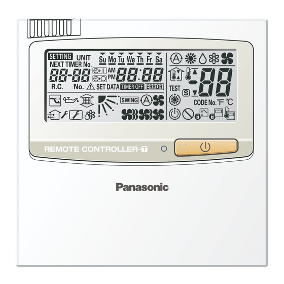
Timer remote controller (CZ-RTC2)
Basic remote controller ON/OFF
· Operation mode changeover (Cooling, Heating, Dry, Auto, Fan).
· Temperature setting (Cooling/Dry: 18-30 deg Heating: 16-30 deg).
· Fan speed setting H/ M/ L and Auto.
· Air flow direction adjustment.
Dimensions
H 120 x W 120 x D 16 mm
Time Function 24 hours real time clock
· Day of the week indicator.
Weekly Programme Function
· A maximum of 6 actions can be programmed for each day.
Outing Function
· This function can prevent the room temperature from dropping or rising
when the occupants are out for a long time.
Sleeping Function
· This function controls the room temperature for comfortable sleeping.
Max. 8 indoor units can be controlled from one remote controller
Remote control by main remote controller and sub controller is
possible
Max. 2 remote controllers (main remote controller and sub controller) can
be installed for one indoor unit.
Possible to connect to the outdoor unit using PAW-MRC cable for
servicing purposes
Advertisement
Table of Contents

Related Manuals for Panasonic CZ-RTC2


Summary of Contents for Panasonic CZ-RTC2
- Page 1 Timer remote controller (CZ-RTC2) Time Function 24 hours real time clock · Day of the week indicator. Weekly Programme Function · A maximum of 6 actions can be programmed for each day. Outing Function · This function can prevent the room temperature from dropping or rising when the occupants are out for a long time.
- Page 2 Control of 2WAY SYSTEM 3. Timer Remote Controller Timer Remote Controller/CZ-RTC2 How to Use the Timer Remote Controller Operating buttons Display 15 14 29 26 3-35...
-
Page 3: Names And Operations
Control of 2WAY SYSTEM 3. Timer Remote Controller Names and Operations Operation Section (Refer to the previous page) (Start/Stop) button (Ventilation) button Pushing this button starts, and pushing again stops the Use this button when you installed a fan available in the market. -
Page 4: Display Section
Control of 2WAY SYSTEM 3. Timer Remote Controller Display Section (Refer to the page 3-35) (Operation mode change control) indication (Setting) indication Displays when an operation mode is entered by the re- Appears when the timer program is being set. mote control unit, while another operation mode has been (Unit) indication already selected. -
Page 5: Setting The Present Time
Control of 2WAY SYSTEM 3. Timer Remote Controller Setting the Present Time Press and hold for more than 2 seconds to enter in the present day and time setting mode. Once you enter in the setting mode, , “ ”(day) and “time” fl ash. Set “... - Page 6 Control of 2WAY SYSTEM 3. Timer Remote Controller Weekly Program Function Checking Weekly Timer Set the weekly program assigning a given timer to each day of the week. Maximum of 6 programs a day and 42 programs a week can be set. Select the day and the TIMER number you want to program.
- Page 7 Control of 2WAY SYSTEM 3. Timer Remote Controller Changing the Program Timer To set the weekly program, follow the steps below. Select the program you want to set in the program confi rmation mode, and press . The enters the setting mode of the program currently displayed.
- Page 8 Control of 2WAY SYSTEM 3. Timer Remote Controller Weekly Program Function (Continued) Pattern 1 4. Set the program pattern. (program step 3) There are 4 program patterns. Pressing repeats the following display patterns. Pattern 2 Pattern 1 The indoor unit starts operation at the programmed time.
-
Page 9: Deleting/Invalidating Program Timer
Control of 2WAY SYSTEM 3. Timer Remote Controller Deleting the Program Timer To delete the program timer setting, follow the steps below. Press to enter the program confi rmation mode. Press to select the day of the program you want to de- lete. -
Page 10: Duplicating The Program Timer
Control of 2WAY SYSTEM 3. Timer Remote Controller Weekly Program Function (Continued) Duplicating the Program Timer You can duplicate the preset program by day. Select the copy source. is pressed in program checking mode , it enters the copy mode (Selecting the copy source ) of the pro- gram timer. -
Page 11: Outing Function
Control of 2WAY SYSTEM 3. Timer Remote Controller Outing Function Outing function is a function that prevents the room temperature from increasing too much (or decreasing too much) when no one is in the room. An air conditioner works automatically if this function is set effective. General Performance of the Outing Function COOL / DRY The air conditioner starts operation when the room temperature increases up to –1... - Page 12 Control of 2WAY SYSTEM 3. Timer Remote Controller Outing Function (Continued) Setting the Outing Function Press and hold for more than 2 seconds to display the upper limit temperature setting screen. and the upper limit temperature start fl ashing. (The default value of the upper limit temperature is 38 °C.) Press to select the upper limit temperature and press to fi...
-
Page 13: Sleeping Function
Control of 2WAY SYSTEM 3. Timer Remote Controller Sleeping Function This function leads you to a comfortable sleep and chang- When the off time comes: es the room temperature during your sleep. The indoor unit stops. You can set the off timer every one hour from 1 to 10 * The temperature returns to the setting at the time when hours. - Page 14 Control of 2WAY SYSTEM 3. Timer Remote Controller Sleeping Function (Continued) button does not work. Or if the operation does not start even if is pressed. Check the following table. Item Display of the remote control unit Contents (Lighting/flashing indication) The Error indication flashes The clock is not set.
-
Page 15: Installation
Control of 2WAY SYSTEM 3. Timer Remote Controller INSTALLATION MANUAL FOR TIMER REMOTE CONTROLLER Accessories for remote controller switch Remote controller Wood screws Wire joints Operation manual Installation manual (with 200mm wire) How to install the remote controller Do not supply power to the unit or try to operate it until the tubing and wiring to the outdoor unit is completed. - Page 16 Control of 2WAY SYSTEM 3. Timer Remote Controller Use 0.5mm - 1.25mm wires. Provided wire joint (white) Remote controller wiring can be extended to a maximum Remote controller wiring of 500m. (1) Strip the insulation to approximately 14 mm from the ends of the wires that will be connected.
- Page 17 Control of 2WAY SYSTEM 3. Timer Remote Controller Fig. 3-41 Fig. 3-42 Caution when installing the remote controller *1 Install the remote controller more than 95 mm apart from the wall surface. *2 To install the remote controllers side-by-side, keep the space between each for more than 125 mm. *3 To install the remote controllers one above the other, keep the space between each for more than 25 mm.
-
Page 18: Meaning Of Alarm Messages
Control of 2WAY SYSTEM 3. Timer Remote Controller Meaning of Alarm Messages Table of Self-Diagnostics Functions and Description of Alarm Displays Alarm Possible cause of malfunction message Error in receiving serial communication signal. Serial Remote controller is detecting (Signal from main indoor unit in case of group control) <E01>... - Page 19 Control of 2WAY SYSTEM 3. Timer Remote Controller Alarm Possible cause of malfunction message This alarm message shows when an indoor unit for multiple-use is not Serial Improper setting. connected to the outdoor unit. communication errors Duplication of main indoor unit address setting in group control. <L03>...
- Page 20 Control of 2WAY SYSTEM 3. Timer Remote Controller Alarm Possible cause of malfunction message EEPROM on indoor unit PCB failure Protective device Protective device for compressor EEPROM on the main or sub outdoor unit PCB has failed. for compressor is No.
Need help?
Do you have a question about the CZ-RTC2 and is the answer not in the manual?
Questions and answers
Not all rooms are getting warm air come through. Is there any function that shuts off zones ?