Table of Contents
Advertisement
Quick Links
Advertisement
Table of Contents

Related Manuals for dji Spreading WingsS800 EVO


Summary of Contents for dji Spreading WingsS800 EVO
- Page 1 Spreading Wings S800 EVO User Manual V 1.06 2013.10.14 Revision www.dji.com...
-
Page 2: Disclaimer
This product and manual are copyrighted by DJI Innovations with all rights reserved. No part of this product or manual shall be reproduced in any form without the prior written consent or authorization of DJI Innovations. No patent liability is assumed with respect to... -
Page 3: Profile
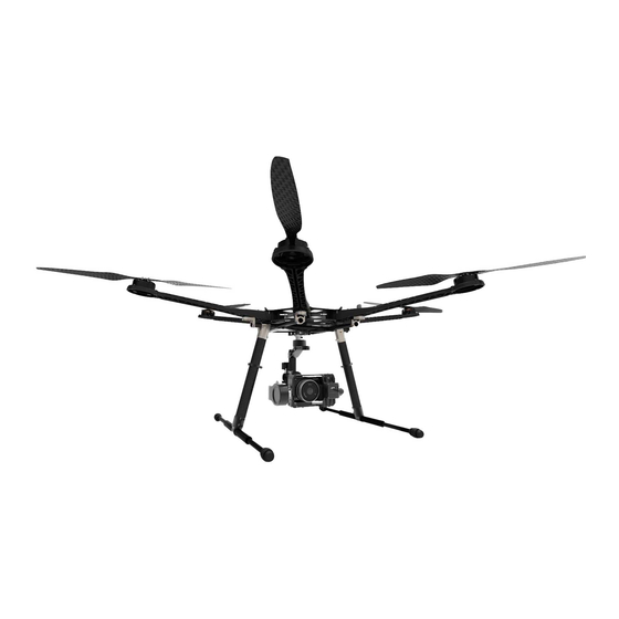
Profile S800 EVO is a multi-rotor designed for aerial photograph which integrates reinforced mechanical structures, stabilized dynamical system and high-efficiency power supply. Integrated designs make assembly and configuration become especially easy and fast; retractable landing gear, foldable propellers and collapsible GPS Mount are conveniently portable for optimal user experiences. -
Page 4: Table Of Contents
Contents Disclaimer ..........................................2 Profile ............................................3 Contents ..........................................4 Product Usage Cautions ....................................5 In The Box ..........................................6 Tools Needed ........................................6 Center Frame Wiring ......................................7 Attach Electric Equipment to Center Frame ............................. 8 Mount Frame Arms ......................................10 Mount Landing Gear ...................................... -
Page 5: Product Usage Cautions
Product Usage Cautions When flying, the fast rotating propellers may cause serious damage(s) and injuries. Therefore, please fly with a high safety in mind at all time. Assembly Cautions Mount the GPS Module with a bracket, to avoid interference with the power board of center frame. For IMU mounting, make sure the arrow direction marking on the IMU is pointing to the aircraft nose. -
Page 6: In The Box
In The Box Center Frame×1 Frame Arm×6 Retracting Mechanism×2 Landing Gear Support Tube ×2 Base Pipe×2 H Frame Connection Pipe×1、Spring×2 Package of 3-PIN Servo Cable ×1 Silicone Rubber Damper ×4 Package of Battery Tray×1 Package of IMU Mount×1 Screw Package for Frame×1 GPS Fixed Seat×1 Screw Package for Landing Gear×1 Out of The Box Guidance ×2... -
Page 7: Center Frame Wiring
Center Frame Wiring The top board is a power distribution board, and the bottom board is for loading autopilot system components. Top Board Slot Bottom Board Buckle Aircraft Nose Top Board Mark Motor counter clock-wise Mark Motor number XT60 Female To Gimbal ESC signal outlet Circuit line... -
Page 8: Attach Electric Equipment To Center Frame
Attach Electric Equipment to Center Frame (Fig.1)Remove the screws in the bottom board. (Fig.2)Attach the IMU module into IMU position in the center frame. Ensure the IMU casing is out of touching the top board edge, as vibration can cause IMU mal-function. (Fig.2)Please attach DJI Autopilot System parts onto the bottom board (not including GPS modules. - Page 9 Fig.3 Fix the screws Note: for DJI A2 user, please use the component in red; for WKM user, it is not required. Fig.4 Mount the GPS Fixed Seat and GPS module Mind You Fingers Fig.5 Note of folding the GPS Bracket...
-
Page 10: Mount Frame Arms
Notes: (1) Please add some lubricant at the position if it is hard to press down the buckle. (2) Slowly rotate the frame arm to prevent from breaking the copper contacts. ©2012 DJI Innovations. All Rights Reserved. - Page 11 (3) Please refer to to make sure the arm is perfectly positioned. (4) Make sure to use appropriate strength to press down the buckle correctly. (5) Do not hot plug arms. Tips: LED is on after motor start. Double Check Step 6 Arms①②are aircraft nose, arms④⑤...
-
Page 12: Mount Landing Gear
Mount Landing Gear By using a 2-position switch of R/C transmitter, you can control the landing gear to retract remotely. 1 Assembly & Connection The part with the control board attached is defined as left, and the other part is right. Make sure to make a distinction between the left and the right servos. -
Page 13: Travel Calibration
Assemble the left and right parts respectively, and then fix the screws at the joints with appropriate thread locker. Connect the left and right parts with connecting rod. For safety reasons, make sure to connect the springs to both parts. step3: Electrical Connections Plug the cables from the servos into the correct ports on the control board. -
Page 14: Transmitter Setting
Transmitter Setting Select a 2-position switch (default setting is OK) of Transmitter as the control input of the landing gear, and then make sure the corresponding port of receiver is connected to the [IN] port on control board. Retracted:Toggle the switch to Fig. -
Page 15: Led Indicator
Tips The system will turn off the servo power temporarily within 3 seconds after the landing gear has reached the target position. When powering on the system, if the Transmitter switch is at the [Retracted] position, which is the unsafe signal for the landing gear, the LED will quickly flash RED. -
Page 16: Mount Battery Bracket
Mount Battery Bracket Step1: Mount the retaining clip and the bracket, fix screws (but not tighten). M2.5X5 Bracket Notch Outwards Retaining Clips Chamfer Outwards Step2: Place the battery mounting board and adjust its position, and then tighten all screws. Battery Mounting Board Parallel Parallel Parallel... -
Page 17: Assembly
Assembly Assembly ② ③ ① ④ ⑥ ⑤ Align knob to mark Insert knob into arm Rotate knob Knob Mark Vibration Absorber Vibration Damper Mount Vibration Damper Mount Details Coaxial Align Coaxial Coaxial Align all knobs on H frame to the marks; refer to fig (1). Lie frame and Landing Gear horizontally, insert knobs into arms first, and then adjust to ③... -
Page 18: Install The Imu Mount (Optional)
Install the IMU Mount (Optional) If you wish to achieve a smooth and steady fight, carry out the following procedures to install the IMU Mount. (Fig.1) Remove the screws to dismount the Battery Bracket. (Fig.2) Fix the IMU Mount and remount the Battery Bracket. (Fig.3) Adjust the IMU Mount and the Battery Bracket, and then fix all the screws. -
Page 19: Appendix
Appendix ESC Sound ESC State Sound Ready ♪1234567--B--B Throttle stick is not at bottom BBBBBB… Input signal abnormal B--------B--------B… Input voltage abnormal BB---BB---BB---BB… ESC LED ESC State Standby Motor rotating Solid Red or Green On Motor rotating at full throttle position Solid Yellow On Tips: DJI ESCs are specially designed for multi-rotors. -
Page 20: Specifications
Specifications Frame Diagonal Wheelbase 800mm Frame Arm Length 350mm Frame Arm Weight 356g (with Motor, ESC, Propeller ) Center Frame Diameter 240mm Center Frame Weight 550g 460mm(Length)×425mm(Width)×320mm(Height) Landing Gear Size (Top width: 155mm) Retractable Landing Gear Weight 1050g (Including Battery Tray) Motor Stator Size 41×14mm... -
Page 21: Faq (Trouble Shooting)
FAQ (Trouble Shooting) Solder ESC Make sure to solder the thick wires and fine wires correctly, when solder ESC to frame arm. Clockwise and counter clockwise motor should be soldered to ESC correctly by different color order. For arms For arms Black Solder pad Blue... -
Page 22: Spare Parts Listing
Spare Parts Listing If S800 EVO needs component replaced, please refer to the following diagram to identify the component NO., and then make a purchase of corresponding package. Each package includes screws needed. The Components Number is defined as bellow. ;... - Page 23 Center Frame M2x9(12pcs) SE021401(6pcs) M2.5x5(25pcs) SE021201 SE021601(7pcs) SE021501 SE021502 SE021503 SE021301 SE021301 M2.5x5(25pcs) Package NO. Name Components Number Center Frame SE021201、SE021301、SE021401、SE021501、 SE021502 、SE021503、SE021601、M2x9、M2.5x5 Center Frame Top Board SE021201、M2x9、M2.5x5 Center Frame Bottom Board SE021301、M2.5x5 Top Board Cover SE021401、M2x9 Arm Mounting Bracket SE021501、SE021502、SE021503、...
- Page 24 Landing Gear SE032802 SE031801 SE032901 SE033301 SE031901 SE032204 M2.5x5 2pcs SE033102 SE032803 SE032801 SE032801 SE032803 M3x8( 4pcs SE033001 SE032802 M3x5 2pcs SE032804 HC_M3x8( 2pcs SE033103 M2 5x5 4pcs SE033104 SE032201 SE032202 HC_M2 5x10 4pcs SE032101 SE031701 SE032001 SE032401 SE031702 SE032301 SE032402 SE033201 M3x8...
- Page 25 Base Tube SE032601、SE032701 Silicone Rubber Damper SE032701 Damping Unit (Set) SE032801、SE032802、SE032803、SE032804、HC_M3x8 Aluminum Tube of H-Frame SE032901 Silicone Rubber of H-Frame SE033001 Battery Tray SE033101、 SE033102、 SE033103、 SE033104、 M2.5x5、 M3x5 Control arm of Retractable SE033201、SE033202、SE033203、M2.5x8 Module(Left) Control Arm of Retractable SE033301、SE033202、SE033203、M2.5x8 Module(Right) Shaft Sleeve...
- Page 26 Package NO. Name Components Number Vibration absorber of Motor SE014401、SE014402、M2.5...
Need help?
Do you have a question about the Spreading WingsS800 EVO and is the answer not in the manual?
Questions and answers