Table of Contents
Advertisement
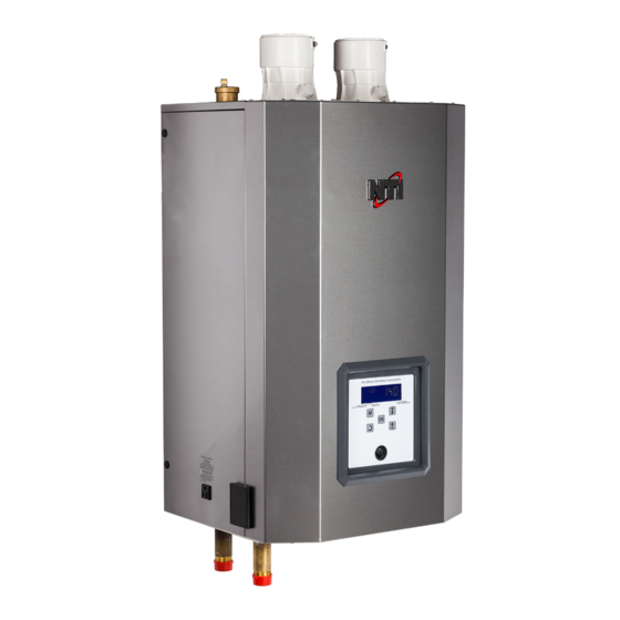
Trinity Tx
Model Numbers: Tx 51 - 200
Version Date: 2019-06-20
INSTALLATION AND OPERATION MANUAL
TABLE OF CONTENTS
1.0
INTRODUCTION ................................................................................................................ 3
2.0
SPECIFICATIONS .............................................................................................................. 6
3.0
BOILER LOCATION .......................................................................................................... 7
4.0
GENERAL VENTING ....................................................................................................... 10
5.0
VENT/AIR-INLET TERMINATION CLEARANCES ..................................................... 24
6.0
CONDENSATE DRAIN .................................................................................................... 26
7.0
INSTALLING GAS PIPING .............................................................................................. 28
8.0
LIGHTING THE BOILER ................................................................................................. 30
9.0
GAS VALVE AND BURNER SET-UP ............................................................................ 33
10.0 BOILER AND HEATING SYSTEM PIPING ................................................................... 36
11.0 DOMESTIC HOT WATER (DHW) PIPING - TX151C & TX200C (COMBI) ............... 47
12.0 FIELD WIRING ................................................................................................................. 49
13.0 CASCADE INSTRUCTIONS ............................................................................................ 52
14.0 WIRING SCHEMATICS ................................................................................................... 54
15.0 INSTALLATION CHECKLIST ........................................................................................ 56
16.0 ANNUAL MAINTENANCE AND INSPECTION ........................................................... 57
17.0 DISPLAY MENU GUIDE ................................................................................................. 59
18.0 TROUBLESHOOTING ..................................................................................................... 72
19.0 PARTS LIST ...................................................................................................................... 75
HAZARD SYMBOLS AND DEFINITIONS
Danger Sign: Indicates a hazardous situation which, if not avoided, will
result in serious injury or death.
Warning Sign: Indicates a hazardous situation which, if not avoided,
could result in serious injury or death.
Caution Sign plus Safety Alert Symbol: Indicates a hazardous situation
which, if not avoided, could result in minor or moderate injury.
Caution Sign without Safety Alert Symbol: Indicates a hazardous
situation which, if not avoided, could result in property damage.
Notice Sign: Indicates a hazardous situation which, if not avoided,
could result in property damage.
unit may result in property damage, serious injury to occupants, or possibly death.
This Boiler must be installed by a licensed and trained Heating
Technician or the Warranty is Void. Failure to properly install this
H
Visit us
online
NTI # 84874
Advertisement
Table of Contents

Related Manuals for NTI Trinity Tx151


Summarization of Contents
HAZARD SYMBOLS AND DEFINITIONS
Danger Sign Definition
Defines the "DANGER" symbol and its meaning, indicating a hazardous situation.
Warning Sign Definition
Defines the "WARNING" symbol and its meaning, indicating a hazardous situation.
Caution Sign Definition
Defines the "CAUTION" symbols and their meanings, indicating hazardous situations.
1.0 INTRODUCTION
General Installation Requirements
Outlines installation compliance with codes and manual requirements.
User and Installer Responsibilities
Details owner's duties for maintenance and installer's duties for proper installation.
LP Propane and Venting Information
Liquefied Petroleum (LP) Propane Operation Cautions
Provides attention points for operating with LP propane gas.
Exhaust Vent/Air-Inlet Piping Basics
Introduces requirements for exhaust and air-inlet piping systems.
2.0 SPECIFICATIONS
High Altitude Operation and Capacity De-rating
Explains how to de-rate boiler capacity for high altitude installations.
3.0 BOILER LOCATION
Boiler Area Ventilation Requirements
Specifies minimum ventilation air openings for the boiler area.
Closet, Alcove, and Garage Installation Clearances
Details clearances for various installation types including garages.
4.0 GENERAL VENTING
Removing Boiler from Common Venting System
Details procedures and safety for removing a boiler from a common vent.
Venting Procedures and Piping
Mandatory Pre-commissioning for Plastic Venting
Outlines the mandatory pre-commissioning steps for PVC/CPVC venting.
Near Boiler Vent/Air-inlet Piping Connection
Discusses universal adapters and pipe connection methods.
5.0 VENT/AIR-INLET TERMINATION CLEARANCES
Termination Clearances Quick Reference Table
Provides a table of minimum clearances for various termination points.
6.0 CONDENSATE DRAIN
Condensate Trap Installation Instructions
Step-by-step guide for installing the condensate trap.
7.0 INSTALLING GAS PIPING
Gas Piping Installation Requirements and LP Conversion
Details requirements for gas piping and LP conversion.
8.0 LIGHTING THE BOILER
Safety Before Operating and Operating Instructions
Crucial safety information and step-by-step guide for starting and operating.
Boiler Start-Up Procedures
Initial Start-Up and Re-lighting Procedures
Describes initial start-up and re-lighting processes.
9.0 GAS VALVE AND BURNER SET-UP
Combustion Calibration and Adjustments
Mandated procedure for calibrating burner combustion and adjustments.
Gas Line Pressure Test and Parameters
Line Pressure and Combustion Data Table
Lists required gas line pressures and combustion parameters.
10.0 BOILER AND HEATING SYSTEM PIPING
System Preparation and Water Quality Requirements
Covers system preparation, cleaning, and water chemistry requirements.
Boiler Water Treatment and Plumbing
Near Boiler Plumbing and LWCO Installation
Details plumbing components and LWCO installation.
Boiler System Plumbing Configurations
Flow Rates, Pumps, and Component Requirements
Specifies minimum flow rates, pump sizing, and essential components.
System Plumbing Components and Strategies
Air Removal and Expansion Tank Strategy
Explains air removal importance and expansion tank placement.
Plumbing Configuration Examples
Circulator Configuration Examples
Illustrates single/multi circulator setups for various models.
11.0 DOMESTIC HOT WATER (DHW) PIPING
DHW Operation and Preheat Mode Functionality
Explains how Combi models heat DHW and the preheat feature.
DHW Plumbing Details
DHW Plumbing Components Installation
Describes installation of Y-strainer, check valve, and throttling valve.
12.0 FIELD WIRING
Wiring Connections and Fuse Protection Overview
Explains wiring connections and fuse locations.
Field Connections Table
Table 12-1 Field Connections Description
Lists all field connection points and their descriptions.
13.0 CASCADE INSTRUCTIONS
Establishing Cascade System Operation
Details communication wiring and managing boiler setup.
Cascade Plumbing and Pump Control Logic
Explains cascade plumbing and pump control.
Cascade System Sensors and Settings
Cascade System Sensors and Boiler Addressing
Describes sensor wiring and boiler address assignment.
14.0 WIRING SCHEMATICS
Tx Connection Diagram Overview
Provides a detailed connection diagram for the boiler.
Tx Ladder-Logic Diagram
Ladder-Logic Diagram Navigation and Legend
Explains the ladder-logic diagram and its symbols.
15.0 INSTALLATION CHECKLIST
Installation, Start-up, and Operational Checks
Comprehensive checklists for installation and initial operation.
Contractor Guidance and Warnings
Guidance for contractors, including documentation and warnings.
16.0 ANNUAL MAINTENANCE AND INSPECTION
Annual Inspection and Combustion Chamber Cleaning
Covers annual inspection checklist and combustion chamber cleaning.
RFC Safety Precautions
PPE and Handling Instructions for Refractory Ceramic Fibers
Recommends PPE and handling instructions for RFC.
Crystalline Silica Hazards and Handling Guidelines
Warns about crystalline silica and provides handling guidelines.
17.0 DISPLAY MENU GUIDE
Boiler Start-up and Main Screen Display
Describes initial power-up, de-air sequence, and main screen.
User and Installer Menu Access Procedures
Explains how to access and navigate the user and installer menus.
Installer Menu Operations
Installer Menu Navigation and Settings Adjustment
Explains how to access and adjust installer menu settings.
Lockout and Error Code Descriptions
Ignition, Gas Valve, and Sensor Error Codes
Lists and describes common error codes related to ignition, gas, and sensors.
18.0 TROUBLESHOOTING
Servicing Safety Precautions
Essential safety rules to follow when servicing the boiler.
Diagnosing Inoperative Boiler and Operation Issues
Troubleshooting steps for common boiler failures.
Controller Replacement Instructions
Appliance Type Setting and Replacement Procedure
Explains how to set the appliance type for a replacement controller.
19.0 PARTS LIST
Illustrated Parts Breakdown Diagrams
Provides diagrams of boiler components and their parts.
Parts List - Tx Series
Table 19-1 Parts List (Items 1-23)
Lists parts from item 1 through 23 with descriptions.
Parts List - Tx Series (Continued)
Table 19-1 Parts List (Items 23-75)
Lists parts from item 23 through 75 with descriptions.
Parts List - Tx Series (Continued)
Table 19-1 Parts List (Items 75-119)
Lists parts from item 75 through 119 with descriptions.
Need help?
Do you have a question about the Trinity Tx151 and is the answer not in the manual?
Questions and answers