
Subscribe to Our Youtube Channel
Related Manuals for Fujitsu PRIMERGY TX1320 M1


Summary of Contents for Fujitsu PRIMERGY TX1320 M1
- Page 1 Operating Manual - English FUJITSU Server PRIMERGY TX1320 M1 Operating Manual Edition July 2014...
-
Page 2: Copyright And Trademarks
– The contents of this manual may be revised without prior notice. – Fujitsu assumes no liability for damages to third party copyrights or other rights arising from the use of any information in this manual. – No part of this manual may be reproduced in any form without the prior written permission of Fujitsu. - Page 3 Before reading this manual For your safety This manual contains important information for safely and correctly using this product. Carefully read the manual before using this product. Pay particular attention to the accompanying manual "Safety Notes and Regulations" and ensure these safety notes are understood before using the product.
- Page 4 Please consult the sales staff of Fujitsu if intending to use this product for high safety use. Measures against momentary voltage drop This product may be affected by a momentary voltage drop in the power supply caused by lightning.
- Page 5 Only for the Japanese market: Shielded LAN cables should be used in this product. Although described in this manual, some sections do not apply to the Japanese market. These options and routines include: – CSS (Customer Self Service) Operating Manual TX1320 M1...
- Page 6 Operating Manual TX1320 M1...
-
Page 7: Table Of Contents
Contents Introduction ......11 Concept and target groups for this manual ..12 Documentation overview . - Page 8 Contents Notes on connecting/disconnecting cables ..56 Starting up and operation ....59 Opening the drive cover .
- Page 9 Contents No screen display or display drifts ....83 No mouse pointer displayed on screen ... . 83 Incorrect date and time .
- Page 10 Contents Operating Manual TX1320 M1...
-
Page 11: Introduction
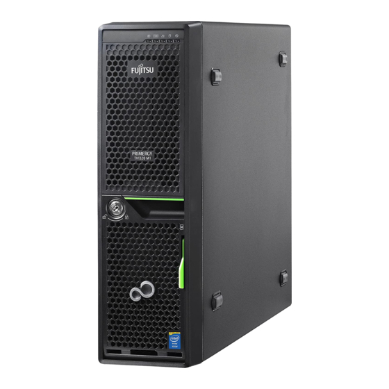
Introduction The PRIMERGY TX1320 M1 server is an Intel-based server for small and medium-sized networks and can be used in the horizontal position or as a desktop model. The PRIMERGY TX1320 M1 server features exceptionally low energy consumption, very quiet running and a compact size. As a result, it is also the ideal solution for small offices. -
Page 12: Concept And Target Groups For This Manual
Documentation overview More information on your PRIMERGY TX1320 M1 can be found in the following documents: – "Quick Start Hardware - FUJITSU Server PRIMERGY TX1320 M1"... -
Page 13: Notational Conventions
Introduction All documentation on PRIMERGY hardware and ServerView software is available online from the Fujitsu manuals server at: – For the global market http://manuals.ts.fujitsu.com – For the Japanese market: http://jp.fujitsu.com/platform/server/primergy/manual The complete PRIMERGY documentation set can also be downloaded as a DVD ISO image at: –... - Page 14 Introduction Operating Manual TX1320 M1...
-
Page 15: Functional Overview
– Memory modules – System fans – Expansion cards For information on replacing these components, see the "FUJITSU Server PRIMERGY TX1320 M1 Upgrade and Maintenance Manual". CSS indicators on the control panel and on the back of the PRIMERGY server provide you with information if a CSS event arises. - Page 16 (for the Japanese market) System board The features of the system board are described in the "FUJITSU Server PRIMERGY TX1320 M1 Upgrade and Maintenance Manual" and in the "D3239 BIOS Setup Utility for FUJITSU Server PRIMERGY TX1320 M1 Reference Manual"...
- Page 17 Functional overview Hard disk drives The server is shipped with one of the following drive cages: – For up to two non hot-plug 3.5-inch SATA hard disk drives: Up to two 3.5-inch SATA HDD modules can be used in the drive cage. Each HDD module can accommodate an SATA hard disk drive with a maximum height of 1 inch.
- Page 18 "Configuring the server" on page Further information on SAS/SATA RAID controllers is provided in the "Modular RAID Controller Installation Guide" (on the Fujitsu manuals server under x86 Servers - Storage Adapters - LSI RAID / SCSI Controllers). Further information on other SAS/SATA RAID controllers (e.g. for...
- Page 19 "hides" the defective system components. The PDA (Prefailure Detection and Analysis) technology from Fujitsu analyzes and monitors all components that are critical for system reliability. A RAID controller supports different RAID levels and increase the availability and data security of the system.
- Page 20 Functional overview iRMC S4 with integrated management LAN connector The iRMC S4 (integrated Remote Management Controller) is a Baseboard Management Controller (BMC) with integrated management LAN connector and expanded functionality that was previously only available with additional plug-in cards. In this way, the iRMC S4 enables complete control of PRIMERGY servers, regardless of system status, and thus particularly the control of PRIMERGY servers that are in the "out-of-band"...
- Page 21 Server management is implemented using the ServerView Operations Manager supplied and the PDA (Prefailure Detection and Analysis) technology from Fujitsu. PDA reports the threat of a system error or overload at an early stage, allowing preventive measures to be taken.
- Page 22 BIOS update. With the iRMC (integrated Remote Management Controller) on the system board, the PRIMERGY TX1320 M1 server can also be maintained and serviced remotely. This enables remote diagnosis for system analysis, remote configuration and remote restart should the operating system or hardware fail.
- Page 23 ServerView Remote Management ServerView Remote Management is the remote management solution from Fujitsu for PRIMERGY servers. ServerView Remote Management and the relevant hardware components integrated on the system board allow remote monitoring and maintenance as well as fast restoration of operation in the event of errors.
-
Page 24: Server Specification
Functional overview Server specification This section explains the specifications for the server. The specifications for this server are liable to be updated without any notice. Please be forewarned. System Board System board type D3239 ® Chipset Intel C224 Processor ® ®... - Page 25 Functional overview Service LAN (RJ45) 1 x dedicated service LAN port for iRMC S4 (10/100/1000 Mbit/s) Service LAN traffic can be switched to shared onboard Gbit LAN port Onboard or integrated controllers RAID Controller Modular RAID 0/1 controller with "Integrated Mirroring Enhanced"...
- Page 26 Functional overview Drive bays Hard disk bay 6x 2.5-inch hot-plug SAS/SATA or 2x 3.5-inch non configuration hot-plug SATA Accessible drive bays 1x 3.5/1.6-inch for backup devices; 1x 5.25/0.5-inch for CD-RW/DVD Notes accessible drives all possible options described in relevant system configurator Operating Panel Operating buttons...
- Page 27 Functional overview Dimensions / Weight Upright operating 180 mm x 343 mm x 360 mm (including feet) position (W x D x H) Horizontal operating 340 mm x 343 mm x 98 mm position (W x D x H) Weight up to 10 kg Weight notes Weight may vary depending on actual configuration...
- Page 28 Functional overview Noise level (depending on the configuration) SATA systems SAS systems Sound power level L 3.7 B (standby) 4.9 B (standby) (ISO 9296) 3.7 B (operation) 5.0 B (operation) Sound pressure level at 22 dB (A) (standby) 33 dB (A) (standby) adjacent workstation 23 dB (A) (operation) 35 dB (A) (operation)
- Page 29 Functional overview Compliance with regulations and standards Product safety and ergonomics International IEC 60950-1 2ed; am1 Europe Safety EN 60950-1 2ed.; am1 EN 62479 EN 62311 Ergonomics ISO 9241-3 EN 2941-3 EK1-ITB2000:2013 USA / Canada CSA-C22.2 No. 60950-1-07 2ed. UL 60950-1 2ed. Taiwan CNS 14336 China...
- Page 30 Functional overview Operating Manual TX1320 M1...
-
Page 31: Installation Steps, Overview
Details on how to operate the ServerView Installation Manager, as well as some additional information, are included in the "ServerView Suite Installation Manager" user’s guide (on the Fujitsu manuals server under x86 Servers - Software - ServerView Suite - Server Installation and Deployment). - Page 32 You will find more information on installing the server remotely or locally in the "ServerView Suite Installation Manager" user’s guide (on the Fujitsu manuals server under x86 Servers - Software - ServerView Suite - Server Installation and Deployment). Operating Manual...
-
Page 33: Important Information
Important information In this chapter you will find essential information regarding safety when working on your server. Safety instructions The following safety instructions are also provided in the manual "Safety Notes and Regulations" or " 安全上のご注意 ". This device meets the relevant safety regulations for IT equipment. If you have any questions about whether you can install the server in the intended environment, please contact your sales outlet or our customer service team. - Page 34 Important information Before starting up CAUTION! During installation and before operating the device, observe the ● instructions on environmental conditions for your device (see "Ambient conditions" on page 27). If the server has been moved from a cold environment, condensation ●...
- Page 35 Important information CAUTION! Ensure that the power sockets on the device and the grounded power ● outlets are freely accessible. The On/Off button or the main power switch (if present) does not ● isolate the device from the mains power supply. To disconnect it completely from the mains power supply, unplug all network power plugs from the grounded power outlets.
- Page 36 Important information CAUTION! Proper operation of the system (in accordance with ● IEC 60950-1/EN 60950-1) is only ensured if the casing is completely assembled and the rear covers for the installation slots have been fitted (electric shock, cooling, fire protection, interference suppression).
- Page 37 ● concerning special waste. Replace the lithium battery on the system board in accordance with ● the instructions in the FUJITSU Server PRIMERGY TX1320 M1 Upgrade and Maintenance manual. All batteries containing pollutants are marked with a symbol (a ●...
- Page 38 Important information Working with CDs/DVDs/BDs and optical drives When working with devices with optical drives, these instructions must be followed. CAUTION! Only use CDs/DVDs/BDs that are in perfect condition, in order to ● prevent data loss, equipment damage and injury. Check each CD/DVD/BD for damage, cracks, breakages etc.
- Page 39 Important information Do not contaminate the CD/DVD/BD surface with fingerprints, oil, ● dust, etc. If dirty, clean with a soft, dry cloth, wiping from the center to the edge. Do not use benzene, thinners, water, record sprays, antistatic agents, or silicone-impregnated cloth. Be careful not to damage the CD/DVD/BD surface.
- Page 40 Important information Modules with Electrostatic-Sensitive Devices Modules with electrostatic-sensitive devices are identified by the following sticker: Figure 1: ESD label When you handle components fitted with ESDs, you must always observe the following points: Switch off the system and remove the power plugs from the power outlets ●...
-
Page 41: Ce Conformity
Important information Other important information: During cleaning, observe the instructions in section "Cleaning the server" on ● page Keep this operating manual and the other documentation (such as the ● technical manual, documentation DVD) close to the device. All documentation must be included if the equipment is passed on to a third party. -
Page 42: Fcc Class A Compliance Statement
Consult the dealer or an experienced radio/TV technician for help. ● Fujitsu is not responsible for any radio or television interference caused by unauthorized modifications of this equipment or the substitution or attachment of connecting cables and equipment other than those specified by Fujitsu. The correction of interferences caused by such unauthorized modification, substitution or attachment will be the responsibility of the user. -
Page 43: Transporting The Server
If you need to lift or transport the server, ask other people to help you. Environmental protection Environmentally-friendly product design and development This product has been designed in accordance with the Fujitsu standard for "environmentally friendly product design and development". This means that key factors such as durability, selection and labeling of materials, emissions, packaging, ease of dismantling and recycling have been taken into account. - Page 44 Details regarding the return and recycling of devices and consumables within Europe can also be found in the "Returning used devices" manual, via your local Fujitsu branch or from our recycling center in Paderborn: Fujitsu Technology Solutions Recycling Center D-33106 Paderborn Tel.
-
Page 45: Hardware Installation
Hardware installation CAUTION! Follow the safety instructions in the chapter "Important information" ● on page Do not expose the server to extreme environmental conditions (see ● "Ambient conditions" on page 27). Protect the server from dust, humidity and heat. Make sure that the server is acclimatized for the time indicated in this ●... -
Page 46: Unpacking The Server
Hardware installation Unpacking the server CAUTION! Follow the safety instructions in "Important information" on page The server must always be lifted or carried by at least two people. (For the Japanese market, please refer to " 安全上のご注意 ".) Do not unpack the server until it is at its installation location. Ê... -
Page 47: Setting Up The Server
Hardware installation Setting up the server Ê Set up the server. Note that the server may be operated in the vertical (see section "Positioning the server vertically" on page 48) or horizontal position (see section "Positioning the server horizontally" on page 51). -
Page 48: Positioning The Server Vertically
Hardware installation 5.2.1 Positioning the server vertically CAUTION! If the server is positioned vertically, the stabilizers must be attached! The stabilizers must be attached in the correct direction (see figure 4 on page 50). Clipping the stabilizers together Figure 2: Clipping the stabilizer together Ê... - Page 49 Hardware installation Adjusting the width of the stabilizers Figure 3: Adjusting the width of a stabilizer You may have to adjust the width of the stabilizers. Ê Press the two locking levers (1) and keep them pressed. Ê Pull the stabilizer apart (2). Operating Manual TX1320 M1...
- Page 50 Hardware installation Placing the server on the stabilizers Figure 4: Placing the server on stabilizers Ê Place the server on the stabilizers (1). Position the stabilizers between the rubber feet (2). Ê Press the stabilizers together (3). Operating Manual TX1320 M1...
-
Page 51: Positioning The Server Horizontally
Hardware installation 5.2.2 Positioning the server horizontally CAUTION! If the server is positioned horizontally, ensure that the rubber feet are pointing downward. Figure 5: Positioning the server horizontally Ê Place the server on its four rubber feet. Operating Manual TX1320 M1... - Page 52 Hardware installation Figure 6: Rotating the Fujitsu Infinity Mark Ê Rotate the Fujitsu Infinity Mark clockwise by 90 degrees. Operating Manual TX1320 M1...
-
Page 53: Connecting Devices To The Server
Hardware installation Connecting devices to the server The connectors for external devices are on the front and rear of the server. The additional connectors available on your server depend on the expansion cards installed. The standard connectors are indicated by symbols and color coding: Figure 7: Connector panel on the rear side 1 Management LAN connector, for iRMC S4 server management function 2 Shared LAN connector (LAN1) -
Page 54: Connecting The Server To The Mains
Hardware installation Connecting the server to the mains The server is fitted with a built-in power supply. CAUTION! The server is automatically set to a mains voltage in the range 100V - 240V. You may only operate the server if its rated voltage range corresponds to the local mains voltage. - Page 55 Hardware installation Figure 8: Using cable ties Ê Thread the cable tie through the eye (1). Ê Pull the cable tie tight to secure the power cable. The insulated connector cannot now be disconnected from the server accidentally. You can loosen the cable tie by opening the small locking lever (2). Operating Manual TX1320 M1...
-
Page 56: Notes On Connecting/Disconnecting Cables
Hardware installation Notes on connecting/disconnecting cables CAUTION! Always read the documentation supplied with the device you wish to connect. Never connect, or disconnect cables during a thunderstorm. Never pull on a cable when disconnecting it. Always take hold of the cable by the plug. - Page 57 Hardware installation Information for ensuring electromagnetic compatibility All data and signal cables must have sufficient shielding. The use of cable type S/FTP Cat5 or higher is recommended. Use of unshielded or badly shielded cables may lead to increased emission of interference and/or reduced fault-tolerance of the device.
- Page 58 Hardware installation Operating Manual TX1320 M1...
-
Page 59: Starting Up And Operation
Starting up and operation CAUTION! Follow the safety instructions in chapter "Important information" on page Opening the drive cover Opening the drive cover with locked key Figure 9: Opening the drive cover with locked key Ê Rotate the green hook (1) in the drive cover for 90°. As a result, even if the key is locked, the drive cover can be removed. - Page 60 Starting up and operation Figure 10: Opening the drive cover Ê Turn the key clockwise (1) and remove the key. Ê Open the drive cover carefully in the direction of the arrow (2) until the ratches of the cover are released, and pull it downward to remove it (3). CAUTION! Do not pull too hard to avoid damage to the locking mechanism.
- Page 61 Starting up and operation Figure 11: Removing the drive cover from the HDD cover Ê Carefully pull out on the green release lever (1) and lift off the drive cover (2). Operating Manual TX1320 M1...
-
Page 62: Opening The Hdd Cover
Starting up and operation Opening the HDD cover Figure 12: Removing the HDD cover Ê Unlock the server (1). Ê Remove the HDD cover (2). The HDD cover is replaced and the server locked in the reverse order. Operating Manual TX1320 M1... -
Page 63: Controls And Indicators
Starting up and operation Controls and indicators 6.3.1 Front of server Figure 13: Front side (indicators and controls) 1 HDD error indicator 9 Global Error indicator 2 PSU error indicator 10 HDD / SSD activity indicator 3 Temperature error indicator 11 Power-on indicator 4 CPU error indicator 12 On/Off button... -
Page 64: Local Diagnostic Indicators
Starting up and operation 6.3.1.1 Local diagnostic indicators Symbol Indicator Status Description HDD / SSD, SAS / SATA HDD / SSD orange on backplane or RAID controller [HDD]] error indicator failure detected Hot-plug PSU module failure detected PSU error orange on [PSU] indicator Only available in redundant... -
Page 65: Control Elements
Starting up and operation 6.3.1.2 Control elements Symbol Button Function This button is used to switch the server on or off. If the system is running an ACPI-compliant On / Off button operating system, the pressing the On / Off button will performs a graceful shutdown. -
Page 66: Indicators On The Control Panel
Starting up and operation 6.3.1.3 Indicators on the control panel Symbol Indicator Status Description green on Server is switched on and running. Server is switched off, but mains voltage is present (standby mode). After connecting the server orange on to the mains, it will take about 60 seconds until the server will switch into standby mode. -
Page 67: Id Card
Starting up and operation Symbol Indicator Status Description No critical event (non CSS component) Global error Prefailure detected (non CSS orange on indicator component) orange Non-CSS component failure flashing No critical event (CSS component) Prefailure detected (CSS yellow on CSS indicator component) [CSS] yellow... -
Page 68: Indicators On The Drives
Starting up and operation You can pull out the ID card as far as it will go and push it back again. The ID card contains various system information, such as the product name, serial number, order number, MAC addresses and DNS name (in the Japanese market, only the product name and the serial number). - Page 69 Starting up and operation 2 HDD FAULT (orange) (in conjunction with a RAID controller) SAS server variant ● – Does not light: no HDD error – Lit: HDD Faulty (drive defective/needs replacing, drive failed, drive deactivated by software or the HDDmodule is not correctly inserted) –...
-
Page 70: Rear Of The Server
Starting up and operation 6.3.2 Rear of the server CSS, Global Error and ID indicators Figure 16: Indicators on the connector panel: CSS, Global Error and ID indicators 1 CSS, Global Error and ID indicators (yellow, orange and blue) Global Error indicator (orange) –... - Page 71 If the event is still acute after a power failure, the indicator is activated after the restart. The indicator also lights up in standby mode. For more information on the CSS concept, see the FUJITSU Server PRIMERGY TX1320 M1 Upgrade and Maintenance manual. blue on...
- Page 72 Depending on the settings in the BIOS, the shared LAN connector may also be used as a service LAN connector. You will find further information in the "D3239 BIOS Setup Utility for FUJITSU Server PRIMERGY TX1320 M1" manual. Operating Manual...
-
Page 73: Switching The Server On And Off
Starting up and operation Switching the server on and off CAUTION! If nothing appears on the screen but flickering stripes after switching on the server, switch the server off immediately (see section "Flickering stripes on monitor screen" on page 83). The On/Off button does not disconnect the server from the mains. - Page 74 Starting up and operation If the operating system does not switch the server off automatically, press the On/Off button for at least four seconds and/or send a corresponding control signal. Other On/Off options Besides the On/Off button, the server can be switched ON and OFF in the following ways: –...
-
Page 75: Configuring The Server
A separate utility is available to the controller for MegaRAID configuration. For further information, refer to the "SAS Software User’s Guide" (on the Fujitsu manuals server under x86 Servers - Expansion Cards - Storage Adapters - LSI Configuration Software). Further information on modular RAID controllers is provided in the "Modular RAID Controller Installation Guide"... -
Page 76: Configuring The Server And Installing The Operating System With The Serverview Installation Manager
Starting up and operation Descriptions of operating systems not covered in the controller manual are provided in the corresponding readme under: http://www.fujitsu.com/global/services/computing/server/ia/driver/index.html (for the EMEA market). http://jp.fujitsu.com/platform/server/primergy/downloads/ (for the Japanese market). 6.5.3 Configuring the server and installing the operating system with the ServerView Installation Manager... -
Page 77: Configuring The Server And Installing The Operating System Without The Serverview Installation Manager
Starting up and operation If you are using the ServerView Installation Manager, you can skip the following section on how to configure the server and install the operating system. Continue from section "Cleaning the server" on page 6.5.4 Configuring the server and installing the operating system without the ServerView Installation Manager Configuring the onboard SATA controller... -
Page 78: Cleaning The Server
Starting up and operation Cleaning the server CAUTION! Switch off the server and disconnect the power plugs from the properly grounded power outlets. Do not clean any interior parts yourself; leave this job to a service technician. Do not use any cleaning agents that contain abrasives or may corrode plastic. -
Page 79: Property And Data Protection
BIOS from being overwritten. By combining these options you can achieve optimum protection for your system. A detailed description of the Security menu and how to assign passwords can be found in the BIOS Setup documentation on the Fujitsu manuals server. Operating Manual... - Page 80 Property and data protection Operating Manual TX1320 M1...
-
Page 81: Troubleshooting And Tips
Troubleshooting and tips CAUTION! Follow the safety instructions in the “Safety Notes and Regulations” manual and in chapter "Hardware installation" on page If a fault occurs, attempt to resolve it using the measures described: – in this chapter, – in the documentation for the connected devices, –... -
Page 82: Server Switches Itself Off
Troubleshooting and tips Server switches itself off Server Management has detected an error Ê Check the error list of System Event Log in ServerView Operations Manager or in the iRMC web interface, and attempt to eliminate the error. Screen remains blank Monitor is switched off Ê... -
Page 83: Flickering Stripes On Monitor Screen
Troubleshooting and tips Flickering stripes on monitor screen CAUTION! Switch off the server immediately. Risk of damaging the server. Monitor does not support the set horizontal frequency Ê Find out which horizontal frequency your monitor screen supports. You will find the horizontal frequency (also known as line frequency or horizontal deflection frequency) in the documentation for your monitor. -
Page 84: Incorrect Date And Time
If the date and time are still wrong after the server has been switched off and back on again, replace the lithium battery (for a description refer to the "FUJITSU Server PRIMERGY TX1320 M1 Upgrade and Maintenance Manual") or contact our customer service team. -
Page 85: Error Message On Screen
Troubleshooting and tips 8.10 Error message on screen The meaning of the error message is explained in the documentation for the relevant components and programs on the Fujitsu manuals server. Operating Manual TX1320 M1... - Page 86 Troubleshooting and tips Operating Manual TX1320 M1...
Need help?
Do you have a question about the PRIMERGY TX1320 M1 and is the answer not in the manual?
Questions and answers