Table of Contents
Advertisement
Quick Links
Ramsey Electronics Model No.
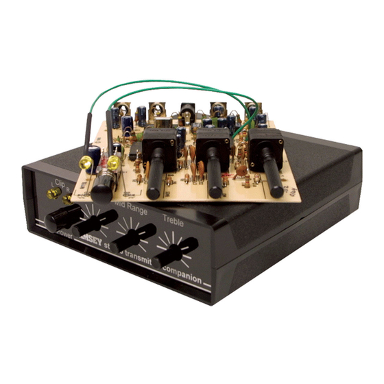
Now you can give your home stereo transmitter all of the features
found in a professional radio station! Control and prevent
overmodulation, interference from high frequency signals such as
TVs and older CD players, and "sweeten" the mix with Bass,
Presence, and Brilliance. A perfect companion for the FM10A and
the FM25 or any other FM radio transmitter!
•
Gives your station that professional sound with real "Punch!"
•
Ideal companion for FM10A and FM25
•
Requires any DC voltage from 9 to 12VDC
•
Uses line levels from CD players, tape decks, mixers etc.
•
Bass, Presence, and Brilliance controls
•
Dynamic range limiter to prevent overmodulation.
•
15kHz 8th order butterworth low pass filters on each output to
prevent high frequency interference with the stereo carrier.
•
Clear, concise assembly instructions lead you to a finished product
that works FIRST time!
•
Add our case and knob set for a finished 'Pro' look. Cases match all
Ramsey products.
STC1
Advertisement
Table of Contents

Subscribe to Our Youtube Channel
Related Manuals for Ramsey Electronics STC1


Summary of Contents for Ramsey Electronics STC1
- Page 1 Ramsey Electronics Model No. STC1 Now you can give your home stereo transmitter all of the features found in a professional radio station! Control and prevent overmodulation, interference from high frequency signals such as TVs and older CD players, and “sweeten” the mix with Bass, Presence, and Brilliance.
-
Page 2: Stc1 Stereo Transmitter Companion
Ramsey Electronics publication No. MSTC1 Revision 1.3 First printing: Jan. 1996 MRW COPYRIGHT 1996 by Ramsey Electronics, Inc. 590 Fishers Station Drive, Victor, New York 14564. All rights reserved. No portion of this publication may be copied or duplicated without the written permission of Ramsey Electronics, Inc. -
Page 3: Table Of Contents
Ramsey Publication No. STC1 Price $5.00 KIT ASSEMBLY AND INSTRUCTION MANUAL FOR STC1 STEREO TRANSMITTER COMPANION TABLE OF CONTENTS Introduction ........4 How Does It Work? ......5 Learn As You Build ......7 Parts List ........8 Construction ......... 10 Schematic Diagram...... -
Page 4: Introduction
To add a little more functionality to the STC1, and make it difficult for the engineer to stuff all the parts on a small, single-sided board with a very few jumpers, a set of tone controls were added in. -
Page 5: How Does It Work
D6, C4, R55, and R58 make up a simple peak hold circuit by rectifying the AC audio output of the limiter into a DC level related to volume. STC1• 5... - Page 6 If a problem does occur, the manual will lead you through step by step in the troubleshooting guide until you find the problem and are able to correct it. STC1• 6...
-
Page 7: Learn As You Build
(1). The part is then soldered securely to the board (2-4), and the remaining lead length is then clipped off (5). Notice how the solder joint looks on close up, clean and smooth with no holes or sharp points (6). STC1• 7... -
Page 8: Parts List
RAMSEY STC1 PARTS LIST Semiconductors 2 LF347 Quad Op-Amps (U1,2) 1 74HC74 Dual type ‘D’ flip-flops (U6) 2 MAX291 8th order Butterworth Switched Capacitor Filters (U3,5) 6 1N4148 small signal diodes (small glass body with black stripe) (D1,2,3,4,6,8) 1 4.9 to 5.1 volt zener diode (small black or grey body with stripe on one... - Page 9 1 Power jack (J5) 4 RCA jacks (J1,2,3,4) 2 100K trimmer pots (orange tops marked 104) (R23,49) 2 100K dual ganged potentiometers (R6,10) 1 500K dual ganged potentiometers (R13) 1 6.00MHz crystal (marked 6.000) (X1) 1 12” piece of hookup wire. STC1• 9...
-
Page 10: Construction
9. Install D5, the 4.7 or 5.1 volt zener diode. The easiest way of identifying this diode is by comparing it to the rest of the diodes in your kit. This is the only one of its kind, so it will look quite a bit different than the 1N4148 type STC1• 10... - Page 11 23. Install R43, a 1K ohm resistor (brown-black-red). 24. Install R46, another 1K ohm resistor (brown-black-red). 25. Using a scrap piece of component lead, install JMP4, a jumper. 26. Install U1, a LM347 quad op-amp. Make sure all 14 pins are through the STC1• 11...
- Page 12 This capacitor helps “smooth” out the noises and ripple in the power supply so that it isn’t as apparent in the audio. 37. Install C42, a .01uF ceramic capacitor (Marked 10n, .01, or 103). Note that these capacitors are not choosy in what direction they are installed. STC1• 12...
- Page 13 52. Install R4, a 10K ohm resistor (brown-black-orange). 53. Install R9, a 3.3K ohm resistor (orange-orange-red). 54. Install R32, another 3.3K ohm resistor (orange-orange-red). 55. Install C7, a .0047uF or .005uF ceramic capacitor (marked .0047, 472, .005, or 502). STC1• 13...
-
Page 14: Schematic Diagram
SCHEMATIC DIAGRAM STC1• 14... - Page 15 STC1• 15...
- Page 16 The next diode is used in a peak hold circuit to detect the signal level at where limiting occurs. 70. Install D6, another 1N4148 type diode (clear body with black stripe on STC1• 16...
- Page 17 74. Install R18, a 2.2K ohm resistor (red-red-red). 75. Install R23, one of the 100K ohm trimmer potentiometers (orange top marked 104). This trimmer allows us to adjust the output level of the STC1 where clipping begins. 76. Install U2, the other LM347 quad op-amp. Make sure all 14 pins are through the PC board before soldering it to the board.
- Page 18 110. Install C9, a 100pF ceramic capacitor (marked 101). 111. Install R14, a 15K ohm resistor (brown-green-orange). 112. Install C37, a 10uF electrolytic capacitor. Polarity! 113. Install R16, a 47K ohm resistor (yellow-violet-orange). STC1• 18...
- Page 19 126. Install R10, another 100K dual ganged potentiometer. 127. Install R13, a 500K dual ganged potentiometer. STC1• 19...
- Page 20 Install the cathode end of the other LED into the hole marked D7 using the same procedure. f. Connect the D9 wire to the free end of D9. g. Connect the D7 wire to the free end of D7. h. All done! STC1• 20...
-
Page 21: Setup And Testing
SETUP AND TESTING: You can test your STC1 by simply hooking it up and trying it or by using test equipment. For a test with testing equipment you will need: Audio Signal Generator DMM or oscilloscope 9 to 15 volt DC power supply. -
Page 22: Using The Stc1
When you adjust the sound to your tastes, and have turned up any of the con- trols on the STC1, you may want to consider turning down the gain on the clip controls of the STC1. Since you are increasing the gain in a particular band of audio frequencies, this band will be more likely to cause clipping distortion due to the higher audio levels produced. - Page 23 EXAMPLE HOOKUP STC1• 23...
-
Page 24: Parts Layout Diagram
PARTS LAYOUT DIAGRAM STC1• 24... -
Page 25: Parts Value Diagram
PARTS VALUE DIAGRAM STC1• 25... -
Page 26: Troubleshooting
SOLUTION: Check the orientation of the installed LED to make sure it was installed in the correct direction. Try reversing it and see if it lights. PROBLEM: I just can’t get the #@%*$#&! thing to work! It’s Ramsey’s fault! SOLUTION: Read the warranty information towards the back of this manual. STC1• 26... - Page 27 But on rare occasions a sour component can slip through. All our kit parts carry the Ramsey Electronics Warranty that they are free from defects for a full ninety (90) days from the date of purchase. Defective parts will be replaced promptly at our expense. If you suspect any part to be defective, please mail it to our factory for testing and replacement.
- Page 28 STC1 Stereo Transmitter Companion Quick Reference Page Guide Introduction ........4 Learn As You Build......7 Parts List.........8 Schematic Diagram ......14 Setup And Testing ......21 Using The STC1 ......22 Parts Layout Diagram....24 Parts Value Diagram ....25 Troubleshooting ......26 REQUIRED TOOLS • Soldering Iron (WLC100) •...
Need help?
Do you have a question about the STC1 and is the answer not in the manual?
Questions and answers