Table of Contents
Advertisement
Quick Links
Ramsey Electronics Model No.
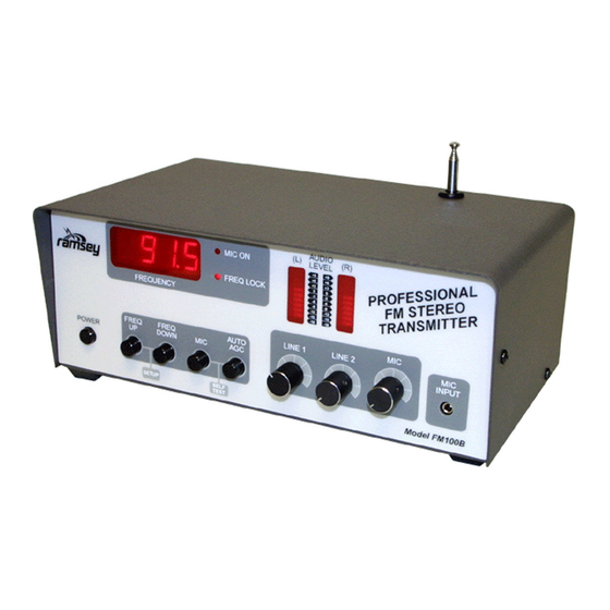
Now here's the ultimate radio transmitter for all of you home
brew DJs out there! This all-in-one stereo transmitter has all
the features you will ever need for transmitting for a school
radio station, around your yard, or even around the block.
With an optional high power module for out of the US
transmitting, this is definitely a professional unit!
•
2 Line inputs and one mic input-plus a built in mixer!
•
PLL Crystal controlled for rock solid frequency
•
Left and right channel peak hold indicators and large LED
frequency display
•
Built in power supply, just plug it in!
•
25mW output standard, optional 1W module for foreign
country operation
•
Auto AGC microphone muting function for cool talk overs
•
Rugged steel enclosure for years of use
FM-100
Advertisement
Table of Contents
Troubleshooting

Related Manuals for Ramsey Electronics FM-100


Summary of Contents for Ramsey Electronics FM-100
- Page 1 Ramsey Electronics Model No. FM-100 Now here’s the ultimate radio transmitter for all of you home brew DJs out there! This all-in-one stereo transmitter has all the features you will ever need for transmitting for a school radio station, around your yard, or even around the block.
- Page 2 COPYRIGHT 1996 by Ramsey Electronics, Inc. 793 Canning Parkway, Victor, New York 14564. All rights reserved. No portion of this publication may be copied or duplicated without the written permission of Ramsey Electronics, Inc. Printed in the United States of America. FM-100 Page 2...
-
Page 3: Table Of Contents
Introduction ........4 How does it work ......5 Parts List ...........13 Assembly Index ........16 Section Layout ........17 Display Layout ........18 Main Board Layout ......21,22 Schematic Centerfold .......34,35 Troubleshooting ........51 Using the FM-100 ......57 FCC Rules and Information ....58 FM-100 Page 3... -
Page 4: Introduction
First we will begin with a little history of stereo transmitters at Ramsey Electronics to give you some idea how we arrived at the FM-100 as our latest stereo transmitter. We have many people call us each day asking questions about our earlier versions of transmitters such as the FM-25 and the FM-10a. -
Page 5: How Does It Work
FCC regulations section. Otherwise there is some insight into why and how this FM-100 works. We will use the schematic located at the center of the manual to analyze the circuit. - Page 6 D10. In this way the output frequency of U6 is "locked" to that desired by the microcontroller. Meanwhile U4 is polling pin 11, the LD (Lock Detect) output of U2 to determine if the PLL can achieve a “lock” or not. FM-100 Page 6...
- Page 7 U7, a voice detector chip is used in this circuit. It has a couple features that we use in the FM-100 that really help us out. One feature is the AGC or Automatic Gain Control. This prevents us from overloading the audio circuitry by getting excited and yelling in the microphone.
- Page 8 The second neat feature is the voice detection capability. Voice detection is used with the auto AGC feature of the FM-100. Essentially pin 8 of U7 goes high when there is a varying signal level seen on the microphone, as compared to the constant level of background noise.
- Page 9 100, but you may be interested in more detail of how it works. If so, there are many good books and magazines which deal with circuitry of this sort in smaller manageable circuits which can help you delve further in what is going on. FM-100 Page 9...
- Page 10 11. Continue polling LD and updating status indicators. We hope all of this information helps you understand better what is going on in the FM-100, and will lead to some insight when you are having assembly troubles or something isn’t working properly. Remember most projects like this are made up of many smaller ones, all you have to do is break them down to understand them better.
- Page 11 The part is then soldered securely to the board (2-4), and the remaining lead length is then clipped off (5). Notice how the solder joint looks on close up, clean and smooth with no holes or sharp points (6). FM-100 Page 11...
-
Page 12: Parts List
If a problem does occur, the manual will lead you through step by step in the troubleshooting guide until you find the problem and are able to correct it. FM-100 Page 12... - Page 13 1 MC145170 Serially programmed PLL (U2) 1 BA1404 Stereo generator IC (U6) 2 LF347 Quad low noise opamps (U11,8) 1 68HC705J2 Custom programmed microcontroller (U4) Marked FM-100 1 X2402 serial EEPROM (U1) 2 LM3915 Log bar-dot bargraph display drivers (U12,U5)
- Page 14 1 100K ohm trimmer (orange top marked 104) (R15) Inductors 1 adjustable shielded metal can coil or similar (L1) 4 40nH coils (small 4 turn air coils) (L2,3,5,6) 1 Small red torroid core (L4) 8” #26 enamel wire for winding (L4) FM-100 Page 14...
- Page 15 1 Roll of fine 60/40 solder (less than .045” diameter) 1 Sensitive voltmeter or DMM 1 An FM radio for testing 1 Audio sources such as a tape deck, CD player, or microphone 1 Egg carton or grapefruit holder to sort out parts in. FM-100 Page 15...
- Page 16 [K] Power Supply ........41 [L] 1 Watt Module ........44 [M] Rear panel wiring ......45 [N] Front Panel Assembly ...... 47 [O] PCB Mounting ........47 [P] Final Testing and Calibration ... 48 [Q] Final Case-up ........50 FM-100 Page 16...
-
Page 17: Section Layout
SECTION LAYOUT ON MAIN BOARD FM-100 Page 17... - Page 18 DISPLAY BOARD LAYOUT Parts Values Parts Layout Note: Gray components are on the reverse side of the board. FM-100 Page 18...
- Page 19 1 on these. In this case we want to orient the lettering on the one side towards U3, so that when looking at the display, the lettering is facing downward. Solder all 18 pins. 10A. Install DS1, the other two digit display. Again orient the lettering FM-100 Page 19...
- Page 20 Cool! We have just completed the display board and we are almost ready to move on. First we want to check our display board to make sure there are no solder bridges or cold solder joints. Next check orientation of your parts for correct installation. FM-100 Page 20...
- Page 21 MAIN BOARD PART VALUES FM-100 Page 21...
- Page 22 MAIN BOARD PART LAYOUT FM-100 Page 22...
- Page 23 The end of the metal latch furthest from the but- ton end is gently lifted up and out to the side, while the other end remains in place to keep the spring there. FM-100 Page 23...
- Page 24 16C. Install C42, a 10uF electrolytic capacitor. Polarity! 17C. Install C59, a 47uF electrolytic capacitor. Again check polarity! 18C. Install C39, a 10uF electrolytic capacitor. Orientation! 19C. Install C12, a 2.2uF electrolytic capacitor. Polarity again! 20C. Install C47, a 47uF electrolytic capacitor. FM-100 Page 24...
- Page 25 19D. Install C69, a 10uF electrolytic capacitor. 20D. Install C43, a 10uF electrolytic capacitor. 21D. Install Q4, a BS170 FET. When looking at this part, you will notice that the center lead is bent slightly opposite of how we are going to install FM-100 Page 25...
- Page 26 You would be surprised how many problems you can find when you do this. Sort of like getting up and leaving one marriage for a fresh, new per- spective? Onward! FM-100 Page 26...
- Page 27 15E. Install C46, a 100pF ceramic capacitor (marked 100 or 101). 16E. Install C61, a .0047uF ceramic capacitor (marked .0047 or 472). 17E. Install C62, a .001uF ceramic capacitor (marked 102 or .001). FM-100 Page 27...
- Page 28 Again check for solder bridges and cold solder joints. Especially check around the pins of the ICs for solder bridges since it is a common occurrence. FM-100 Page 28...
- Page 29 15F. Install D4, another 1N4148 type diode (orange glass body with black stripe on one end). Again check orientation before soldering. This is the rectifier for the other channel. FM-100 Page 29...
- Page 30 (preferably caffeinated) and give yourself an eyeball break. Our next section is the toughest of the whole kit, so make sure you have all of your skills primed and ready for the true test! FM-100 Page 30...
- Page 31 1G. Install JMP5 using a scrap piece of lead wire. Leave the jumper “loop” about 1/4” above the board to allow you to cut it out later. If you wish to operate the FM-100 in mono, this is the jumper you would cut. 2G. Install Y2, the 38KHz crystal found taped to a piece of paper.
- Page 32 25G. Install C30, a 75pF ceramic capacitor (marked 75 or 75K). 26G. Install C29, a 47pF ceramic capacitor (marked 47 or 47K). 27G. Install C9, a .1uF ceramic capacitor (marked .1 or 104). 28G Install C14, a .001uF ceramic capacitor (marked .001, or 102). FM-100 Page 32...
- Page 33 51G. Install C25, a .001uF ceramic capacitor (marked .001 or 102). 52G. Install C6, a 10uF electrolytic capacitor. Polarity! 53G. Install C1, a 27pF ceramic capacitor (marked 27 or 27K). 54G. Install C2, another 27pF ceramic capacitor (marked 27 or 27K). FM-100 Page 33...
- Page 34 But still be careful of your assembly, you wouldn’t want to get this far and then make a mistake causing the project not to work. With soldering iron in hand, on to the next section! FM-100 Page 34...
- Page 35 15H. Install C17, a .01uF ceramic capacitor (marked .01, 10n or 103). 16H. Install J1, a 5 pin jumper header. Make sure the shorter ends are installed into the board. This will be the connection to the digit display. FM-100 Page 35...
- Page 36 Install it in the same orientation as shown in the parts layout diagram. 18H. Install U4, the IC with the sticker FM-100 into the socket.If your chip has a dot or notch, orient as shown in the parts layout diagram. If your chip has a large “1”...
- Page 37 11J. Install J5, one of the stereo RCA jacks. Make sure and mount these so the back is square in relation to the PC board and that the jack is mounted flush to the PC board. FM-100 Page 37...
- Page 38 (whoops!). We just want to make sure you don’t need to send back this for something easily repaired yourself. To assist you in checking your project out, have an associate check your work for you, you may be surprised what they point out for you! FM-100 Page 38...
- Page 39 (there is always going to be some present in varying degrees). This RF modulation is detected in some circuits like opamps and the BA1404 causing 60Hz hum and other noises. The capacitors reduce the problem dramatically when placed across each diode. FM-100 Page 39...
- Page 40 Make sure you install this correctly! If installed wrong, you will destroy your entire kit! You may need to bend the leads around a little before installing in the board. Make sure all six pins are through before soldering. FM-100 Page 40...
- Page 41 The other end will attach to the rear panel mounted antenna jack. Again check all of your work up to this point, especially the orientation of all of the parts in the power supply section. Now we will install the parts for the 1 watt module. FM-100 Page 41...
- Page 42 3M. Thread the line cord through the grommet in the back panel. Make sure the plug end is on the silk screen side of the panel, and the Molex end of the line cord is on the non-silk screen side (inside the case). FM-100 Page 42...
- Page 43 7M. Install the 3” piece of line cord wire with Molex pin attached into the other side of the Molex jack. 8M. Install the fuse holder in the back of the case so that the cap is on the FM-100 Page 43...
- Page 44 PC board, so 110VAC will be present on those also. When we have finished checking out the project, you may coat these connections with insulating glue such as epoxy or silicone glues such as tub sealant. FM-100 Page 44...
- Page 45 You can then set the cover in place without having to screw it down until your initial tests are made. Now we are getting somewhere! Is it ever tempting to plug it in. But wait, flip the page first! FM-100 Page 45...
- Page 46 1P. Adjust R15, R23 and R35 to their center positions. 2P. Make sure the power switch is off. Plug in your FM-100 to 110 volts. 3P. Turn on the FM-100. All of the digits of the display should light, the speaker will beep, and then go to some frequency.
-
Page 47: Troubleshooting
24P. Adjust R15 until the audio quality is good and in stereo. You will need to use your audiophile judgment for this.Generally, leaving R15 in the center of rotation is good. 25P. Any troubles? Consult the troubleshooting section. It will help you know where to look for mistakes. FM-100 Page 47... - Page 48 5Q. Install all five switch buttons on the end of each switch. 6Q. Use the set screw knobs on both of the line level controls, and on the microphone control. You are finished! Now enjoy your project. Remember your FCC rules and regulations before broadcasting. FM-100 Page 48...
- Page 49 SOLUTION: Again check your power supply. If there is a heavy load due to a faulty circuit somewhere, the power regulators won’t regulate, letting raw DC into the audio circuits. PROBLEM: Still lots of AC hum in the audio. FM-100 Page 49...
- Page 50 FM portable radio closest at hand. It is your responsibility to carefully research what FM stations can be listened to with a good system within the transmitting range of your FM-100. This is especially important in the low end of the FM broadcast band (88-92 MHz), where there are numer- ous medium power National Public Radio stations.
- Page 51 After finding a suitable "open" frequency in the 88-108 MHz FM band, adjust the frequency by first getting the FM-100 into setup mode by pressing both FREQ keys at the same time. Then use FREQ UP and FREQ DOWN keys until you hear the carrier frequency on a nearby FM radio.
- Page 52 FM-100. Consult the literature that came with your stereo equipment. Even if you intend use of the FM-100 for your own home and family, it is still your responsibility, in accordance with Part 15 of the FCC Rules, to ensure that this operation does not cause interference to your neighbors.
- Page 53 When you call ask for the TM-100 antenna, and its cost is $39.95. A simple, yet very effective, antenna for the FM-100 consists of a "dipole", set up either horizontally or vertically, and connected to the transmitter output jack through a few feet of coaxial cable (either RG-58, RG-59 or miniature RG-174, available at Radio Shack and other sources).
- Page 54 FM-100 antenna may tend to be uneven because of walls and other VHF path obstacles, you might set up the FM-100's output in a "carrier-current" configuration. If you know how, then do so - safely. If not, you...
- Page 55 USING YOUR FM-100 • Setting the frequency: [1] Press both FREQ UP and FREQ DOWN at the same time. You should hear a confirming low then high tone. The 10’s digit decimal point should blink. [2] Press and hold a FREQ button; the frequency should scroll through the values.
-
Page 56: Fcc Rules And Information
In the United States, this is how the FCC regards your transmitter kit: Licensed FM broadcast stations and their listeners have ALL the rights! Your use of a device such as the FM-100 kit MAY have some limited privileges in locally-unused band space. - Page 57 May, 1990. This is only a brief look at the rules and should not be construed to be the absolute complete legal interpretation! It is up to you to operate within the proper FCC rules and Ramsey Electronics, Inc. cannot be held responsible for any violation thereof.
- Page 58 FM stations, this is a "generous" limitation designed to accommodate cruder FM devices. Properly built and adjusted, the FM-100 kit operates well within this limit. In fact, its signal should sound no "wider" than any other FM station when listening on an ordinary FM radio.
- Page 59 1-meter antenna may indicate a maximum signal field strength of 250µV (In contrast, non-licensed operation from 26.96 to 27.28 MHz is limited to a field strength of 10,000 µV per meter at 3 meters). FM-100 Page 59...
- Page 60 In fact, the most significant distance in the above chart is the 1.9 µV signal strength permissible at 1260 feet (about 1/4 mile), covering a circular area of FM-100 Page 60...
- Page 61 1 or even .5 microvolt "delivered" to the receiver input by antenna. If the antenna is not good, the receiver cannot respond to the presence of fractions of a microvolt of RF energy. FM-100 Page 61...
- Page 62 Lawful use suggestions for the FM-100 1. Build and adjust this kit strictly according to the published instructions. 2. Use the whip antenna supplied.
- Page 63 FCC Part 15 Rules. Operation is subject to the following two conditions: [1] This device may not cause harmful interference, and [2] this device must accept any interference received, including interference that may cause undesired operation. FM-100 Page 63...
- Page 64 Learn the rules...observe them...and have fun in radio! If you enjoyed this Ramsey kit, there's plenty more to choose from in our catalog - write or call today! FM-100 Page 64...
- Page 65 But on rare occasions a sour component can slip through. All our kit parts carry the Ramsey Electronics Warranty that they are free from defects for a full ninety (90) days from the date of purchase. Defective parts will be replaced promptly at our expense. If you suspect any part to be defective, please mail it to our factory for testing and replacement.
-
Page 66: Ramsey Publication No. Mfm
Section Layout ........ 17 Display Layout ........ 18 Main Board Layout ......21,22 Schematic Centerfold ..... 34,35 Troubleshooting ....... 51 Using the FM-100 ......57 FCC Rules and Information ..... 58 REQUIRED TOOLS • Soldering Iron Ramsey #RTS06, (Radio Shack #RS64-2072) •...
Need help?
Do you have a question about the FM-100 and is the answer not in the manual?
Questions and answers