Table of Contents
Advertisement
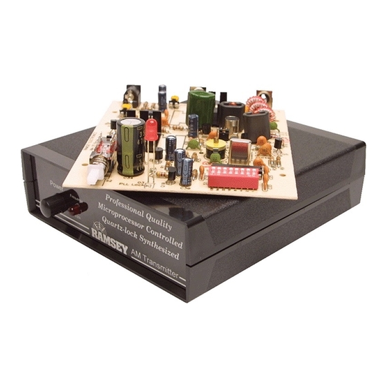
SYNTHESIZED AM
BROADCAST
TRANSMITTER KIT
Ramsey Electronics Model No.
Ever want to be your own disc jockey or talk show host ? Build
and run your own AM broadcast station with this exciting kit !
The AM25 transmitter offers a professional quality signal that is
free from frequency drift and programmable to anywhere in the
AM broadcast band !
•
Great for transmitting your tape deck, CD player, or voice
throughout the house, yard, or car !
•
Powerful enough for high school, college, or neighborhood radio
station - in use the world over !
•
Easily programmed via DIP switch to any clear channel on the AM
broadcast band - from 540 to 1710 KHz.
•
Operates on the same principle as the "big-boys", learn how
commercial transmitters work as well !
•
Superior performance - transmits up to 1/4 mile !
•
Adjustable transmit power level, low pass filtered output.
•
Unit runs on 9 - 15 volts DC.
•
Handy information on FCC rules and antenna hints.
•
Complete and informative instructions guide you to a kit that works
the first time, every time - enhances resale value, too !
•
AM25
1
AM25
Advertisement
Table of Contents

Related Manuals for Ramsey Electronics AM25


Summary of Contents for Ramsey Electronics AM25
- Page 1 Ever want to be your own disc jockey or talk show host ? Build and run your own AM broadcast station with this exciting kit ! The AM25 transmitter offers a professional quality signal that is free from frequency drift and programmable to anywhere in the AM broadcast band ! •...
- Page 2 1994 by Ramsey Electronics, Inc. 590 Fishers Station Drive, Victor, New York 14564. All rights reserved. No portion of this publication may be copied or duplicated without the written permission of Ramsey Electronics, Inc. Printed in the United States of America. •...
-
Page 3: Table Of Contents
Manual Price Only $5.00 KIT ASSEMBLY AND INSTRUCTION MANUAL FOR SYNTHESIZED AM TRANSMITTER AM25 TABLE OF CONTENTS Introduction to the AM25 ....4 AM25 Circuit Description ....4 Schematic Diagram ......7 Parts Layout Diagram ......8 Parts List ..........9 Assembly Instructions ......10 Frequency chart ........18 Alignment Procedures ......19... -
Page 4: Am25 Circuit Description
Recent requests for a synthesized AM type transmitter have been answered with this kit. The Ramsey AM25 transmitter is a true broadcast transmitter, which any person may build and use in accordance with the rules of one’s national telecommunications authority. For U.S. residents, that authority is the Federal Communications Commission (FCC). - Page 5 ‘ol car stereo! It should also be stated that, due to the linear operation of the amplifiers in this circuit (transistors Q8 and Q9 biased partly “on”), this circuit will consume a fair • AM25...
- Page 6 VCO’s RF frequency (f = 1/[2π (LC) ½ ]), bringing the AM25’s output frequency back on frequency. If the desired frequency is higher than the reference, pin 7 is driven low. If the frequency is just right then pin 7 becomes a high impedance, basically disconnecting it from the circuit so it will cause no change in the voltage on D2.
-
Page 7: Schematic Diagram
• AM25... -
Page 8: Parts Layout Diagram
PARTS LAYOUT DIAGRAM • AM25... -
Page 9: Parts List
470 µF electrolytic capacitor (C34) 65 pF trimmer capacitor (C16) INDUCTORS Toroid inductors [red ferrite core] (L1,2,3) binocular toroid cores (L4,6) 68 µH inductor [looks like a resistor with blue-gray-black bands ] (L7) metal can slug tuned variable inductor [marked A7030] (L5) • AM25... -
Page 10: Assembly Instructions
4-40 x 1/4 screw 4-40 kepnut ASSEMBLY INSTRUCTIONS There are numerous solder connections on the AM25 printed circuit board. Therefore, PLEASE take us seriously when we say that good soldering is essential to the proper operation of your transmitter! •... - Page 11 2. Install RCA phono jacks J1 and J2. These connectors will “snap” into place before soldering. Don’t be afraid to completely solder all three ground connections as these will also limit the “stress” on the input and antenna connections. 3. Install the 2.1 mm power connector in the J3 position. • AM25...
- Page 12 We’ll now begin to construct the RF oscillator section of the AM25. Be sure to mount the components as close as possible to the PC board to avoid “radiating” any unwanted signals due to long lead lengths. 4. Install L5, the slug tuned inductor. Solder all 7 tabs.
- Page 13 Q2 makes a neat 6 - 7 volt zener! 37. Install C30, 10 µF electrolytic capacitor, watch polarity. 38. Install JMP1 using a scrap piece of component lead wire. 39. Install R24, 1Meg ohm [brown-black-green]. 40. Install R25, 10K ohm resistor [brown-black-orange]. • AM25...
- Page 14 61. Install C2, 2200 pF disc capacitor [marked .0022 or 222 or 2200K]. 62. Install C6, another 2200 pF disc capacitor. This completes all of the transmitter RF portion except for the low-pass filter section and the ‘binocular’ shaped inductors L4 and L6. Let’s get busy winding these inductors. • AM25...
- Page 15 71. Tin the wire ends and line them up as you did before with the twisted pair in the middle. 72. Install L6, the 4 turn end installs into the hole near L5, the twisted pair into the center hole and the 2 turn end faces R16. • AM25...
- Page 16 95 Install R13, 1K ohm [brown-black-red]. 96. Install R22, 10K ohm [brown-black-orange]. 97. Install R29, 1K ohm [brown-black-red]. The following transistors are capable of higher power than the little guys you’ve been installing. Because of their higher power abilities, they will • AM25...
- Page 17 AM25 Final Assembly Instructions You’ll need to determine what frequency you wish to set your transmitter to. It really is not sufficient to just “check” the AM band for an empty frequency, using the AM radio closest at hand.
-
Page 18: Frequency Chart
106. Referencing the frequency table, Plug the jumper block over the proper pin numbers on Header block H1. You have just completed your AM25 wireless broadcast transmitter. Take a well deserved break now. Give your eyes a rest. When you return, be sure to check over your work on the entire circuit board. -
Page 19: Alignment Procedures
Keep all tests very brief until you have carefully chosen an open operating frequency in the AM broadcast band. Remember, to optimize the performance of your AM25 the PC board ground should be connected to earth ground. The simplest way to accomplish this is to run a jumper from the board ground to a cold water pipe or to a ground rod implanted several feet into the earth. -
Page 20: Troubleshooting
CD player. Most stereo systems have a line level output jack. 11. Adjusted as indicated, your AM25 will produce 100 mW of RF power which conforms with FCC rules. If you live outside of the USA you may jumper across resistors R33 and R34 to allow the AM25 to generate 1 watt of RF power. -
Page 21: Antenna Experimenting
Licensed Broadcast stations and their listeners have all the rights! Your non- licensed use of any device such as the AM25 has absolutely no rights at all over the rights of a licensed broadcast operator. If your operation of the AM25 interferes with anyone’s use or enjoyment of an FCC licensed... - Page 22 Connect an 8 foot whip antenna to one J1, RF Output end of the coil and the other end to the center pin of the antenna output jack. Experiment with different designs to determine which antenna type works best for you. • AM25...
-
Page 23: Ramsey Kit Warranty
'1K ohm' resistors are actually the 'missing' 10 K parts ("Hum-m-m, I guess the 'red' band really does look orange!") Ramsey Electronics project kits are packed with pride in the USA. If you believe we packed an incorrect part or omitted a part clearly indicated in your assembly manual as supplied with the basic kit by Ramsey, please write or call us with information on the part you need and proof of kit purchase. -
Page 24: Ramsey Electronics, Inc
Desoldering Braid (RTS08) • DC Voltmeter (D980) Manual Price Only: $5.00 Ramsey Publication No. MAM25 Assembly and Instruction manual for: RAMSEY MODEL NO. AM25 SYNTHESIZED AM TRANSMITTER KIT RAMSEY ELECTRONICS, INC. 590 Fishers Station Road Victor, New York 14564 Phone (585) 924-4560 •...
Need help?
Do you have a question about the AM25 and is the answer not in the manual?
Questions and answers