
Related Manuals for Ramsey Electronics PX50


Summary of Contents for Ramsey Electronics PX50
- Page 1 USER GUIDE FEBRUARY, 2005 V2.1.4 PX50 FM STEREO TRANSMITTER Copyright Ramsey Electronics, Inc. 2005, All rights reserved...
- Page 2 IC:4318A-PX50 This unit complies with BETS-6 Technical Standards for Licensed FM Broadcast Station Transmitters (Canada) WARNING: Changes or modifications not expressly approved by Ramsey Electronics, Inc. could void the user’s authority to operate the equipment MODEL: PX50 DESCRIPTION:...
-
Page 3: Table Of Contents
4.06 Audio Inputs ..................... 11 4.07 MPX Input ....................11 4.08 Pilot Output....................11 4.09 Antenna...................... 11 5.00 Using the PX50 Front Panel Interface............12 5.01 Navigation Control and Display ............12 5.02 General Display..................12 5.03 Audio Display.................... 12 5.04 VSWR Display.................... - Page 4 5.12 Set Station ID.................... 15 5.13 Set Auto Power ..................15 5.14 Set Power Fault..................16 5.15 Set Power Fault Timer................16 5.16 Set Test Timer................... 16 5.17 Set Control Lock ..................17 5.18 Quiet Mode ....................17 5.18 Super User Mode ..................17 6.00 Appendix ......................
-
Page 5: Introduction
1.00 INTRODUCTION The PX50 has been carefully inspected and packed by Ramsey Electronics, Inc. for shipping. Upon receipt please check the carton and look for any visible damage and notify the carrier immediately. 1.01 Checking the Contents The PX50 FM Stereo Transmitter package includes the following:... -
Page 6: Features
2.00 PX50 FEATURES The PX50 is state of the art 50 watt FM stereo transmitter designed for commercial FM, LPFM and international use over the frequency range of 87.5 MHz to 108.1 MHz. The RF output level is continuously variable from 1 watt to 50 watts. The transmitter is housed in a compact 2 rack-unit enclosure for easy installation. -
Page 7: Use It Anywhere In The World
85-264VAC between 47-63Hz, or 120-370VDC and you’re all set. It does- n’t get much easier than that! You can also run the PX50 primary power from 12- 14VDC. You can even provide 12-14VDC from a battery (or vehicle) and have auto-... -
Page 8: Px50 Overview
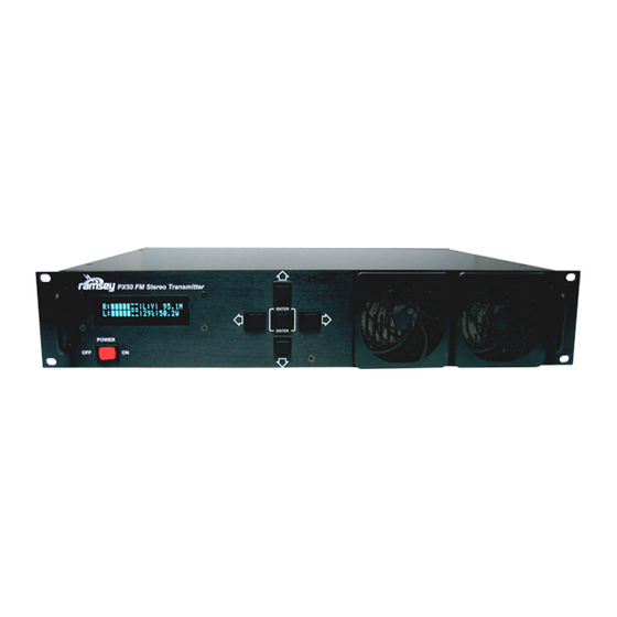
3.00 PX50 OVERVIEW 3.01 Front Panel 2-line vacuum fluorescent display Power on/off switch 5-way navigation switch matrix Filtered forced air input, do not block air flow 3.02 Rear Panel Forced air exhaust port, do not block air flow RF output, 50 ohm... -
Page 9: Internal Layout
3.03 Internal Layout Air Exhaust Low Pass Filter Board Audio Input Board 50W Power Amp Cooling Fan Main Board Power Supply Controller Board Air Intake Your Notes:... -
Page 10: Installation And Initial Setup
Appendix A in this manual. 4.03 Rack Mount Installation The PX50 is one standard rack unit (1.75”) and is designed to be installed in a standard 19” equipment rack or rack mount enclosure. Care should be taken to allow adequate ventilation to assure proper cooling of the transmitter. -
Page 11: Secondary Dc Power
4.05 Secondary DC Power The PX50 is also equipped for 12V DC power operation. This can be used for primary power in the field, or backup power to your primary AC source. If your are using 12 VDC to power the unit, you do not need to make any adjustments to the settings on the power supply. -
Page 12: Using The Px50 Front Panel Interface
EEPROM of the microcontroller when you scroll to the next screen. If you do not scroll to the next screen, the PX50 assumes you are simply testing this change and will not save it during a power cycle. Again, the Up/Down arrow keys are used to change to the next/previous menu screens. -
Page 13: Temperature Display
Temperature fault will be triggered, and the amplifier will automatically power down to 0 Watts to cool for a while. Power will resume once the temperature falls be- low 60 degrees Celsius. The power level that the PX50 will return to is set in menu 13 (Power Fault). -
Page 14: Set Audio Modulation Limiting (Aml)
For your convenience there is also an automatic level adjustment. If you press the Enter key for 5 beeps on this display, the PX50 will sample the audio for a period of time and look at all of the peaks. Then it will adjust the audio levels for you to prevent over- modulation. -
Page 15: Set Rf Output Power
The amplifier will track and lock to that power setting as shown on the second line of the display. The PX50 will periodically compare this power setting with the measured output power, and make adjustments to maintain power over a variety of conditions such as reduction in supply voltage, temperature changes, or antenna changes. -
Page 16: Set Power Fault
VSWR fault. The other possible fault condition is a Temperature fault, in which the PX50 will return to the specified power level set in menu 13 only af- ter the temperature drops below 60 degrees C, regardless of how long it takes. Use the right and left arrow keys to select a time from the following options: 0min, 1min, 5min, 10min, 30min, 60 min, 2hrs, 6hrs, 12hrs, or 24hrs. -
Page 17: Set Control Lock
5.19 Super User Mode The PX50 has a “Super User” mode with additional screens for trained technicians only. Adjustments in this mode could seriously effect the proper operation and calibration of the PX50 transmitter making it non compliant with agency requirements. -
Page 18: Appendix
6.01 APPENDIX A: FREQUENCY ASSIGNMENTS FM Broadcast Frequency Plan, US Within the US, the FCC has allocated 100 channels within the FM Broadcast Band. Each channel is allocated 200 kHz of bandwidth. Designator Frequency MHz Designator Frequency MHz Designator Frequency MHz 87.9 94.7 101.5... -
Page 19: Appendix B: Troubleshooting
Ramsey Technical Support. PROBLEM: Everything seems to work, but I have no RF output power. SOLUTION: The PX50 has an intelligent integrity checker built in to protect the transmit- ter. Antenna VSWR, frequency lock, and temperature is continually monitored. If they fall beyond a set range, the transmitter is disabled for protection. - Page 20 Verify with a receiver in the field. PROBLEM: PX50 didn’t save my changes. SOLUTION: When you are in a screen editing a value you are in a scratch pad mode.
-
Page 21: Appendix C: Operating Temperature Characteristics
The key to a continuous duty, long running transmitter is keeping it cool. Make sure not to block the airflow to the transmitter, and to frequently check the air filters. The PX50 has an automatic over temperature shutdown at 70° C Running the PX50 hot will shorten its lifespan considerably, especially at temperatures over 60°... -
Page 22: Specifications
PX50 SPECIFICATIONS Frequency Range: 87.5 to 108.1 MHz Primary Power Input: 85-264 VAC, 47-63 Hz; 120-370 VDC Backup Power Input: 12-14 VDC Broadcast Modes: Stereo/Mono + SCA and Digital RDS Inputs. Bandwidth: ±75 kHz when properly adjusted, auto adjust feature prevents overmodulation. -
Page 23: Warranty
Tech Support will help you diagnose your problem and, if necessary, issue an RMA for the return of your PX50. Equipment cannot be returned without a proper RMA number. With your return, please include specific descriptions of the problem encountered as well as detailed contact information including daytime telephone number, E-Mail address, and complete return shipping address information. - Page 24 PX50 February 2005 V2.1.4 Copyright Ramsey Electronics, Inc. 2005, All rights reserved...
Need help?
Do you have a question about the PX50 and is the answer not in the manual?
Questions and answers