Table of Contents
Advertisement
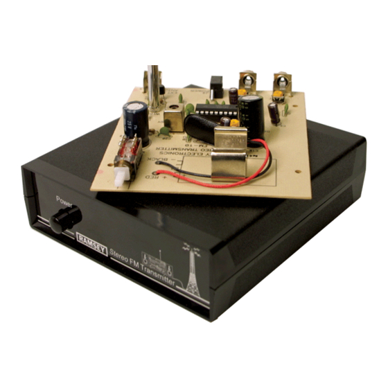
FM STEREO
TRANSMITTER
Ramsey Electronics Model No.
Own and operate your own FM Stereo broadcast station.
Definitely not a toy, the FM-10C has an exceptional transmission
range... and the audio quality puts your favorite radio station to
shame. See why this is one of our most popular kits!
Great for transmitting your tape deck or CD player throughout the
house, yard or even your car.
Powerful enough for college or neighborhood radio stations - in
use all over the world.
Fantastic audio quality sounds better than most stations on the
dial. And we'll tell you why!
Easily connects to the line-level outputs on any tape deck, stereo
system or CD player.
Some users hook up one channel to the scanner and the other to
their two way radio. Now you can hear what's going on around
town up to several blocks away from your house with a simple
stereo receiver... and adjust the volume of each individually with
your balance control!
Add a mike-mixer and tape/CD deck for a "PRO" sounding station.
Operates on 5 to 20 volts, using a crystal controlled subcarrier.
Tunable anywhere in the 88-108 MHz FM band.
FM10C 1
FM10C
Advertisement
Table of Contents

Related Manuals for Ramsey Electronics FM10C


Summary of Contents for Ramsey Electronics FM10C
- Page 1 FM STEREO TRANSMITTER Ramsey Electronics Model No. FM10C Own and operate your own FM Stereo broadcast station. Definitely not a toy, the FM-10C has an exceptional transmission range... and the audio quality puts your favorite radio station to shame. See why this is one of our most popular kits! ...
- Page 2 COPYRIGHT 2007-2010 by Ramsey Electronics, LLC, 590 Fishers Station Drive, Victor, New York 14564. All rights reserved. No portion of this publication may be copied or duplicated without the written permission of Ramsey Electronics, LLC. Printed in the United States of America.
-
Page 3: Table Of Contents
Assembly Instructions ..........11 Choosing an Operating Frequency ......16 Schematic Diagram ..........18 Adjusting your FM10C ..........20 Using FM10C Within the Home ........ 21 Power Supply Considerations ........21 LED Power On Indicator ........... 21 Experimental Broadcasting Projects ......22 Antenna Ideas ............ -
Page 4: Introduction To The Fm10C
FM10C is definitely not a toy. We will refer to the FCC regulations frequently in this manual and provide you with some information necessary to enjoy the FM10C's capabilities in accordance with the law. -
Page 5: Fm10C Circuit Description
U1 FM Stereo Transmitter IC FM stereo transmitter IC (U1) is at the heart of the FM10C. It contains a ste- reo modulator that develops a main L+R signal, a sub (L-R) signal, a 19kHz pilot signal, and RF Carrier (88-108 MHz). - Page 6 RF Oscillator This oscillator consists of U1, C19, C20, L4, and C18. The setting of L4 and the value of C18 sets the RF Carrier frequency that is received by a standard FM radio. RF Amp C22 is a coupling capacitor that allows the RF output at U1 pin 7 to be passed to the transistor Q1.
-
Page 7: Parts Layout Diagram
FM10C PARTS LAYOUT DIAGRAM FM10C 7... -
Page 8: Parts List
PARTS LIST CAPACITORS 1 1 pf disc capacitor [marked 1] (C26) 4 10 pf disc capacitor [marked 10 or 10K] (C11,12,19,20) 1 15 pf disc capacitor [marked 15] (C18, see note #1 at end of list) 1 22 pf disc capacitor [marked 22] (C18, see note #1 at end of list) 1 27 pf disc capacitor [marked 27] (C18, see note #1 at end of list) 3 100 pf disc capacitor [marked 100 or 101] (C1,C2,C3) 1 220 pf disc capacitor [marked 220 or 221] (C13) - Page 9 1 2.1 MM power jack (J3) 1 F-type PC-mount jack (J4) HARDWARE AND MISCELLANEOUS 1 Ramsey FM10C Printed circuit board 1 38 KHz crystal [small silver cylindrical "can" with 2 small leads], taped to a piece of paper. 1 PC board mounted DPDT switch 1 18 pin IC socket for BA1404...
- Page 10 RAMSEY “LEARN-AS-YOU-BUILD” ASSEMBLY STRATEGY Be sure to read through all of the steps and check the boxes as you go to be sure you didn't miss any important steps. Although you may be in a hurry to see results, before you switch on the power check all wiring and capacitors for proper orientation.
-
Page 11: Assembly Instructions
4. Solder all connections unless directed otherwise. Use enough heat and solder flow for clean, shiny, completed connections. ASSEMBLING THE FM10C Sort out all of your parts to begin with, making sure you have all of the parts required. You can use old egg cartons to hold various parts to make them easier to find. - Page 12 12. Install C6, another .0047uF ceramic capacitor (marked 472). 13. Install R5 and R6, a 15K ohm resistor (brown-green-orange). These resistors set the pre-emphasis characteristics for the FM10C at 75 uS for use in the USA. Pre-emphasis is a technique used in FM transmitters to increase the high frequency signal to noise ratio.
- Page 13 Set it flush to the PC board before soldering all six pins. 27. Install C9, a 100uF electrolytic capacitor. Remember polarity! 28. Install C4, a 1000uF electrolytic capacitor. Polarity. FM10C 13...
- Page 14 29. Install L3, a 2.2uH inductor (red-red-gold). This part is located be- tween L4 and the power jack J3. 30. Install C16, a .001uF ceramic capacitor (marked 102). This part is near the audio section. 31. Install J3, the 2.1mm DC power jack. You can gently bend the leads to keep this part from falling out of the board when you flip the board over to solder it.
- Page 15 PC board holes. Solder the pads on the board first then square-up the clamp to the board and solder it to the looped wire. 58. Install the battery snap connector (without battery); The red wire is positive and the black wire is negative. FM10C 15...
-
Page 16: Choosing An Operating Frequency
FM10C FREQUENCY RANGE SELECTION Capacitor C18 sets the frequency range of the FM10C. R8 sets the pilot level for the different bands. Values for C18 and R8 are as follows: Desired Frequency of Transmission C18 Value R8 Value Lower end of FM band... - Page 17 Part 15 of FCC regulations, it is your responsibility to determine carefully that your operation will not cause interference to broadcast reception. Please study Appendix A of this manual before using your FM10C. CASE ASSEMBLY 1. Place the case bottom (has four mounting holes for circuit board) in front of you so that the tongue side is on the right and the groove side is on your left.
-
Page 18: Schematic Diagram
FM10C REV2.1 SCHEMATIC DIAGRAM FM10A 18... - Page 19 FM10C 19...
-
Page 20: Adjusting Your Fm10C
Back R4 down slightly until distortion disappears. Re- peat the process for the right channel and R3. Hooking up an audio source to your FM10C is really quite simple. However, there are some general rules: ... -
Page 21: Using Fm10C Within The Home
USING THE FM10C WITHIN THE HOME A most practical use for the FM10C would be to connect it to the main stereo system within a large home so that whatever is playing on the main system can also be tuned-in on portable FM radios in other rooms, the garage or out in the yard. -
Page 22: Experimental Broadcasting Projects
4. The more home-built your complete setup, the more it is in conformity with the spirit of FCC Part 15 regulations. If you are designing the FM10C and its mixing inputs to serve as an educa- tional and entertaining toy for your children, we suggest that the FM10C PC board be incorporated with the mixing circuits into a durable, non-hazardous enclosure. -
Page 23: Antenna Ideas
(STC1) for a “radio station” quality home broadcasting set-up. ANTENNA IDEAS The simplest, yet very effective, antenna for the FM10C consists of a "dipole", set up either horizontally or vertically, and connected to the transmitter output jack through a few feet of coaxial cable (either RG-58, RG-59 or miniature RG -174, available at Radio Shack and other sources). -
Page 24: Troubleshooting Guide
If you know how to do correctly, then do so - safely. If not, you can show your FM10C and this book to a licensed radio engineer and negotiate with that person for a safe installation which will feed your sig- nal through interior wiring of your home or building. -
Page 25: Appendix A: Fcc Rules And Information
In the United States, this is how the FCC regards your transmitter kit: Licensed FM broadcast stations and their listeners have ALL the rights! Your use of a device such as the FM10C kit MAY have some limited privileges in locally-unused band space. - Page 26 15.221. Use our AM-1 AM radio broadcast kit for this use. 6. FCC Rule No. 15.239 specifically addresses operation in the 88-108 MHz FM broadcast band for which your FM10C transmitter kit is designed. However, this Rule does not, by itself, tell you everything you need to know about using a device of this kind.
- Page 27 (FCC rule 15.239). If you have any concern about this emission limit, have your device checked by a technician with accurate measuring equipment. Remember that the "field strength" of a signal is determined as much by the antenna as by the RF output of the transmitter itself. FM10C 27...
-
Page 28: Appendix B: Understanding Field-Strength
APPENDIX B: UNDERSTANDING LEGAL "FIELD STRENGTH" A "microvolt" is one-millionth of one volt and designated "µV" in the following explanations. The new FCC Part 15 Rules specify a maximum "Field Strength" of your transmitted signal. Since it is unlikely that you have the equipment to carry out accurate field strength measurements in microvolts, it is useful to under- stand at least the theory of field strength so that you can understand both what you can expect from such transmitters, and what limits the FCC intends. - Page 29 In fact, the most significant distance in the above chart is the 1.9 µV signal strength permissible at 1260 feet (about 1/4 mile), covering a cir- FM10C 29...
-
Page 30: Summary
The present edition of Part 15 of the FCC rules does not provide detailed guidance on ALL aspects of using a low-power transmitter such as the FM10C. The main point is that you may not cause any interference whatso- ever to licensed broadcast services and that you must be willing to put up with any interference that you may experience. - Page 31 Inc. to conform to applicable provisions of Part 15 of FCC Rules. The indi- vidual kit-builder and all users of this device assume responsibility for lawful uses conforming to FCC Part 15 Rules. Operation is subject to the following two conditions: FM10C 31...
- Page 32 [1] This device may not cause harmful interference, and [2] this device must accept any interference received, including inter- ference that may cause undesired operation. Final comment A well-informed person will see today's FCC Rules to be evolving and pro- gressively less-restrictive.
-
Page 33: Specifications
FM10C SPECIFICATIONS Frequency of Operation: 88 to 108 MHz Bandwidth: +/- 75 kHz when properly adjusted RF Output Jack: Power: Approximately 10mW Antenna on board: 33-1/2 inch (0.85m) telescopic whip Audio Input Jacks: RCA (x2) Impedance < 10k ohms Signal... - Page 34 NOTES ______________________________________________________________ ______________________________________________________________ ______________________________________________________________ ______________________________________________________________ ______________________________________________________________ ______________________________________________________________ ______________________________________________________________ ______________________________________________________________ ______________________________________________________________ ______________________________________________________________ ______________________________________________________________ ______________________________________________________________ ______________________________________________________________ ______________________________________________________________ ______________________________________________________________ ______________________________________________________________ ______________________________________________________________ ______________________________________________________________ ______________________________________________________________ ______________________________________________________________ ______________________________________________________________ ______________________________________________________________ ______________________________________________________________ ______________________________________________________________ ______________________________________________________________ ______________________________________________________________ ______________________________________________________________ ______________________________________________________________ ______________________________________________________________ FM10A 34...
-
Page 35: Fm10C Kit Warranty
“1K ohm” resistors are actually the “missing” 10 K parts ("Hum-m-m, I guess the orange band really does look red!") Ramsey Electronics project kits are packed with pride in the USA by our own staff personnel. - Page 36 Advanced ..... 2.5 hrs RAMSEY ELECTRONICS, LLC Manual Price Only: $5.00 590 Fishers Station Drive Ramsey Publication No. MFM10C Victor, New York 14564 Assembly and Instruction manual for: Phone (585) 924-4560 RAMSEY MODEL NO. FM10C (585) 924-4555 FM STEREO TRANSMITTER FM10A 36 www.ramseyelectronics.com...
Need help?
Do you have a question about the FM10C and is the answer not in the manual?
Questions and answers