Table of Contents
Advertisement
DIGITAL FM
TRANSMITTER KIT
Ramsey Electronics Model No.
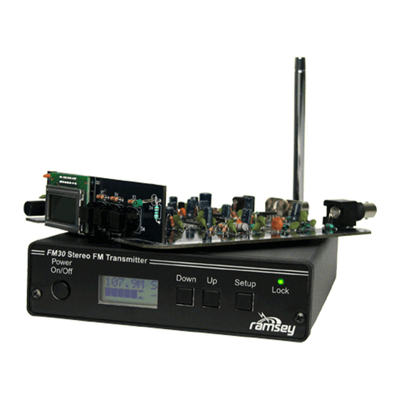
A new and improved version of our popular stereo transmitter
kits, the FM30 is an ideal upgrade for improved performance
and ease of use! With a low-noise design and a metal case, the
FM30 suffers from much less interference for a better S/N ratio.
The FM30 also has full digital front panel control of output
power, volume, balance, stereo/mono, and frequency!
•
Synthesized 87.9MHz to 108.1MHz for no frequency drift! Direct
digital input of frequency, no jumpers or DIP switches!
•
Designed for extruded, rugged metal case, all lines have RF
chokes, and fully regulated for the cleanest sounding low noise
performance yet!
•
BNC style RF output for easy, reliable connections.
•
Fully digitally controlled transmit power for custom coverage
capabilities!
•
Digital volume and balance controls for easy audio level
adjustments.
•
Runs from 13.8-16VDC, includes 15V DC adapter.
•
Quality of signal indicator lets you know when you have a good
signal or over-modulated signal. Lets you know when to turn it up,
or down!
•
Great for schools, health clubs, yard casting, drive-in movie
theaters, haunted rides, amusement parks, churches, etc!
STEREO
FM30• 1
FM30
Advertisement
Table of Contents

Related Manuals for Ramsey Electronics FM30


Summary of Contents for Ramsey Electronics FM30
- Page 1 FM30 is an ideal upgrade for improved performance and ease of use! With a low-noise design and a metal case, the FM30 suffers from much less interference for a better S/N ratio. The FM30 also has full digital front panel control of output power, volume, balance, stereo/mono, and frequency! •...
- Page 2 2004 by Ramsey Electronics, Inc. 590 Fishers Station Drive, Victor, New York 14564. All rights reserved. No portion of this publication may be copied or duplicated without the written permission of Ramsey Electronics, Inc. Printed in the United States of America. FM30• 2...
-
Page 3: Table Of Contents
Circuit Description........ 5 “Learn as you Build”......10 FM30 PC Board Parts Layout.... 11 FM30 Parts List........12 FM30 PC Board Assembly Steps ..14 FM30 Schematic Centerfold ....20 FM30 Setup ........26 Antenna Ideas........29 Appendix A: FCC Rules and Info..31 Appendix B: ........ -
Page 4: Introduction
FM30 is not a toy. We will refer to the FCC regulations frequently in this manual and provide you with some information necessary to enjoy the FM30's capabilities in accordance with the law. -
Page 5: Circuit Description
We will begin by talking about the new and improved power supply section of the FM30. First off take a look at L1, C8, and C7. Does that look like anything familiar? That is a low-pass filter designed to remove any RF from leaving the... - Page 6 In our case, the comparator is designed to detect peaks over +/-75kHz of deviation, which is the standard bandwidth used by radio stations. If you run the volume up too high on the FM30, the comparator reference level is surpassed often, the micro counts this, and an indicator on the display will show a poor quality of signal indication.
- Page 7 So what actually tunes the VCO you may ask? Good question. A PLL uses a phase comparator to compare the crystal frequency with the oscillator frequency combined with some internal dividers which are programmable. If the frequency is too low, U3’s PLL tells pin 7 to turn up the voltage. This signal FM30• 7...
- Page 8 U3 on pin 11 is small, just enough to cover a room, so we need to boost it a little. U8 is a high-gain amplifier which will get up the level for us so the FM30 has a little more “oomph”. However we don’t want too much “oomph” where we don’t need it, so before the final amp we have D8, which is another special...
- Page 9 COMPARATOR, VARACTOR DIODE, PIN DIODE, LOW PASS FILTER, DIGITAL POT, DAC (Digital to Analog Converter), JFET (Q4), MULTIPLEX. Have fun and happy learning! Now on to the kit building... -Ramsey Staff. FM30• 9...
- Page 10 (Diode bands, electrolytic capacitor polarity, transistor shapes, dotted or notched ends of IC's, and so forth.) 4. Solder all connections unless directed otherwise. Use enough heat and solder flow for clean, shiny, completed connections. FM30• 10...
- Page 11 FM30 PARTS LAYOUT DIAGRAM FM30• 11...
-
Page 12: Fm30 Parts List
FM30 PARTS LIST SEMICONDUCTORS 1 LM940CS-12 12VDC low dropout regulator (VR1) 1 1N4000 series power diode (can be any number from 1N4002 to 1N4007 (Black body, grey stripe, marked 1N4002) (D1) 1 1N4148 Small signal switching diodes. (Marked 4148) (D3) - Page 13 2 470pF ceramic surface mount capacitors (C19,20) 1 BH1415F Stereo Modulator IC (U3) 2 10K ohm surface mount resistors (marked 103) (R12,13) 1 TC1320EOA Digital to analog converter (U7) 1 GAL5 DC-8GHz monolithic RF amplifier (U8) Marked o5 FM30• 13...
-
Page 14: Fm30 Pc Board Assembly Steps
FM30 PC BOARD ASSEMBLY STEPS The FM30 is one of our larger, more complicated kits, however, if you follow the steps closely you will find that it will go together smoothly. We will start with the larger main PC board. We’ll have a working kit in no time! 1. - Page 15 Orient the part with the longer lead in the “+” hole and solder the part in. 18. Install R44, 100 ohms (brown-black-brown). 19. Install R30, 56k ohms (green-blue-orange). 20. Install C13, 100uF electrolytic capacitor. Remember to orient the longer positive lead with the ’+’ sign on the board before soldering. FM30• 15...
- Page 16 “+”. 40. Install R2, 10k ohm resistor (brown-black-orange). 41. Install C2, the only 10pF capacitor (marked 10). 42. Install C14, 0.1uF ceramic disc capacitor (marked 104). FM30• 16...
- Page 17 59. Install C32, 10nF or 0.01uF ceramic disc capacitor (marked 103). 60. Install R39, 10k ohm resistor (brown-black-orange). 61. Install C37, 0.1uF ceramic disc capacitor (marked 104). 62. Install C39, 3300pF ceramic disc capacitor (marked 332). 63. Install C40, 150pF ceramic disc capacitor (marked 151). FM30• 17...
- Page 18 82. Install C21, 10uF electrolytic cap. Yes, watch your polarity. 83. Install C46, 1nF or 0.001uF ceramic disc capacitor (marked 102). 84. Install R35, 4.7 ohms (yellow-violet-gold). 85. Install C68, 1nF or 0.001uF ceramic disc capacitor (marked 102). FM30• 18...
- Page 19 D2. Nope, there’s no polarity with a piece of wire! This part was replaced by a jumper to improve the operation of your FM30. 103. Install another wire jumper in the D6 position. Just like D2 before, this part was removed and we need to put a jumper in its place.
-
Page 20: Fm30 Schematic Centerfold
FM30 SCHEMATIC CENTERFOLD FM30• 20... - Page 21 FM30• 21...
- Page 22 PC board before soldering. 121. Moving on to the back of the board, install J3, the 2.1mm center post positive power jack. Again, be sure the part is flat before soldering. 122. Install J10, one of the RCA jacks. FM30• 22...
- Page 23 Be sure these parts are seated nice and flat before soldering. F12. The next part we’ll install is the 2x8 line LCD display. First you’ll need to snap off the two metal tabs on the front of the part to make it ready to FM30• 23...
- Page 24 F18. Now take the front panel board and slide it into its place on the main board. All the pins on J1 should line up with J2 and J4 should line up with F19. Take the connected but not yet soldered boards and slide them into FM30• 24...
-
Page 25: Fm30 Setup
Ok, let’s fire this baby up and see what it will do! FM30 SETUP: It’s time to set up and test your FM30, then get on the air. You’ll need the case, power supply, whip antenna, a small screwdriver or diddle stick, and a line level audio source such as a CD player or computer sound card. - Page 26 Another press of the SETUP button brings us to the volume display. Connect your line level source to the FM30. Your source can be a CD player line out, a computer sound card line output, or any other audio source you desire as long...
- Page 27 NEVER connect the FM30 audio inputs to speaker outputs of a high power stereo system; such a connection will destroy the IC chip. Trust us when we say that a true line level audio source will give you the best results with your FM30.
- Page 28 FM30. Consult the litera- ture that came with your stereo equipment. Even if you intend use of the FM30 for your own home and family, it is still your responsibility, in accordance with Part 15 of the FCC Rules, to ensure that this operation does not cause interference to your neighbors.
-
Page 29: Antenna Ideas
ANTENNA IDEAS A simple, yet very effective, antenna for the FM30 consists of a "dipole", set up either horizontally or vertically, and connected to the transmitter output jack through a few feet of coaxial cable (either RG-58, RG-59 or miniature RG-174, available at Radio Shack and other sources). - Page 30 If your situation involves a single large building or multi-level home where re- ception from the FM30 antenna may tend to be uneven because of walls and other VHF path obstacles, you might set up the FM30's output in a "carrier- current"...
-
Page 31: Appendix A: Fcc Rules And Info
Licensed FM broadcast stations and their listeners have ALL the rights! Your use of a device such as the FM30 kit MAY have some limited privileges in lo- cally-unused band space, but your non-licensed use of the FM30 has abso- lutely NO rights at all over the rights of licensed broadcast operators and the rights of their listeners to interference-free reception. - Page 32 May, 1990. This is only a brief look at the rules and should not be con- strued to be the absolute complete legal interpretation! It is up to you to oper- ate within the proper FCC rules and Ramsey Electronics, Inc. cannot be held responsible for any violation thereof.
- Page 33 FM stations, this is a "generous" limitation de- signed to accommodate cruder FM devices. Properly built and adjusted, the FM30 kit operates well within this limit. In fact, its signal should sound no "wider" than any other FM station when listening on an ordinary FM radio.
- Page 34 1260 feet (about 1/4 mile), covering a circular area of about 114 acres. A quick glance at stereo FM receiver specifications shows typical sensitivity of 1.7 µV before considering high-gain antennas or preampli- fiers. Your non-licensed signal can provide serious competition to a public FM30• 34...
-
Page 35: Summary
The present edition of Part 15 of the FCC rules does not provide detailed guidance on ALL aspects of using a low-power transmitter such as the FM30. The main point is that you may not cause any interference whatsoever to li- censed broadcast services and that you must be willing to put up with any in- terference that you may experience. - Page 36 FCC Part 15 Rules. Operation is subject to the following two conditions: 1. This device may not cause harmful interference, and 2. This device must accept any interference received, including interference that may cause undesired operation. FM30• 36...
- Page 37 As our customers, we value your opinions, comments, and additions that you would like to see in future publications. Please submit comments or ideas to: Ramsey Electronics Inc. Attn. Hobby Kit Department 590 Fishers Station Drive Victor, NY 14564 or email us at: techsupport@ramseymail.com...
- Page 38 This page intentionally left blank for notes and scribbles. FM30• 38...
-
Page 39: Warranty
'1K ohm' resistors are actually the 'missing' 10 K parts ("Hum-m-m, I guess the 'red' band really does look orange!") Ramsey Electronics project kits are packed with pride in the USA. If you believe we packed an incorrect part or omitted a part clearly indicated in your assembly manual as supplied with the basic kit by Ramsey, please write or call us with information on the part you need and proof of kit purchase. - Page 40 TABLE OF CONTENTS Introduction ..........4 Circuit Description ........5 FM30 PC Board Parts Layout ... 11 FM30 Parts List ......... 12 FM30 PC Board Assembly Steps ..14 FM30 Schematic Centerfold ..... 20 Appendix A: FCC Rules and Info ..31 Appendix B:........
Need help?
Do you have a question about the FM30 and is the answer not in the manual?
Questions and answers