FLIR M-series Operator's Manual
Hide thumbs
Also See for M-series:
- Operator's manual (78 pages) ,
- Installation manual (28 pages) ,
- Owner's manual (10 pages)
Table of Contents
Advertisement
Quick Links
Advertisement
Table of Contents

Related Manuals for FLIR M-series


Summary of Contents for FLIR M-series
- Page 1 M-Series 432-0003-00-10 Operator’s Manual Revision 140 January 2011...
- Page 2 © FLIR Systems, Inc., 2010. All rights reserved worldwide. No parts of this manual, in whole or in part, may be copied, photocopied, translated, or transmitted to any electronic medium or machine readable form without the prior written permission of FLIR Systems, Inc.
-
Page 3: Table Of Contents
Operation Tips..............43 Troubleshooting Tips ............. 44 On Screen Messages ............47 Restoring the Factory Network Settings ........ 48 M-Series IP Interface and PC Operations ......... 49 M-Series Web Control ............50 Web Control Functions ............51 UPnP Configuration............. 55 Network Settings .............. - Page 4 Custom Network Applications ..........61 432-0003-00-10 rev 140 M-Series Operator’s Manual...
- Page 5 International Electrotechnical Commission IEEE Institute of Electrical and Electronics Engineers Infrared Joystick Control Unit NMEA National Marine Electronics Association Pan/Tilt Power Over Ethernet SCTE Society of Cable Telecommunications Engineers Software Developer’s Kit Volts, Direct Current Visible 432-0003-00-10 rev 140 M-Series Operator’s Manual...
- Page 6 432-0003-00-10 rev 140 M-Series Operator’s Manual...
- Page 7 Description Thank you for buying your new M-Series thermal imaging system. This man- ual describes the operation of the M-Series camera. If you need help or have additional questions, please call to speak with our support experts (phone numbers listed on the back cover of this manual).
-
Page 8: Warnings And Cautions
Caution: Be careful not to leave fingerprints on the M-Series’s camera optics. Caution: The M-Series requires a power supply of 12 - 24V DC nominal, 5 Amp maximum. Absolute voltage range: 10 - 32V DC. Operating the cam- era outside of the specified input voltage range or the specified operating temperature range can cause permanent damage. -
Page 9: System Description
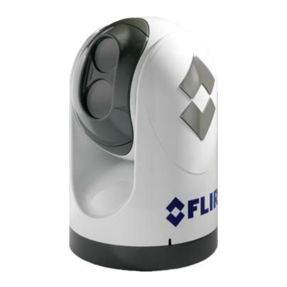
System Description System Description M-Series is a maritime thermal imaging system for use on nearly any kind of vessel. The system is available in two configurations: the single payload model has a single thermal imaging camera, and the dual payload model is equipped with both a thermal imaging camera and a visible-light camera. -
Page 10: Camera Video Options
JCU will be interconnected by means of a network switch. If the net- work switch does not have Power over Ethernet (PoE) capability, a PoE injec- tor may be used to provide power to the JCU. FLIR PoE injectors are available where you purchased your M-Series camera. -
Page 11: Multiple Camera And Jcu Options
Scene JCU Introduction Color The JCU is the primary method of control for the M-Series camera. It can Puck be used to move the camera (pan or tilt), electronically zoom the cameras in and out, switch between infrared and visible-light cameras, adjust the image quality, and access the on-screen menus. - Page 12 The default color setting is selectable by the user. HOME The HOME button is used to move the camera to its home position, or it is used to select a given position as the home position. The Home position is a 432-0003-00-10 rev 140 M-Series Operator’s Manual...
-
Page 13: Video Display
(like a mouse click) or pulled up. It is used to move the pan/tilt position of the camera and it is used to navigate through the on-screen menus. Use the Puck to pivot the M-Series camera left and right and tilt it up and down. -
Page 14: Video Screen Icons
SCENE Icon Indication On-Screen Menu The on-screen menu appears when the MENU button is pressed. Menu entries are selected using the joystick puck. Pressing the MENU button again removes the menu from the screen. 432-0003-00-10 rev 140 M-Series Operator’s Manual... -
Page 15: Scene Icons
PC Icon The PC Icon indicates there is a PC on the network that has a connection with the camera. FLIR offers a Software Developer’s Kit (SDK) that allows marine electronics integrators to develop custom software applications for networking the M-Series thermal camera and other marine electronics. - Page 16 (pressed two times in quick succession) and the video has been momen- tarily stopped. Pressing any button or moving the Puck will switch back to live video. This feature is only available on the thermal camera. 2 Note, 4X Zoom not available on all models. 432-0003-00-10 rev 140 M-Series Operator’s Manual...
-
Page 17: System Startup
M-Series System Startup CHAPTER 2 System Startup In order for the M-Series camera to operate, it will need to receive a "wake" command from another device on the LAN network. This section describes the system startup process and various camera modes. - Page 18 Initially the FLIR splash screen will appear, as shown to the left. Then another splash screen with two important notices will appear: Warning: Do not use the M-Series imaging system as the primary naviga- tion system.
- Page 19 1 Refer to the Troubleshooting Tips section in the System Operation and Configura- was selected when the camera tion chapter for more information about messages that appear on the video was last powered down. screen. 432-0003-00-10 rev 140 M-Series Operator’s Manual...
- Page 20 To power up the camera, press and hold the Power/DIM button on the JCU for 3 seconds. The camera will switch from the Standby state to the Powered On state. Once the M-Series gimbal assembly is in the Powered On mode, the cameras will display the two splash screens and then supply live video to the monitor.
-
Page 21: M-Series Video
System Startup M-Series Video The M-Series thermal camera starts up in “red-hot” mode by default. Many users will be turning the system on when there is little or no light available, and the red-hot mode will help preserve the operator’s night vision. If the white-hot display mode is preferred, simply press the COLOR button on the JCU. -
Page 22: Jcu Power Menu
To exit the Power Menu, scroll down to the Cancel entry. Assign JCU The Assign JCU function is used to assign a JCU to a camera. When the Assign JCU entry is selected, the display prompts the user with “v Select 432-0003-00-10 rev 140 M-Series Operator’s Manual... - Page 23 After that has been done, pressing the puck moves to the next step. For example, "Rotate CW/CCW" requires rotating the puck CW to the full extent possible, and then rotating 432-0003-00-10 rev 140 M-Series Operator’s Manual...
-
Page 24: Factory Default Settings
Cancel The “Cancel” option causes the JCU to exit the Power Menu and return to its normal state. Factory Default Settings The following table shows the factory default settings for the M-Series con- figuration options. TABLE 1. Option Factory Default... -
Page 25: System Operation And Configuration
JCU is programmable, and can be used to quickly access your favorite feature or function. Refer to the User Programmable Button section for more details on how to make the best use of this but- ton. 432-0003-00-10 rev 140 M-Series Operator’s Manual... -
Page 26: Operation/Configuration Using Jcu Buttons
The Stow position is the preferred position when the camera is not in use, for protecting the camera optics. Both positions are programmable by the user; refer to the Configuration Menus section for additional informa- tion regarding the Stow position. 432-0003-00-10 rev 140 M-Series Operator’s Manual... - Page 27 The SCENE button allows the user to toggle through a set of preconfigured image settings, in order to select the best setting for the given conditions. The M-Series automatically adjusts to changing scene conditions to provide a high-contrast image that is optimized for most conditions. The camera...
-
Page 28: Configuration Menus
When the MENU button is pressed while viewing the Visible Low-Light Camera, the video will switch back to Thermal Video to allow the MENU to be displayed. The current menu selection is indicated by the dark red bar. 432-0003-00-10 rev 140 M-Series Operator’s Manual... -
Page 29: Video Setup Menu
The use of white-hot or black-hot display mode is strictly a per- sonal preference; experiment with the different settings in different condi- tions and see which is preferred. 432-0003-00-10 rev 140 M-Series Operator’s Manual... - Page 30 This option is enabled by default. Display Test Pattern Quite often the video from the M-Series camera can be optimized by adjust- ing the monitor that is being used to show the video. The Display Test Pat- tern function is useful for setting up the monitor to give the best detail and contrast.
-
Page 31: Set Symbology
Selecting this menu item will turn off most of the on-screen icons except when their corresponding controls are actively in use. The Position Indicator and the FLIR logo are always displayed. 1 Note, 4X Zoom not available on all models. -
Page 32: User Programmable Button
(revert). If Rearview Mode is enabled, the Rearview mirror icon will be dis- played on the screen. Surveillance Mode - pressing the USER button enables or disables the Surveillance Mode. Refer to the Surveillance Mode section below for more information about this mode of operation. 432-0003-00-10 rev 140 M-Series Operator’s Manual... -
Page 33: System Setup
Puck to the left or right, rather than rotating (twisting) it. The Zoom Function is also assigned to "twisting left/right" when "twist to pan is disabled. 432-0003-00-10 rev 140 M-Series Operator’s Manual... - Page 34 Power mode. Refer to the Power Consumption table below. Note: If the gimbal moves due to shock or vibration rather than a command from the JCU, the camera can be reset by repeated pressing of the HOME button 4 times. 432-0003-00-10 rev 140 M-Series Operator’s Manual...
- Page 35 It is possible to configure the USER button to enable or disable the Rearview Mode. Set Stow Position When Set Stow Position is selected, the camera stores the current position (camera azimuth and elevation) as the Stow position. The camera moves to 432-0003-00-10 rev 140 M-Series Operator’s Manual...
- Page 36 Button). When the USER button is configured with the Surveillance Mode setting, the Surveillance Mode will be enabled when the USER button is pressed. When the camera is in Surveillance Mode, it will cause the cam- 432-0003-00-10 rev 140 M-Series Operator’s Manual...
- Page 37 Note: the scan speed is affected by the zoom state (if the camera is zoomed in, it will scan at a slower rate). The default scan speed is Slow; try all three settings to determine which is best for your installation. 432-0003-00-10 rev 140 M-Series Operator’s Manual...
-
Page 38: About/Help
The Video Icon Help Screens provide an on-screen explanation of the mean- ing of each of the screen icons. The icons are shown on two screens; press the JCU puck to cycle through the help screens. 432-0003-00-10 rev 140 M-Series Operator’s Manual... - Page 39 Selecting the Contact FLIR menu entry will cause the FLIR contact informa- tion to be displayed on the screen. Additional contact information is included at the back of this manual. When contacting FLIR, please have the product information available (see above).
-
Page 40: System Reset Functions
System Reset Functions Restore Factory Defaults Select this item to restore the M-Series to its factory default settings. The camera will prompt the user to confirm if the camera is to be restored to the factory default settings. About/Help Menu Refer to Factory Default Settings table for a list of the factory default set- tings. -
Page 41: Operation Tips
Operation Tips Operation Tips As you experiment with the M-Series, you will see the world in a different light. Consider every object you view in terms of how it will look “thermally” as opposed to how it looks to your eye. Right after sunset, objects warmed by the sun will appear warmest. -
Page 42: Troubleshooting Tips
You can find out more at the FLIR training web page: http://www.flir.com/training. If you have any questions about the operation of the M-Series, or you would like to provide feedback on the product, please feel free to call us at 1.888.747.FLIR in the United States. - Page 43 Distribution Amp when splitting the signal to multiple monitors. Image too dark or too light By default the M-Series thermal camera uses an Automatic Gain Control (AGC) setting that has proven to be superior for most applications, but a particular environment may benefit from a different AGC setting. For exam- ple, a very cold background (such as the sky) could cause the camera to use a wider temperature range than appropriate.
- Page 44 In general, the camera will respond to the last command received and there is no way to set priority, given that IP networks use a “best effort” delivery protocol. 432-0003-00-10 rev 140 M-Series Operator’s Manual...
-
Page 45: On Screen Messages
If the problem con- tinues, contact FLIR. 2 Refer to the following section for more information about the RJ45 loopback con- nector and how to restore the network settings to factory defaults. 432-0003-00-10 rev 140 M-Series Operator’s Manual... -
Page 46: Restoring The Factory Network Settings
Transmit + Transmit - Receive + Unused Unused Receive - Unused Unused The RJ45 loopback termination ties pin 1 to pin 3, and pin 2 to pin 6. The other pins are not connected. 432-0003-00-10 rev 140 M-Series Operator’s Manual... -
Page 47: M-Series Ip Interface And Pc Operations
Software Developer’s Kit (SDK) and the communication protocols supported on the M-Series cameras and JCUs: +1.888.747.3547. In most M-Series camera installations, a PC may not be needed or used. One or more JCUs will allow complete control and configuration of all the cameras on the network.The M-Series web interface may be useful for more... -
Page 48: M-Series Web Control
M-Series IP Interface and PC Operations M-Series Web Control If you have a PC on the same network as the camera and JCU, you can use the PC to control and configure the system, the same as you would with the JCU. -
Page 49: Web Control Functions
M-Series IP Interface and PC Operations Web Control Functions For the most part, each link on the Web Control page corresponds to an equivalent operation on the JCU or with the System Menu, as the table below indicates. The table assumes the factory default settings are being used. - Page 50 M-Series IP Interface and PC Operations Web links and the equivalent JCU/Menu operation TABLE 1. Web Control Equivalent Link Operation Comment Twist - JCU: Twist Puck With Twist-to-Pan mode enabled counterclock- (default), twisting the puck will wise cause the camera to pan left or right.
- Page 51 M-Series IP Interface and PC Operations Web links and the equivalent JCU/Menu operation TABLE 1. Web Control Equivalent Link Operation Comment Zoom + JCU: Push Puck down for 1 sec- ond to turn on 2X electronic zoom Zoom - JCU: Pull up on...
- Page 52 M-Series IP Interface and PC Operations Web links and the equivalent JCU/Menu operation TABLE 1. Web Control Equivalent Link Operation Comment Switch Video MENU: Video Polarity Setup > Set Video Polarity Start Surveil- JCU: Press The User Programmable Button lance Scan USER button must be set to Surveillance Mode.
-
Page 53: Upnp Configuration
UPnP devices discovered under My Network Places, but by default PCs are not set up to accept UPnP broadcasts. Users need to activate UPnP on their computers so that M-Series cameras or JCUs can be found. The JCU and camera use this same process to con- nect to one another. - Page 54 M-Series IP Interface and PC Operations In the Windows Components Wizard, click Networking Services, click Details, and then select the Universal Plug and Play check box. 432-0003-00-10 rev 140 M-Series Operator’s Manual...
- Page 55 Places to view the new device. Double-click on the icon to bring up the web page. PC Icon On the M-Series video output, the PC Icon indicates there is a PC on the net- work that has a connection with the camera. JCU Icon A single JCU Icon indicates only one JCU is currently connected to the cam- era unit.
-
Page 56: Network Settings
Note: it is not possible to display the camera’s IP address on the JCU dis- play. When the Network Settings link is selected, the camera IP address, Mask, and Gateway are displayed, as show in the screen shot below. The Dynamic option is selected by default. 432-0003-00-10 rev 140 M-Series Operator’s Manual... - Page 57 When the camera is in Static mode, clicking on the “Factory IP Defaults” link find the camera (UPnP broad- will result in the following warning: cast is never disabled for M- Series cameras, even when using a static IP address). 432-0003-00-10 rev 140 M-Series Operator’s Manual...
- Page 58 Firmware Update function will be used to load the update to the camera. Contact the FLIR dealer where you pur- chased the camera for addi- tional information, or contact FLIR directly: +1.888.747.3547. 432-0003-00-10 rev 140 M-Series Operator’s Manual...
-
Page 59: Custom Network Applications
The SDK is available for download at no charge from the FLIR Network Sys- tems website. The SDK helps software developers create SDK based appli- cations that make use of the rich features in the Nexus application. The... - Page 60 Custom Network Applications developers to integrate a FLIR camera with other marine electronic devices and other software applications. In the future, the TX/RX fields on the Web Control web page will allow developers who are testing new applications the ability to edit/modify the commands on the fly to actually control the camera.
- Page 61 432-0003-00-10 rev 140 M-Series Operator’s Manual...
- Page 62 432-0003-00-10 rev 140 M-Series Operator’s Manual...
- Page 63 NOTES 432-0003-00-10 rev 140 M-Series Operator’s Manual...
- Page 64 PH:+ 1 805 964 9797 FX: + 1 805 685 2711 sales@flir.com EUROPE CS Eurasian Headquarters FLIR Systems CVS BV Charles Petitweg 21 4847 NW Teteringen - Breda Netherlands PH: + 31 (0) 765 79 41 94 FX: + 31 (0) 765 79 41 99 flir@flir.com...
Need help?
Do you have a question about the M-series and is the answer not in the manual?
Questions and answers