FLIR M-Series Owner's Manual
M-series and md-series thermal camera, garmin gpsmap 8000 glass helm series
Hide thumbs
Also See for M-Series:
- Operator's manual (78 pages) ,
- Installation manual (28 pages) ,
- Manual (8 pages)

Related Manuals for FLIR M-Series


Summary of Contents for FLIR M-Series
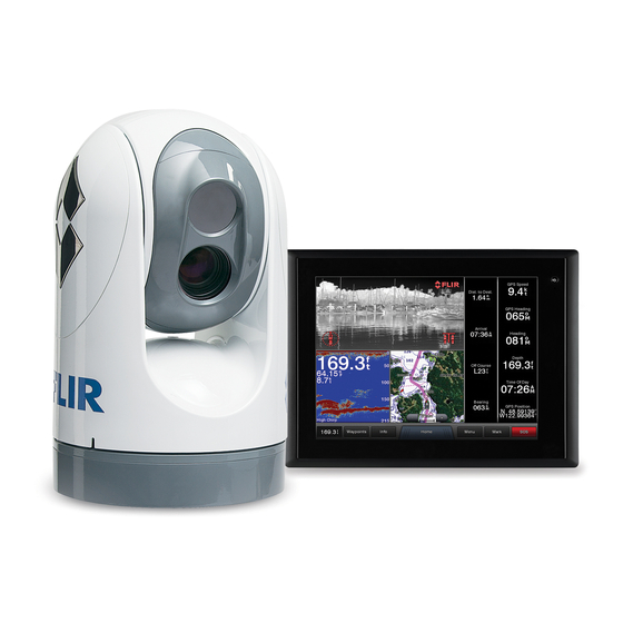
- Page 1 Integration with Garmin Displays Application Note FLIR M-Series and MD-Series Thermal Camera Garmin GPSMAP® 8000 Glass Helm Series...
-
Page 2: Table Of Contents
References ............................2 Overview ..............................3 Support ............................3 Scope ..............................3 FLIR Certified Maritime Integrator (FCMI) Training ................3 System Requirements ..........................4 Supported FLIR Camera Models ......................7 Supported Garmin GPSMAP 8000 Series ................... 7 Garmin Marine Network Considerations ..................7 Setup .............................. -
Page 3: Overview
A user may be able to control all of the camera features using certain connection options (such as the FLIR JCU), while control may be limited with other connection options, such as a smartphone app or a third-party display. -
Page 4: System Requirements
Ethernet port of the Garmin display. Damage to the camera or the display could result and will void the manufacturer’s warranty. The Ethernet interface on the FLIR M-Series camera is a PSE device and conforms to IEEE 802.3af- This powered network interface should never be 2003 specification, commonly known as PoE. - Page 5 Integration with Garmin Displays – Application Note the powered interface (marked with a red label) Similarly the FLIR PoE Injector is a PSE device and should never be connected directly to the Garmin display . The PoE Injector is commonly used to provide power to the MD-Series camera.
- Page 6 Integration with Garmin Displays – Application Note Multiple Control Devices In some installations, a FLIR JCU will be connected to the Garmin network also. Typically a Garmin GMS 10 Network Port Expander or similar device will be used as a network switch to interconnect the network...
-
Page 7: Supported Flir Camera Models
Network PoE Isolation P/N 010-10580-10. If the M-Series has a single video connection (XP models), it is recommended the video cable from the camera should be connected to the Video 1 port on the display. For M-Series cameras that have a thermal imager and a visible (lowlight or color) camera, it is generally possible to connect both video cables to the MFD and view both video images at the same time. -
Page 8: Setup
From the Video Menu, most functions that are available from the JCU are also available on the MFD. For M-Series cameras that have both thermal and visible (lowlight or color) video, the IR/Visible button can toggle between the video sources. The Change Colors button works like the Color button on the JCU, and the Change Scene button works like the Scene button on the JCU. -
Page 9: Troubleshooting
MFD to “discover” the camera. When the camera is first powered on, it will temporarily display the FLIR splash screen on the video for a few seconds, and then the video will stop again until the JCU or MFD connects to the camera and brings it out of Standby mode. - Page 10 FLIR Commercial Systems, Inc. 70 Castilian Drive Goleta, CA 93117 Phone: 888.747.FLIR (888.747.3547) International: +1.805.964.9797 www.flir.com Document Number: 432-0003-00-28-en-US Version: 110 Issue Date: July 2014...
Need help?
Do you have a question about the M-Series and is the answer not in the manual?
Questions and answers