Table of Contents
Advertisement
Quick Links
Advertisement
Table of Contents

Related Manuals for XVision EVD16NCF


Summary of Contents for XVision EVD16NCF
- Page 1 EVD16NCF 16 Channel MPEG4 DVR U U L L...
-
Page 2: Table Of Contents
Contents 1. SAFETY PRECAUTIONS.................. 3 2. FEATURES ......................4 3. PACKING LIST ....................5 4. NAME and FUNCTION of EACH PART ............6 4.1 FRONT PANEL BUTTONS and CONTROLS........6 4.2 REAR PANEL BUTTONS and CONTROLS ........7 5. INSTALLATION....................8 6. - Page 3 9. FUNCTION SETUP..................35 9.1 Main Display ..................35 9.1.1 View ....................36 9.1.2 Image Recording ................36 9.1.2.1 Save as JPEG:.................. 36 9.1.2.2 Save as AVI:..................37 9.2 Advanced Setup..................39 9.2.1 Network Setting.................. 39 9.2.2 User Setup ..................40 9.2.3 DDNS Setup ..................
-
Page 4: Safety Precautions
1. SAFETY PRECAUTIONS WARNING: This symbol is intended to alert the user to the presence of un-insulated “ dangerous voltage”. CAUTION: This symbol is intended to alert the user to presence of important operating and maintenance (Servicing) instructions in the literature accompanying the appliance. -
Page 5: Features
2. FEATURES 16-Channel video recording and 1-Channel audio recording. 1-Video outputs to monitor, 1-video output to SPOT, and 2-audio outputs. Auto NTSC/ PAL video format detection. Auto video loss detection and alarm alert. 16-Alarm signal input and 1-Relay output (auto alarm recording). High-capacity removable hard disk (up to 500 GB capacity), digital image storage replaces tape-based mechanical systems Auto overwrite or alarm notification when hard disk is full, reduces manpower... -
Page 6: Packing List
3. PACKING LIST Check and make sure all the items shown below are included in your product package. If something is missing, contact your dealer as soon as possible. Item Picture Quantity (Digital Video Recorder) Power Adaptor and Power Cord Input: AC 100~240V Output: DC 12V/4.2A Manual... -
Page 7: Name And Function Of Each Part
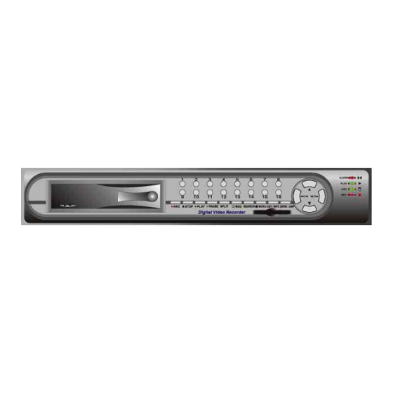
4. NAME and FUNCTION of EACH PART 4.1 FRONT PANEL BUTTONS and CONTROLS 1. Camera Select (1-16 Video Channel Button) 2. LED Indicator (Alarm/ Playback/ HDD/ Record). 3. Removable Cartridge Casing: 3.5” IDE HDD, Max.: 500 GB (optional). 4. Function Button: REC: Manual Record. -
Page 8: Rear Panel Buttons And Controls
4.2 REAR PANEL BUTTONS and CONTROLS 1. Video Input: 16-Channel BNC Input Terminal 2. DC Power Input: 12V/4.2A 3. Alarm Input/ Relay Output: DB25 Female Terminal (Please refer to appendix) 4. Audio Input: 1-Channel RCA Input Terminal 5. Speaker Output: 2-Channel BNC Output Terminal 6. -
Page 9: Installation
5. INSTALLATION 1. Connect the camera output (1 - 16) to video input (VIDEO IN) of the DVR. 2. Connect the monitor to the main monitor output (VIDEO OUT) of the DVR. 3. Connect the speaker to the speaker output (AUDIO OUT) of the DVR. 4. - Page 10 Note before operation The DVR does not support HDD hot swap function. To prevent damage, please enter main menu to stop all HDD activities, then power-off the device before replacing the hard disk. When the hard disk information icon turns to red, the device is notifying the user to replace a new hard disk.
-
Page 11: Operation Descriptions
6. OPERATION DESCRIPTIONS 6.1 LIVE MODE Press “DISP” button to switch “ON/ OFF” channel, date, and time message display. Press “INFO” to switch “ON/ OFF” system information display. When the hard disk information icon turns to red, the device is notifying the user to replace a new hard disk. -
Page 12: System Information
Full Display and Quad Display Switching Order Full Display and Quad Display Sequencing Order S Y S T E M I N F O R M A T I O N S Y S T E M V E R S I O N 0 0 B 4 3 2 5 2 9 I M A G E... -
Page 13: Record Mode
6.2 RECORD MODE Live monitoring is operable during recording. When the hard disk information icon turns to red, the device is notifying the user to replace a new hard disk. Manual Record: Under monitoring mode, press “REC” button to enable all camera recordings, and “STOP”... -
Page 14: Playback Mode
6.3 PLAYBACK MODE D O O R CAMERA TITLE PLAYBACK PAUSE REWIND FAST FORWARD STEP BACKWARD STEP FORWARD EVENT TYPE: DATE & TIME Press PLAY button, when playback password is setup to “ON”, system will request to enter a password, when correct password has been entered, all recording activities will stop. -
Page 15: Search
6.4 SEARCH Press SEARCH button, when playback password is setup to“ON”, system will request to enter a password, when correct password has been entered, all recording activities will stop. When the main password or the playback password is switched off, or the password has been copied onto the CF card, and the CF card has been inserted. -
Page 16: Menu Setup Description
7. MENU SETUP DESCRIPTION Password is requested after “MENU” button is pressed. E N T E R P A S S W O R D X X X X X X X X In order to enter the main menu, password entered must be correct. After entering the main menu all recording activities will stop. -
Page 17: Eight/ Sixteen Camera Mode Rescan
7.1 EIGHT/ SIXTEEN CAMERA MODE RESCAN When only 8 cameras has been connected (whether it is the first 8 or last 8 cameras), the system will enter 8-ch monitoring display mode. For all cameras to be displayed the system will have to reboot or enter the menu to re-detect 16-ch monitoring display mode. -
Page 18: Camera Setup
7.3 CAMERA SETUP C A M E R A S E T U P I T L E > I T L E > V I D E O A D J U S T > M O T I O N D E T E C T I O N >... -
Page 19: Edit Camera Title 9-16
7.3.2 EDIT CAMERA TITLE 9-16 E D I C A M E R A T I T L E I T L E C H 9 * * * * C H 1 * * * * C H 1 * * * * C H 1 * * * *... -
Page 20: Motion Detection
7.3.4 MOTION DETECTION 1. Select Camera Channel: 01 ~ 16 2. Select Motion Detection Sensitivity Rate: 01 ~ 05 3. Select “SET DETECTION AREA” to show the display below. 1. Blue bar shown above indicates the motion variation of the detection window, when motion event exceeds the sensitivity setup, it triggers motion detection recording. -
Page 21: Record Setup
3. Area Block Color: Yellow: Detection Block. Transparent: Non-Detection Block. 4. Press “MENU” button to select motion detection function. A. Cursor Movement: Press button to randomly move the cursor. B. Setup Motion Detection Area: (1) Press “MENU” button, select motion detection edit function: Function Description Add Cell... -
Page 22: Schedule Setup
3. DISK FULL: Overwrite: When the disk is full the system overwrites the old data (overwriting from the oldest data) Stop: When the HDD is full the system stops recording (message will be displayed). POST ALARM: Recording time after an event (Alarm/ Motion Detection) has been triggered. -
Page 23: Hard Disk Setup
3. Alarm Recording: Alarm trigger recording according to the setup of the schedule time. Optional Settings: Each hour individually setup to different recording modes, combined settings or even no settings are acceptable. During schedule recording when manual recording is applied, the system auto switches to manual recording (manual recording is the first priority recording). -
Page 24: Cf Card Setup
7.7 CF CARD SETUP S E T U P T O T A L C A P A C I T Y R E M A I N C A P A C I T Y C A R D C O P Y >... -
Page 25: Others
3. BEGIN/ END: The system will start coping according to the setup (begin and end time). 4. COPY: Select “COPY” to start copy. *When the data size selected exceeds the storage capacity of the CF card, it will start coping from the beginning and stop when CF card is full. Different channels and different events setup generates different ASF files (audio data follows its corresponding video file). -
Page 26: Password
LANGUAGE: Supports English and Chinese on-screen menus and displays. 7.8.1 PASSWORD S E T P A S S W O R D P A S S W O R D F O R P L A Y B A C K : O N S A V E P A S S W O R D C A R D ]... -
Page 27: Buzzer
7.8.2 BUZZER B U Z Z E R S E T U P B U Z Z E R : O N P E R I O D K E Y B E E P : O F F V I D E O L O S S : O N S E C... -
Page 28: Alarm Input
RELAY OUTPUT: Relay output can be connected to external sounding device or warning device. Two Types (NO/ NC) of Relay Output Setup: ON: Relay output enabled. OFF: Relay output disabled. PERIOD: Duration time of the relay output. Relay output event includes the following: 1. -
Page 29: Squence Dwell Time
7.8.5 SQUENCE DWELL TIME S E Q U E N C E D W E L L S E T U P D W E L L S E Q U E N C E 0 3 S E C S P O T M O N I T O R 0 3 S E C... -
Page 30: Network Dvr Setup
8. NETWORK DVR SETUP Before installing the Network DVR, you need to first setup an IP Address, connect it to the ADSL Modem or LAN Hub, and use IPEdit.exe to test the DVR. Note: Before using PPPoE and DDNS connection method, one must first setup an IP Address (using IPEDIT.exe). -
Page 31: Online With Dhcp Server
8.2 Online with DHCP Server Use IPEDIT.exe to find the installed Network DVR. Select this Network DVR in the Camera List Window. The default configuration will be shown on the right window. Update the IP status. Online with DHCP Server... -
Page 32: Online Without Dhcp Server
8.3 Online without DHCP Server Use IPEdit.exe to find the installed Network DVR. The Internet DVR without IP allocated by DHCP will have a default IP Address of 169.254.1.13. Select this Internet DVR on Camera List Window. The default configuration will be shown on the right window. Under DOS mode enter “IPCONFIG”... -
Page 33: Online Connection
8.4 Online Connection Start the Internet Explorer, enter the IP Address of the Network DVR into the Address field, such as 192.168.1.31 or click twice on IPEdit. Before connection, “User name” and “Password” will be requested: Default User Name: admin Default Password: 1234 8.4.1 Install ActiveX Before entering remote connection, please install ActiveX and check your... -
Page 36: Function Setup
9. FUNCTION SETUP 9.1 Main Display Best browsing resolution is 1027x768. Live Display Move the cursor inside the image range, right mouse click to display 5 function selections: • View/ Make changes on image display • Image Recording/ Record function setup •... -
Page 37: View
9.1.1 View Two types of display method: Resizable: Adjustable image size. Actual size: The actual image size. Status Bar: Reveals current status. 9.1.2 Image Recording Image Recording Setup Display: Save as JPEG: Save as picture file Save as AVI: Save as AVI animation file 9.1.2.1 Save as JPEG: •... -
Page 38: Save As Avi
9.1.2.2 Save as AVI: • No Limit: Unrestricted image storage (continuous). • Number: Image storage according to “number”. • Save interval: Image storage according to “1/10 second” (e.g.: Enter “10”, then 1 avi file is stored per second. Enter “50”, then 5 avi files are stored in 5 seconds). •... -
Page 39: B R I G H T N E S
Resolution Setting 176x144 352x288 704x576 120x160 320x240 (Pre-set Value) 640x480 Quality Setting High Middle Low (Pre-set Value) Brightness/ Contrast/ Saturation/ Sharpness - : Mini. Value STD: Pre-set Value +: Max. Value The higher values are shown to the right and descend in value as you go to the left. Configuration Advance setup (this function is applicable only to Admin). -
Page 40: Advanced Setup
9.2 Advanced Setup Only “Admin” can select “configuration” (advanced setup). 9.2.1 Network Setting Lan Setting: LAN IP address setting is the same as IPEdit. DHCP: Select item “Automatically by DHCP” to gain an IP address. DNS: Fixed IP users needs to setup an IP address, please contact your local ISP dealer. PPPoE: Connecting using ADSL, please contact your local ISP dealer. -
Page 41: User Setup
Port Select: IP sharing device enables switching port function, setup the port and enter http://XX.XXX.X.XX:8887 (as shown on the diagram above). Please restart the Video Server after the setup has been completed, Port1=80 (Pre-set Value). DDNS: To apply dynamic IP address, you may register at DDNS Server: http://www.dyndns.org To setup follow the steps below: 1. -
Page 42: Ddns Setup
Authorization: User Authorization Setting “Needed/ No Need”. New user/ Change Password: Add user or change password (Max. user = 30). Note: Under the highest resolution, for optimum effect maximum of 20 users are suggested (English/ Chinese Characters= 11). Delete User: Delete user account. Current Users: Currently registered users. -
Page 43: Troubleshooting
10. TROUBLESHOOTING Question Answer Reconnect the internet line and make Unable to detect the Network DVR sure that it properly connected and then restart the system. Check that everything is connected properly (camera or microphone). No picture and sound Reconnect everything, make sure that the signal line is properly connected and then restart the system. -
Page 44: Network Installation
11. NETWORK INSTALLATION 11.1 System Configuration Note: Before installation, connect the video input first and then power-on. 11.2 Suggested PC Equipment 1G (Above) 256M (Above) Sound Card Office System (OS) Microsoft Windows 2000/ XP Monitor Resolution 1024x768 (Above) -
Page 45: Hard Disk Information
12. HARD DISK INFORMATION Supports 3.5” ATA 2/ 3/ 4/ 5/ 6 format hard disk. Enables installation of both built-in and removable hard disk. Support high-capacity hard disk storage (up to 500 GB capacity). Hot swap function is not applicable. To prevent damage, please enter the main menu to stop all HDD activities, then power-off the device before replacing the hard disk. -
Page 46: Appendix
13. APPENDIX 13.1 DB25 Alarm Input/Relay Output Definition Definition Definition Definition Definition 13.2 List of Tested Hard Disk Drive Brand names listed below implies tested and suggested priority use. The product does not guarantee problems due to specification change, and other brands unlisted does not mean that it is incompatible. -
Page 47: Specification
14. SPECIFICATION Format NTSC / PAL Auto Detection Video Loss Auto Detection Codec MPEG4 Video Input 16 CH BNC (1.0 Vp-p. / 75 Ohms) Main Display Output 1 CH BNC (1.0 Vp-p. / 75 Ohms) Spot Display Output 1 CH BNC (1.0 Vp-p. / 75 Ohms) Input 1 CH RCA Sampling Rate... - Page 48 Network (optional) Ethernet 10/ 100 BaseT Ethernet (RJ45) Network TCP/ IP HTTP PPPoE DNS DDNS Protocol DHCP SMTP Format NTSC/ PAL Auto Detection Video Compression M-JPEG Audio Compression AC-97 Resolution Max. 640 x 480 (NTSC), 704 x 576 (PAL) Display Frame Rate Max.
- Page 49 MEMO...
Need help?
Do you have a question about the EVD16NCF and is the answer not in the manual?
Questions and answers