Table of Contents
Advertisement
Quick Links
Download this manual
See also:
User Manual
Advertisement
Table of Contents

Subscribe to Our Youtube Channel
Related Manuals for Radionics D279A


Summary of Contents for Radionics D279A
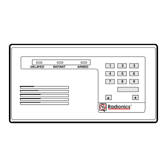
- Page 1 D279A Independent Zone Control (I.Z.C.) Operation and Installation Guide DELAYED INSTANT ARMED Radionics fi...
- Page 2 D279A D279A Operation & Installation Guide 46456B Page 2 Copyright © 2000 Radionics...
-
Page 3: Table Of Contents
Specifications ........................ 7 Features ......................... 7 Installation....................9 Connecting the D279A to the Panel ................9 Connecting the D279A to the D55 Desk Stand ............10 Operation....................11 Loop Inputs ........................11 Delayed Loop ....................... 11 Instant Loop ......................... 11 Restorals ........................ - Page 4 Figure 2: Wiring the D279A ................................ 9 Figure 3: D279A Printed Circuit Assembly ..........................13 Tables Table 1: D279A Independent Zone Control Operation and Installation Guide Organization ..........5 Table 2: Referenced Literature ..............................5 Table 3: D279A Spefications ..............................7 Table 4: Recommended D8112 Zone Codes ...........................
-
Page 5: Introduction
Other Literature Referenced See the following for a more complete and detailed description of the D279A. They have been included in the table below with their part number for easy ordering. Contact Radionics if you need to order additional literature. -
Page 6: Tips, Notes, Cautions And Warnings
If necessary, the installer should consult an experienced radio/television technician for additional suggestions, or send for the “Interference Handbook” prepared by the Federal Communications Commission. This booklet is available from the U.S. Government Printing Office, Washington D.C. 20402, stock no. 004-000-00450-7. D279A Operation & Installation Guide 46456B Page 6... -
Page 7: Overview
D279A Command Center inside the protected area. If you program the D7112, D8112, or D9112 for opening and closing reports, the D279A can initiate opening and closing reports by zone or point. A 10-wire cable is shipped with the D279A for interfacing the Independent Zone Control with the panel (4-wires), protective loops (3-wires) and onboard relay (3-wires). - Page 8 D279A Overview Notes: D279A Operation & Installation Guide 46456B Page 8 Copyright © 2000 Radionics...
-
Page 9: Installation
Installation You can mount the D279A directly onto a wall, install it in a flush-mount unit, or attach it to a D55 Desk Stand (see the special installation instruction sheet that comes with each item). Do not mount the D279A in a location exposed to direct sunlight. -
Page 10: Connecting The D279A To The D55 Desk Stand
Place the enclosure base on the wall in the desired location, and mark the locations of the mounting holes. (The base can be mounted to a single-gang wall box. The two mounting screw holes in the base of the D279A are positioned for standard single-gang compatibility.) Secure the enclosure base to the wall or gang box. -
Page 11: Operation
Entry/Exit Delay Both loops must be normal before the D279A can be armed. When you enter your passcode, an exit delay of 60 seconds is provided before the unit arms. When the IZC (Independent Zone Control) is armed, faulting the delayed loop starts an entry delay of 30 seconds. -
Page 12: Buzzer
During entry delay, the buzzer sounds steadily until an alarm occurs or the D279A is disarmed. If you press a numbered key while the D279A is disarmed and a loop is faulted, the buzzer indicates that the D279A is not ready to arm. -
Page 13: Programming
Programming or Changing the Passcode A four digit passcode is used to arm and disarm the D279A. This code can be changed only by first knowing the existing (old) passcode. Change the passcode only while the D279A is DISARMED, and BOTH protective loops are normal. -
Page 14: Programming The D8112 Panel Protective Zone
Opening and closing reports by zone: When using the D279A to send opening and closing reports by zone, do not use the same number for the D279A zone number as you do for the passcode ID or the reporting number (see 8112:MAIN Program Entry Guide , section 8. -
Page 15: Programming The D7112 Panel Point
W1 jumper: For normal operation with the D4112 or D6112, do NOT cut jumper W1. However, if you want to display the D279A armed or disarmed status at the D4112 or D6112 command center, or if you want to put the D279A on a priority zone, cut jumper W1. - Page 16 If programming the D279A with 9000 Series C panels, you can use Point Index 17 (O/C non-priority) or Point Index 18 (O/C priority) to program points for use with the D279A. Cut the W1 jumper on the D279A to send Point Opening and Point Closing reports.
Need help?
Do you have a question about the D279A and is the answer not in the manual?
Questions and answers