Foxconn NanoPC User Manual
Hide thumbs
Also See for NanoPC:
- User manual (22 pages) ,
- Easy manual (2 pages) ,
- User manual (21 pages)
Table of Contents
Advertisement
Quick Links
Advertisement
Table of Contents

Related Manuals for Foxconn NanoPC


Summary of Contents for Foxconn NanoPC
- Page 1 NanoPC...
- Page 2 Symbol description: Note: Refers to important information that can help you to use NanoPC better, and tells you how to avoid problems. Caution: Indicating a potential risk of hardware damage or physical injury may exist.
- Page 3 Safety Notice: Before using this product, please read the below safety notice carefully, this will help to extend the product’s lifecycle, and work normally. The power adapter is dissipating heat during normal use, please be sure not to cover ...
- Page 4 Package Contents NanoPC Seat Base VESA Mount Power A dapter Power Cord Opening Tool Screws, Magnet Rubber Foot, Mini PCIe Half Card Support Mini COM to COM cable (Optional) Screws cover...
-
Page 5: Table Of Contents
1-2 Back Side View ....................... 4 ..................... 6 Placement and connecting 2-1 Placement of NanoPC ................... 8 In Seat Base ......................8 On the desk ......................8 ....................9 2-2 ... - Page 6 Fox Intelligent Stepping ..................20 ....................21 Advanced ........................23 Trusted Computing ....................24 North Bridge ......................25 TXE Subsystem ...................... 26 ................27 ....................28 ................... 29 ...
-
Page 7: Introduction
Introduction... -
Page 8: 1-1 Front Side View
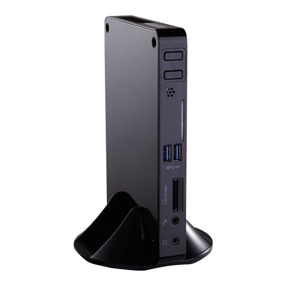
1-1 Front Side View... - Page 9 states. Suspend Button Enter suspend mode in operating system. Clear CMOS : Press Suspend Button 10s in S5. USB 3.0 port hard disk drives, etc. Multi-Function card reader memory cards used in devices like digital cameras, mobile phones, Media players and so on.
-
Page 10: 1-2 Back Side View
1-2 Back Side View... - Page 11 devices. Kensington lock Attach a Kensington security system or a compatible security lock to secure your NanoPC in place. Connect network cable to access Internet. Connects to powered analog speakers or recording devices with optical connectors (3.5mm jack).
- Page 12 1-3 DDR3/DDR3L jumper 1.35V 1.5V...
-
Page 13: Placement And Connecting
Placement connecting... -
Page 14: 2-1 Placement Of Nanopc
2-1 Placement of NanoPC In Seat Base 1. Place your NanoPC into the groove of the Seat Base On the desk 1. Fit your NanoPC with Magnet Rubber Foot, and put it on the tabletop directly. - Page 15 Installing to Display This is the best space-saving way. 1. Use four screws to fasten the Vesa Mount onto the display back. 2. Fit the Nettop into the Vesa Mount with power button locating at the top for easy touch. ...
-
Page 16: 2-2 Connection Of Nanopc
2-2 Connection of NanoPC Connect display ... -
Page 17: Connect Usb Devices
Connect USB devices Connect USB devices to the USB ports, for example, mouse, keyboard devices. Connect network cable switch. -
Page 18: Connect Power Cord
Connect power cord Connect the power adapter to the power input port of the NanoPC, and then press the power button to start it. The power adapter is dissipating heat during normal use, please do not cover it and ... -
Page 19: Connect Point Of Sales
Connect Point Of Sales Connect one end of cable to the COM port, and the other end to a Point Of Sales. ... -
Page 20: Bios Setup
BIOS Setup... -
Page 21: Enter Bios Setup
BIOS SETUP Enter BIOS Setup The BIOS is the communication bridge between hardware and software, correctly setting up the BIOS pa- rameters is critical to maintain optimal system performance. Power on the computer, when the message We do not suggest that you change the default values in the BIOS Setup, and we shall not be responsible for any damage which resulted from the change you made. - Page 22 BIOS SETUP optimal default may sometimes come out an unstable system. What you need now is to adjust BIOS save or discard the changes and exit BIOS setup here.
-
Page 23: Main
BIOS SETUP Main Main F-center Advanced Boot Power Health Security Save&Exit System Date [Sun 01/06/2013] Set the Date. Use Tab System Time [09:37:57] to switch between Date elements. Access Level Administrator Model Name nT-iBT18/-iBT19/-iBT29 TXE Version 01.00.02.1060 EC Version D72F1116 BIOS Version D72F1D14 x64 Build Date and Time... -
Page 24: F-Center
BIOS SETUP no password is set or you enter system with administrator password, this item will display F-center Main F-center Advanced Boot Power Health Security Save&Exit Super BIOS Protect [Disabled] Super BIOS Protection Settings. Smart BIOS Fox Intelligent Stepping CPU Configuration : Select Screen ↑... -
Page 25: Smart Bios
BIOS SETUP Smart BIOS Main F-center Advanced Boot Power Health Security Save&Exit Smart Power LED [Disabled] Smart Power LED Smart Boot Menu [Enabled] Settings : Select Screen ↑ ↓/Click: Select Item Enter/Dbl Click: Select +/-: Change Opt. F1: General Help F2: Previous Values F3: Optimized Defaults F4: Save &... -
Page 26: Fox Intelligent Stepping
BIOS SETUP password trying to get into your computer through smart boot menu. Fox Intelligent Stepping Main F-center Advanced... - Page 27 BIOS SETUP Main F-center Advanced Boot Power Health Security Save&Exit CPU Configuration XD can prevent certain classes of malicious CPU Brand Name: buffer overflow attacks Intel(R) Celeron(R) CPU J1900 @ 1.99GHz when combined with a L1 Data Cache 24 KB X 4...
- Page 28 BIOS SETUP - You can select the EIST (Processor Power Management, PPM) through this item. adjust processor voltage and core frequency, which can result in decreased average power consumption and decreased average heat production. There are some system requirements must be met, including CPU, chipset, motherboard, BIOS and operation system.
-
Page 29: Advanced
BIOS SETUP Advanced Main F-center Advanced Boot Power Health Security Save&Exit Trusted Computing Trusted Computing North Bridge Settings TXE Subsystem Onboard Device Configuration SATA Configuration Super IO Configuration Network Stack Realtek PCIe GBE Family Controller (MAC:00:00:00:00:00:03) : Select Screen ↑ ↓/Click: Select Item Enter/Dbl Click: Select +/-: Change Opt. -
Page 30: Trusted Computing
BIOS SETUP Trusted Computing Main F-center Advanced Boot Power Health Security Save&Exit Configuration Enables or Disables Security Device Support [Disabled] BIOS support for security device. -
Page 31: North Bridge
BIOS SETUP North Bridge Main F-center Advanced Boot Power Health Security Save&Exit North Bridge Configuration Select DVMT 5.0 Pre- Allocated (Fixed) Memory Information Graphics Memory size Total Memory 2048 MB (DDR3/DDR3L 1333) -
Page 32: Txe Subsystem
BIOS SETUP TXE Subsystem Main F-center Advanced Boot Power Health Security Save&Exit Intel TXE Subsystem Configuration TXE Version 01.00.02.1060 : Select Screen ↑... - Page 33 BIOS SETUP Main F-center Advanced Boot Power Health Security Save&Exit Onboard Device Configuration Enabled/Disabled board LAN Control- Onboard LAN Controller [Enabled] Onboard USB Controller [Enabled] Legacy USB Support [Enabled] USB3.0 Support [Enabled] Azalia HD Audio controller [Enabled] : Select Screen ↑...
- Page 34 BIOS SETUP Main F-center Advanced Boot Power Health Security Save&Exit...
- Page 35 BIOS SETUP Main F-center Advanced Boot Power Health Security Save&Exit Super IO Configuration Set Parameters of Serial Port 1 Super IO Chip IT8518E/IT8519E (COMA) Serial Port 1 Configuration : Select Screen...
- Page 36 BIOS SETUP Main F-center Advanced...
-
Page 37: Boot
BIOS SETUP Boot Main F-center Advanced Boot Power Health Security Save&Exit Boot Configuration Select the keyboard Bootup Numlock State [On] NumLock state Quiet Boot [Enabled] Fast Boot [Disabled]... -
Page 38: Csm Parameters
BIOS SETUP This items appear only when the devices are available. Use this items to specify the boot device priority sequence of the detected devices. CSM parameters Main F-center Advanced... -
Page 39: Power
BIOS SETUP Power Main F-center Advanced Boot Power Health Security Save&Exit Resume By USB Resume By USB Device(s) [Enabled] Device(s) Resume By Onboard LAN [Disabled] Resume By RTC [Disabled]... -
Page 40: Health
BIOS SETUP This item is used to set which state the PC will take with when it resumes after an A C power loss. Health Main F-center Advanced Boot Power Health Security Save&Exit CPU Temperature : +40 ˚C CPU Shutdowm CPU Fan Speed : 3326 RPM... -
Page 41: Security
BIOS SETUP Security Main F-center Advanced Boot Power Health Security Save&Exit Set Administrator Security configuration Password Administrator Password Not Installed User Password Not Installed Administator Password Secure Boot menu : Select Screen ↑ ↓/Click: Select Item Enter/Dbl Click: Select +/-: Change Opt. F1: General Help F2: Previous Values F3: Optimized Defaults... -
Page 42: Save & Exit
BIOS SETUP Save & Exit Main F-center Advanced Boot Power Health Security Save&Exit Save Changes and Reset Reset the system af- Discard Changes and Reset Restore Defaults saving the changes. Boot Override Windows Boot Manager (P1: WDC WD2500BEVT-22A23T0) UEFI: General USB Flash Disk 1.0 UEFI: SMI USB DISK 1100 UEFI: Built-in EFI Shell Reset System with ME disabled Mode... - Page 43 BIOS SETUP By this default, BIOS have set the optimal performance parameters of system to improve the performances of system components. But if the optimal performance parameters to be set cannot be supported by your hardware devices (for example, too many expansion cards were installed), the system might fail to work.
-
Page 44: Install Os
Install OS Windows 7(64 bit) - Page 45 What kinds of hardware and software you need here: 4-1 Install Windows 8.1/Windows 8/Windows 7(64 bit) 1. Connect the Windows one USB port of NanoPC. 2. Press power on button to turn on your computer. for installing the OS. Windows.
- Page 46 8. The setup will display the hard disk partitions (20GB, in this example) of your system. If there were hard drive.
- Page 47 To ensure that all Windows features work correctly, Windows might create additional partitions for ...
- Page 49 or you can click on each individual driver to install it manually. When you install the driver of Windows 4. After installing all the drivers, you need to restart your NanoPC, then you can start using it.
-
Page 50: Utility
Utility... - Page 51 Fox WINFLASH Supporting Operating Systems: 1. Local Update This page lets you know your system BIOS information. Minimum Exit Toolbar Show current BIOS information Please refer to the physical motherboard for details. ...
- Page 52 that you may need them to recover your BIOS later. Key in a BIOS name Click to Save ...
-
Page 53: 2. About & Help
2. About & Help... - Page 54 Statement: This device complies with part 15 of the FCC Rules. Operation is subject to the following two conditions: (1) This device may not cause harmful interference, and (2) this device must accept any ...
- Page 55 Warning statement for Europe: Hereby, Foxconn, declares that this nT-iBT Series is in compliance with the essential requirements ...
Need help?
Do you have a question about the NanoPC and is the answer not in the manual?
Questions and answers