Table of Contents
Advertisement
Advertisement
Table of Contents

Related Manuals for Foxconn NanoPC nT-i2000 Series


Summary of Contents for Foxconn NanoPC nT-i2000 Series
- Page 1 NanoPC User’s Manual...
-
Page 2: Symbol Description
Trademark: All trademarks are the property of their respective owners. Version: User’s Manual V1.1 for nT-i2000 series NanoPC. Symbol description: Caution : refers to important information that can help you to use NanoPC bet- ter, and tells you how to avoid problems. -
Page 3: Safety Notice
Safety Notice : Before using this product, please read the below safety notice carefully, this will help to extend the product’s lifecycle, and work normally. ■ When NanoPC is working, please make sure its ventilation system is working. ■ The power adapter is dissipating heat during normal use, please be sure not to cover it and keep it away from your body to prevent discomfort or injury by heat exposure. -
Page 4: Table Of Contents
TABLE OF CONTENTS Chapter 1 Introduction of NanoPC Top View ....................2 Front Side View ..................2 Back Side View ..................3 Bottom View .....................3 Chapter 2 Placement and connection of NanoPC Placement of NanoPC On the Desk ..................5 On the Display Back ................5 Connection of NanoPC Connect the Monitor ................7 Connect the USB Devices ..............7... - Page 5 Accessory List Thanks for choosing our products. Please check the accessories listed below. If there is any- thing broken or lost, please contact with your distributors as soon as possible. Power Adapter Power Cord Magnet Rubber Foot Vesa Mount Seatbase Opening Tool 9.70mm Screw for VESA Mounting...
- Page 6 This chapter introduces NanoPC’s outlook : ■ Top View ■ Front Side View ■ Back Side View ■ Bottom View...
-
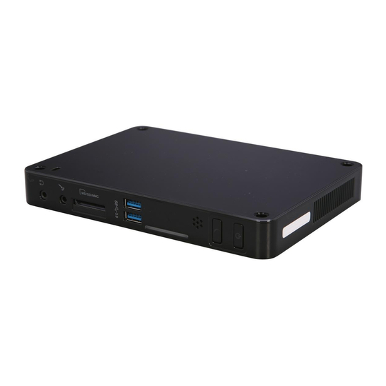
Page 7: Top View
1-1 Top View (190mm) 7.5in Name Description Kensington Lock Attach a Kensington security system or a compatible lock to secure your NanoPC 1-2 Front Side View Name Description Headphone Port Connects to a headphone Microphone In and S/PDIF In Connects to a microphone or playback devices with Port optical connectors(3.5mm jack) Multi-Function Card Reader... -
Page 8: Back Side View
1-3 Back Side View Name Description USB 2.0 Ports Connects to USB devices Display Output Port (VGA) Connects to display device HDMI Port Connects to HDMI audio and video Network Port Standard RJ-45 network port Line Out and S/PDIF Out Port Connects to powered analog speakers or record- ing devices with optical connectors(3.5mm jack) Power Input Port... - Page 9 In this chapter, the placement and the connection of some neces- sary peripherals will be introduced. This chapter includes the following information: ■ Placement of NanoPC ■ Connection of NanoPC...
-
Page 10: Placement Of Nanopc
2-1 Placement of NanoPC 1. On the Desk 1.1. You can install your NanoPC in the Seatbase like the right image. 1.2. If there is enough space on your desk, you can simply put your NanoPC on the tabletop as shown below. 2. - Page 11 2.2. Fit the NanoPC into the Vesa Mount with power button locating at the top for easy touch. Lift up the NanoPC straightly to take it out.
-
Page 12: Connection Of Nanopc
2-2 Connection of NanoPC 1. Connect the Monitor Connect a monitor to the NanoPC through VGA connector. 2. Connect the USB Devices Connect USB devices to the USB ports of the NanoPC, for example, mouse and keyboard. 3. Connect the Network Cable Connect LAN cable to the RJ-45 port, with the other end connected to a hub or switch. -
Page 13: Connect The Power Cord
4. Connect the Power Cord Connect the power adapter to the power input port of the NanoPC, and push the power button to start it. Outlet The power adapter is dissipating heat during normal use, please make sure not to cover it and keep it away from your body to prevent discomfort or injury from heat exposure. -
Page 14: Chapter 3 Bios Setup
This chapter tells how to change system settings through the BIOS Setup menus. Detailed descriptions of the BIOS parameters are also provided. You have to run the Setup Program when the following cases occur : 1. An error message appears on the screen during the system Power On Self Test (POST) process. -
Page 15: Enter Bios Setup
Enter BIOS Setup The BIOS is the communication bridge between hardware and software, correctly setting up the BIOS parameters is critical to maintain optimal system performance. Power on the computer, when the message "Press <Del> to enter setup, <F11> Display Boot Menu" appears at the bot- tom of the screen, you can press <DEL>... -
Page 16: Main
Main Menu The BIOS Setup is accessed by pressing the <Del> button after the Power-On Self-Test (POST) memory test begins and before the operating system boot begins. Once you enter the BIOS Set- up Utility, the Main Menu will appear on the screen. The Main Menu provides System Overview information and allows you to set the System Time and Date. -
Page 17: Advanced
Advanced Aptio Setup Utility - Copyright (C) 2012 American Megatrends, Inc. Main Advanced Power Security BootOptions Save & Exit Advanced ▶ Miscellaneous Miscellaneous ▶ Integrated Periperals ▶ SATA Configuration ↑ ↓→ ←: Move Enter: Select +/-: Change Opt ESC: Exit F1: General Help F2: Previous Values F3: Optimized Defaults... -
Page 18: Integrated Peripherals
Integrated Peripherals Aptio Setup Utility - Copyright (C) 2012 American Megatrends, Inc. Main Advanced Power Security BootOptions Save & Exit Advanced Enable/Disable Onboard USB3.0 USB Configuration Onboard USB3.0 Controller [Enabled] Controller. PCH Azalia Configuration Azalia [Enabled] ↑ ↓→ ←: Move Enter: Select +/-: Change Opt ESC: Exit... -
Page 19: Sata Configuration
SATA configuration Aptio Setup Utility - Copyright (C) 2012 American Megatrends, Inc. Main Advanced Power Security BootOptions Save & Exit Advanced Enable/Disable SATA Device. SATA Controller(s) [Enabled] SATA Mode Selection [AHCI] ↑ ↓→ ←: Move Enter: Select +/-: Change Opt ESC: Exit F1: General Help F2: Previous Values... -
Page 20: Power
Power Aptio Setup Utility - Copyright (C) 2012 American Megatrends, Inc. Main Advanced Power Power Security BootOptions Save & Exit Set the restore on AC power loss function Restore On AC Power Loss [Last state] Deep Sleep Support [Enabled] ↑ ↓→ ←: Move Enter: Select +/-: Change Opt ESC: Exit... - Page 21 Power Aptio Setup Utility - Copyright (C) 2012 American Megatrends, Inc. Main Advanced Power Power Security BootOptions Save & Exit Select ACPI sleep state the system will en- Restore On AC Power Loss [Last state] ter when the SUSPEND button is pressed. Deep Sleep Support [Disabled] Lan Wakeup...
-
Page 22: Security
Security Aptio Setup Utility - Copyright (C) 2012 American Megatrends, Inc. Main Advanced Power Security Security BootOptions Save & Exit Valid Keys: Administrator Password Status Not Installed (1)a-z (A-Z) User Password Status Not Installed (2)0~9 (3)11 special keys:-=[];,./ Change Supervisor Password (2)key pad:0-9 support and 5 special keys ME Flash Write Protect... -
Page 23: Bootoptions
BootOptions Aptio Setup Utility - Copyright (C) 2012 American Megatrends, Inc. Main Advanced Power Security BootOptions Save & Exit BootOptions Launch CSM [Enabled] This item controls if CSM will be launche. WARNING: This option is for advanced Launch PXE OpROM policy [Do not launch] users. -
Page 24: Save & Exit
Save & Exit Aptio Setup Utility - Copyright (C) 2012 American Megatrends, Inc. Main Advanced Power Security BootOptions Save & Exit Save & Exit Save Changes and Exit Exit system setup after saving Discard Changes and Exit the changes. Save Changes Discard Changes Load Default Values Save as User Default Values... - Page 25 ► Load User Default Values If you select this option and press <Enter>, a message will be displayed in the screen. Select [Yes] to restore/load the user defaults to all the setup options, select [No] or <ESC> to return to the menu.
-
Page 26: Chapter 4 Install Windows Os
This chapter introduces the following information: ■ Install Windows 7/8 ■ Install Drivers in Windows 7/8... -
Page 27: Install Windows 7/8
F3: Optimized Defaults F4: Save & Exit Setup F7: Load User-defined Defaulta F8: Save as User-defined Version 2.15.1231. Copyright (C) 2002-2012 Foxconn, Inc. 4. The computer will reboot, and it will start loading files for installing Windows 7/8 Operating System. - Page 28 5. After that, it will start Windows and come out a “Install Windows” dialog box to set the “Lan- guage to install”, “Time and current format” and “ Keyboard or input method”. Click “Next” to continue and click “Install now” button to start the setup. 6.
- Page 29 9. In this biggest hard disk size screen, you can click “New” button to create partitions as you need. In this example, we will create a 70GB partition to install Windows, and click “Apply”. To ensure that all Windows features work correctly, Windows might create an additional parti- tions for system files, so you will see a system reserved partition.
- Page 30 10. From this step we start to install Windows 7/8 into your hard disk, including copying Win dows files, expanding Windows files...etc. During the installation, your computer will restart several times. 11. When the installation is completed, setup will prepare your compute for the first use. Then you can follow steps to select system settings, create an account, set a password...etc, until the whole process is completed and enter Windows 7/8 Operating System.
-
Page 31: Install Drivers In Windows 7/8
Install Drivers in Windows 7/8 1. When the Windows 7/8 is completely installed, you have to install the necessary drivers before using the NanoPC. Connet the USB Flash Disk.(USB Flash Disk is in this package) 2. Waiting for a few seconds, the main menu will be displayed, click “Driver” to enter the Driver menu shown as below: 3. - Page 32 This chapter introduces the following information: ■ FOX WinFlash...
-
Page 33: Fox Winflash
FOX WinFlash FOX WinFlash is a useful utility to backup and update your system BIOS. Supporting Operating Systems : ■ Windows XP (32-bit/64-bit) ■ Windows 7 (32-bit/64-bit) ■ Windows 8 (32-bit/64-bit) Using FOX WinFlash: 1. Local Update 1-1 Local Update - BIOS Information This page lets you know your system BIOS information. - Page 34 1-2 Local Update - Backup This page can back up your system BIOS. You can click “Backup BIOS”, and key in a file name, then click “Save” to finish the backup operation. The extension of this backup file is “.ROM” for AMI BIOS.
-
Page 35: About & Help
2. About & Help This page shows some information about FOX WinFlash. Show information about FOX WinFlash... - Page 36 Also, put in the manual which directive to fulfil and also which countries to sell the product. Example of a text to tell which directive has been fulfilled: Hereby, Foxconn, declares that this nT-i2000 series is in compliance with the essential requirements and other relevant provisions of Directive 1999/5/EC.”...
Need help?
Do you have a question about the NanoPC nT-i2000 Series and is the answer not in the manual?
Questions and answers