Table of Contents
Advertisement
Advertisement
Table of Contents

Subscribe to Our Youtube Channel
Related Manuals for Foxconn nT-A3550


Summary of Contents for Foxconn nT-A3550
- Page 1 nT-A3000 Series Nettop User’s Manual...
-
Page 2: Symbol Description
Trademark: All trademarks are the property of their respective owners. Version: User’s Manual V1.0 for nT-A3000 Series Nettop. P/N: 3A223A900-000-G Symbol description: Caution : refers to important information that can help you to use NETTOP better, and tells you how to avoid problems. WEEE: The use of this symbol indicates that this product may not be treated as household waste. - Page 3 Safety Notice : Before using this product, please read the below safety notice carefully, this will help to extend the product’s lifecycle, and work normally. ■ When NETTOP is working, please make sure its ventilation system is working. ■ The power adapter is dissipating heat during normal use, please be sure not to cover it and keep it away from your body to prevent discomfort or injury by heat exposure.
-
Page 4: Table Of Contents
TABLE OF CONTENTS Chapter 1 Introducing the NETTOP Top View View ....................2 Front Side View View ..................2 Back Side View View ..................3 Bottom View Bottom View .....................3 Chapter 2 Placing and connecting the NETTOP Placement of NETTOP On the Desk ..................5 On the Display Back ................5 Connection of NETTOP Connect the Monitor... - Page 5 Accessory List Thanks for choosing our products. Please check the accessories listed below. If there is anything broken or lost, please contact with your distributors as soon as possible. DVI to VGA Adapter Power Adapter Power Cord magnet rubber foot Vesa mount Seatbase Opening Tool...
-
Page 6: Top View View
This chapter introduces NETTOP’s outlook : ■ Top View ■ Front Side View ■ Back Side View ■ Bottom View... -
Page 7: Front Side View View
1-1 Top View 190mm Name Description Kensington Lock Attach a Kensington security system or a compatible lock to secure your Nettop 1-2 Front Side View Name Description Headphone Port Connects to a headphone Microphone In and S/PDIF In Connects to a microphone or playback devices with Port optical connectors(3.5mm jack) Multi-Function Card Reader... -
Page 8: Back Side View View
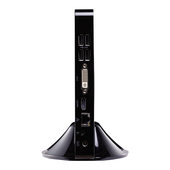
1-3 Back Side View Name Description USB 2.0 Ports Connects to USB devices Display Output Port Connects to display device HDMI Port Connects to HDMI audio and video Network Port Standard RJ-45 network port Line Out and S/PDIF Out Port Connects to powered analog speakers or record- ing devices with optical connectors(3.5mm jack) Power Input Port... -
Page 9: Placement Of Nettop
In this chapter, the placement and the connection of some neces- sary peripherals will be introduced. This chapter includes the following information: ■ Placement of NETTOP ■ Connection of NETTOP... -
Page 10: On The Desk
2-1 Placement of NETTOP 1. On the Desk 1.1.You can install your NETTOP in the mount like the right image. 1.2. If there is enough space on your desk, you can simply put your NETTOP on the tabletop as shown below. 2. - Page 11 2.2. Fit the NETTOP into the bracket with power button locating at the top for easy touch. Lift up the NETTOP straightly to take it out.
-
Page 12: Connection Of Nettop
2-2 Connection of NETTOP 1. Connect the Monitor Connect a monitor to the NETTOP through DVI connector. 2. Connect the USB Devices Connect USB devices to the USB ports of the NETTOP, for example, mouse and keyboard. 3. Connect the Network Cable Connect LAN cable to the RJ-45 port, with the other end connected to a hub or switch. -
Page 13: Power Cord
4. Connect the Power Cord Connect the power adapter to the power input port of the NETTOP, and push the power but ton to start it. Outlet The power adapter is dissipating heat during normal use, please make sure not to cover it and keep it away from your body to prevent discomfort or injury from heat exposure. -
Page 14: Chapter 3 Bios Setup
This chapter tells how to change system settings through the BIOS Setup menus. Detailed descriptions of the BIOS parameters are also provided. You have to run the Setup Program when the following cases occur : 1. An error message appears on the screen during the system Power On Self Test (POST) process. -
Page 15: Enter Bios Setup
Enter BIOS Setup The BIOS is the communication bridge between hardware and software, correctly setting up the BIOS parameters is critical to maintain optimal system performance. Power on the computer, when the message "Press <DEL> or <F2> to enter setup, Press <F9> to enter boot menu" appears at the bottom of the screen, you can press <DEL>... -
Page 16: Main
Main The BIOS Setup is accessed by pressing the <DEL> or <F2> button after the Power-On Self-Test (POST) memory test begins and before the operating system boot begins. Once you enter the BIOS Setup Utility, the Main Menu will appear on the screen. The Main Menu provides System Overview information and allows you to set the System Time and Date. - Page 17 Memory Information ► Total Memory This item displays the total memory size. The size is depending on how many memory mod- ules are installed in your system before powering on. ► System Date <weekday><month><date> <year> format. Day—weekday from Sun. to Sat., this message is automatically displayed by BIOS (Read Only).
-
Page 18: Advanced
Advanced Aptio Setup Utility - Copyright (C) 2010 American Megatrends, Inc. Main Advanced Boot Security Save & Exit Advanced Select the SATA Mode SATA Mode [AHCI Mode] Deep Sleep Support [Enabled] Option: USB 2.0 Port S3 Wakeup [Enabled] (1) IDE Mode LAN / USB 3.0 Port S3 Wakeup [Enabled] (2) AHCI Mode... - Page 19 ► Supporting C6 power Loss This item is used to enable or disable C6 power state,which is featured in Fusion processors. ► Integrated GPU UMA Frame Buffer This item is used to set Integrate Graphics UMA Frame Buffer Size.
-
Page 20: Boot
Boot Aptio Setup Utility - Copyright (C) 2010 American Megatrends, Inc. Main Advanced Boot Security Save & Exit Boot Boot Configuration select the keyboard numlock state Bootup Numlock State [On] Quiet Boot [Disabled] Fast Boot [Disabled] Set Boot Priority 1st Boot [USB CD/DVD] 2nd Boot [Hard Disk: WDC WD1...]... - Page 21 Hard Disk Drive BBS Priorities Aptio Setup Utility - Copyright (C) 2010 American Megatrends, Inc. Boot Boot Hard Disk Drive BBS Priorities Set Boot Priority 1st Boot [SATA:WDC Wd1600BE...] → ←: Select Screen ↑ ↓: Select Item Enter: Select +/-: Change Opt. F1: General Help F2: Previous Values F3: Optimized Defaults...
-
Page 22: Security
Security Aptio Setup Utility - Copyright (C) 2010 American Megatrends, Inc. Main Advanced Boot Save & Exit Security Set Setup Administrator Password Password Description If ONLY the Administrator’s password is set, then this only limits access to Setup and is only asked for when entering Setup. -
Page 23: Save & Exit
Save & Exit Aptio Setup Utility - Copyright (C) 2010 American Megatrends, Inc. Main Advanced Boot Security Save & Exit Save & Exit Exit system setup after saving Save Changes and Exit the changes. Discard Changes and Exit Save Changes and Reset Discard Changes and Reset Save Options Save Changes... - Page 24 Select this option and press Enter, it will pop out a dialogue box to let you load the defaults. Select <Yes> and then press <Enter> to load the defaults. Select <No> and press <Enter>, it will not load. By this default, BIOS have set the optimal performance parameters of system to improve the performances of system components.
-
Page 25: Install Windows 7
This chapter introduces the Windows installation : ■ Install Windows 7 ■ Install Drivers in Windows 7... - Page 26 Make sure you have these ready : 1. NETDVD. (It is an optional accessory. If there is no NETDVD in this package, you need other purchase an external USB DVD-ROM drive.) 2. NETTOP driver CD. (In this package) 3. Windows 7 Install CD. (Other purchase) Before we continue : ■...
- Page 27 4. The computer will reboot, and it will start loading the files for installing the Windows 7 Operating System. 5. After the computer reboots it will start loading the files for installing Windows 7. Click “Next” to continue and click “Install now” button to start the setup. 6.
- Page 28 9. In the hard disk size screen, you can click the “new” button to create partitions as you need. In this example we are creating a 70GB partition to install Windows. Make your modifications and click “Apply”. To ensure that all Windows features work correctly, Windows might create additional partitions for system files.
- Page 29 10. The setup program will then start to install Windows 7 on your hard disk. During the installa tion, your computer will restart several times. 11. When the installation is complete, setup will prepare your computer for it’s first use. You can then follow the steps to select system settings, create an account, set a password...etc, until the whole process is complete.
- Page 30 4-2 Install Drivers in Windows 7 1. When the Windows 7 is completely installed, you have to install the necessary drivers before using the NETTOP. Take out the Windows 7 Install CD from the USB DVD-ROM drive, and put the NETTOP driver CD inside. 2.
- Page 31 Also, put in the manual which directive to fulfil and also which countries to sell the product. Example of a text to tell which directive has been fulfilled: Hereby, Foxconn, declares that this nT-A3000 series is in compliance with the essential requirements and other relevant provisions of Directive 1999/5/EC.”...
Need help?
Do you have a question about the nT-A3550 and is the answer not in the manual?
Questions and answers