Advertisement
Quick Links
NB3N1200KMNGEVB,
NB3W1200LMNGEVB
NB3N1200K/NB3W1200L
Evaluation Board
User's Manual
Introduction
The NB3N1200KMNGEVB and the NB3W1200LMNG
EVB evaluation boards were developed with a common
PCB layout design to accommodate the NB3N1200K
(standard HCSL outputs) and the NB3W1200L (HCSL
Push-Pull outputs) devices. Each board comes fully
assembled and tested and is ready to evaluate in the lab. This
evaluation board was designed to provide a flexible and
convenient platform to quickly evaluate, characterize and
verify the operation of the NB3N1200K or NB3W1200L
devices. To minimize the board size, six differential outputs
are accessed with SMA connectors. The other six
differential outputs are loaded, terminated and can be
monitored with a high impedance probe as explained later in
the manual.
The NB3N1200K Evaluation Board schematic is the
same as the NB3W1200L schematic except the "1200L" has
some components depopulated (DNI) per the "1200L"
BOM.
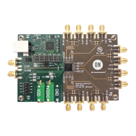
Top View
Figure 1. NB3N1200KMNGEVB and NB3W1200LMNGEVB Evaluation Board
© Semiconductor Components Industries, LLC, 2013
December, 2013 − Rev. 0
EVAL BOARD USER'S MANUAL
•
The NB3W1200LMNGEVB does not have RP resistors
installed on its differential Push-Pull outputs.
•
The NB3W1200LMNGEVB does not have
FB_OUT/FB_OUT# resistors installed.
•
The NB3W1200LMNGEVB does not have R
resistor R107 installed.
This manual should be used in conjunction with the device
datasheet which contains full technical details on the device
specifications and operation.
This evaluation board manual contains:
•
Information on the NB3N1200K/NB3W1200L
Evaluation Board
•
Assembly Instructions
•
Test and Measurement Setup Procedures
•
Board Schematic and Bill of Materials
Bottom View
1
http://onsemi.com
REF
Publication Order Number:
EVBUM2216/D
Advertisement

Subscribe to Our Youtube Channel
Related Manuals for ON Semiconductor NB3N1200KMNGEVB


Summary of Contents for ON Semiconductor NB3N1200KMNGEVB
- Page 1 Board Schematic and Bill of Materials some components depopulated (DNI) per the “1200L” BOM. Top View Bottom View Figure 1. NB3N1200KMNGEVB and NB3W1200LMNGEVB Evaluation Board © Semiconductor Components Industries, LLC, 2013 Publication Order Number: December, 2013 − Rev. 0 EVBUM2216/D...
- Page 2 NB3N1200KMNGEVB, NB3W1200LMNGEVB QUICK START LAB SET-UP USER’S GUIDE Pre-Power-Up Table 1. POWER SUPPLY CONNECTIONS 1. The NB3N1200K and NB3W1200L have positive Device Pin power supply pins VDD and VDDIO. Connect Power Supply Connector Power Supply power supply cables to VDD, VDDIO and GND 3.3 V...
- Page 3 NB3N1200KMNGEVB, NB3W1200LMNGEVB Power Supplies Control Pins Each VDD, VDDIO and GND power supply has Each control pin can be managed manually with a H/L a separate side-launch banana jack located on bottom side. jumper header; H = VDD, L = GND.
- Page 4 NB3N1200KMNGEVB, NB3W1200LMNGEVB Control Pins (Continued) OE_n# Pins (Output Enable/Disable Function) All twelve of the OE_n#s can be controlled individually/ Six of the twelve differential outputs that have metal automatically by using the software GUI. GUI control is traces going to SMA connectors have OE_n# pins on the left...
- Page 5 SMA connectors and will use Hi-Z probes. high-impedance FET probe. (See Output Layout in NB3W1200L (Push-Pull Outputs) Figures 8 and 9) Rp is not installed Table 2. NB3N1200KMNGEVB AND NB3W1200LMNGEVB OUTPUT LOAD AND TERMINATION VS. OSCILLOSCOPE MEASUREMENT Device Output Traces CLoad...
- Page 6 NB3N1200KMNGEVB, NB3W1200LMNGEVB HCSL Output Measurement NB3W1200L (Push-Pull Outputs) − Use Hi-Z Probe HCSL outputs are typically terminated with 50-W to Rp is not installed • ground. Measuring HCSL outputs can be easily A 0-W series resistor is installed between the end of the accomplished by: transmission line and the SMA connector.
-
Page 7: Board Features
L3 VDD, VDDIO (Separate Device Power Supplies) • Board Layout L4 (Bottom), Power Supply By-pass Capacitors, The NB3N1200K QFN-64 Evaluation Board provides Control Pin Traces and Banana Jacks a high bandwidth, 50-W controlled trace impedance Figure 11. NB3N1200KMNGEVB and NB3W1200LMNGEVB Evaluation Board Layer Stack-Up http://onsemi.com... - Page 8 NB3N1200KMNGEVB, NB3W1200LMNGEVB NB3N1200K/NB3W1200L EVALUATION BOARD SCHEMATIC Figure 12. NB3N1200KMNGEVB & NB3W1200LMNGEVB Board Schematic http://onsemi.com...
- Page 9 NB3N1200KMNGEVB, NB3W1200LMNGEVB Figure 13. USB Circuitry Schematic http://onsemi.com...
- Page 10 NB3N1200KMNGEVB, NB3W1200LMNGEVB Table 3. BILL OF MATERIALS FOR THE NB3N1200KMNGEVB EVALUATION BOARD Substi- Manufacturer tution Lead Designator Qty. Description Value Tolerance Footprint Manufacturer Part Number Free Allowed PC Board, − − − − − − Demo Board C1-C21, C23, Capacitor 2.0 pF...
- Page 11 NB3N1200KMNGEVB, NB3W1200LMNGEVB Table 3. BILL OF MATERIALS FOR THE NB3N1200KMNGEVB EVALUATION BOARD (continued) Substi- Manufacturer tution Lead Designator Qty. Description Value Tolerance Footprint Manufacturer Part Number Free Allowed 49.9 W R3, R7, R11, Resistor 0402 Panasonic ERJ-2RKF49R9X R15, R19, R23,...
- Page 12 NB3N1200KMNGEVB, NB3W1200LMNGEVB Table 4. BILL OF MATERIALS FOR THE NB3W1200LMNGEVB EVALUATION BOARD Substi- Manufacturer tution Lead Designator Qty. Description Value Tolerance Footprint Manufacturer Part Number Free Allowed PC Board, − − − − − − Demo Board C1-C21, C23, Capacitor 2.0 pF...
- Page 13 PUBLICATION ORDERING INFORMATION LITERATURE FULFILLMENT: N. American Technical Support: 800−282−9855 Toll Free ON Semiconductor Website: www.onsemi.com Literature Distribution Center for ON Semiconductor USA/Canada Order Literature: http://www.onsemi.com/orderlit P.O. Box 5163, Denver, Colorado 80217 USA Europe, Middle East and Africa Technical Support: Phone: 303−675−2175 or 800−344−3860 Toll Free USA/Canada...
Need help?
Do you have a question about the NB3N1200KMNGEVB and is the answer not in the manual?
Questions and answers