Majestic 360DVS2 Homeowner's Installation And Operating Manual
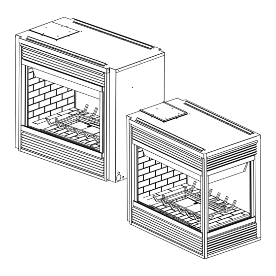
Multisided top/rear vent convertible direct vent fireplaces
Hide thumbs
Also See for 360DVS2:
- Homeowner's installation and operating manual (32 pages) ,
- Installation instructions & homeowner's manual (40 pages) ,
- Installation instructions & homeowner's manual (39 pages)
Table of Contents
Advertisement
INSTALLER/CONSUMER
SAFETY INFORMATION
PLEASE READ THIS MANUAL
BEFORE INSTALLING AND USING
APPLIANCE
WARNING!
IF THE INFORMATION IN THIS
MANUAL IS NOT FOLLOWED
EXACTLY, A FIRE OR EXPLOSION
MAY RESULT CAUSING
PROPERTY DAMAGE, PERSONAL
INJURY OR LOSS OF LIFE.
FOR YOUR SAFETY
Installation and service must be
performed by a qualified installer,
service agency or the gas supplier.
WHAT TO DO IF YOU SMELL GAS:
•
Do not try to light any appliance.
•
Do not touch any electric switch; do
not use any phone in your building.
•
Immediately call your gas supplier
from your neighbor's phone. Follow
the gas suppliers instructions.
•
If you cannot reach your gas
supplier call the fire department.
DO NOT STORE
OR USE GASOLINE OR OTHER
FLAMMABLE VAPORS AND
LIQUIDS IN THE VICINITY OF THIS
OR ANY OTHER APPLIANCE.
Multisided Top/Rear Vent Convertible
Direct Vent Fireplaces
Homeowner's Installation
INSTALLER: Leave this manual with the appliance.
CONSUMER: Retain this manual for future reference.
and Operating Manual
Models:
360DVS2
360DVS3
360DVSL
360DVSR
10006326 1/13 Rev. 8
Advertisement
Table of Contents

Related Manuals for Majestic 360DVS2


Summary of Contents for Majestic 360DVS2
- Page 1 Multisided Top/Rear Vent Convertible Direct Vent Fireplaces Models: 360DVS2 INSTALLER/CONSUMER 360DVS3 SAFETY INFORMATION 360DVSL PLEASE READ THIS MANUAL BEFORE INSTALLING AND USING 360DVSR APPLIANCE WARNING! IF THE INFORMATION IN THIS MANUAL IS NOT FOLLOWED EXACTLY, A FIRE OR EXPLOSION MAY RESULT CAUSING PROPERTY DAMAGE, PERSONAL INJURY OR LOSS OF LIFE.
-
Page 2: Table Of Contents
360 DVS Series Direct Vent Fireplaces Table of Contents Thank you, and Congratulations on your purchase of a Vermont Castings Group fireplace. PLEASE READ THE INSTALLATION & OPERATING INSTRUCTIONS BEFORE USING APPLIANCE. IMPORTANT: Read all instructions and warnings carefully before starting installation. Failure to follow these instructions fully may result in a possible fire hazard and will void the warranty. -
Page 3: Installation And Operating Instructions
360DVS2/ 360DVS3/ 360DVSL/ 360DVSR 3. CAUTION: Due to high glass surface temperature, chil- CERTIFIED TO dren should be carefully supervised when in the same room as fireplace. - Page 4 360 DVS Series Direct Vent Fireplaces Requirements for the Commonwealth of Inspection Massachusetts The state or local gas inspector of the side wall horizontally vented gas fueled equipment shall not All gas fitting and installation of this heater shall only be approve the installation unless, upon inspection, the done by a licensed gas fitter or licensed plumber.
-
Page 5: Fireplace Dimensions
360DVS Series Direct Vent Fireplaces Fireplace Dimensions - 360DVS2 Rear Vent Configuration Electrical Electrical Access Access Gas Line Gas Line Access Access 6326 Top Vent Configuration 360DVS2 rear vent specs Electrical Electrical Access Access Gas Line Gas Line Access Access Fig. -
Page 6: Appliance Dimensions
360 DVS Series Direct Vent Fireplaces Fireplace Dimensions - 360DVS3 / 306DVSL / 360DVSR Rear Vent Configuration Electrical Access Gas Line Access 6326 Top Vent Configuration 360DVS3 rear vent specs Electrical Access Gas Line Access Fig. 1b Fireplace specifications—360DVS3/ 360DDVSL/ 360DVSR 6326 360DVS3 top vent... -
Page 7: Framing Dimensions
Configuration CFM121 Top Vent CFM121 Configuration 360DVS2 REAR VENT CONFIGURATION 8/10/00 CFM122 Fig. 2a Fireplace framing dimensions—360DVS2 CFM122 360DVS2 - TOP VENT CONFIGURATION Framing Dimensions 8/10/00 Ref. Rear Vent Configuration Top Vent Configuration 24” (610 mm) minus two times finishing material thickness to be even with face of unit. - Page 8 360 DVS Series Direct Vent Fireplaces Framing Dimensions - 360DVS3 / 360DVSL / 360DVSR Rear Vent Confiration 360DVSR 360DVSL 360DVS/3/L/R 360DVS3 CFM123 Top Vent Configuration CFM123_360DVS3_dims_RV2 REAR VENT CONFIGURATION 8/10/00 rev. 8-23-02 360DVSR 360DVSL 360DVS/3/L/R 360DVS3 CFM124 Fig. 2b Fireplace framing dimensions—360DVS3/ 360DVSL/ 360DVSR CFM124_360DVS3_TV2 TOP VENT CONFIGURATION 8/10/00...
-
Page 9: Locating Your Fireplace
360DVS Series Direct Vent Fireplaces Locating Your Fireplace Fireplace Louvre Assembly LU584-2 LU584-2 Fig. 3 Locating your gas fireplace Top of Combustion 360DVS Chamber A Wall Location (Fig. 3) locate fireplace Y (Minimum distance between a glass panel and a Bottom of Door Trim CFM146 parallel wall) = 3’... -
Page 10: Hearth
360 DVS Series Direct Vent Fireplaces Hearth Gas Specifications A hearth is not mandatory; however, for aesthetic Max. Min. purposes, we recommend installing a noncombustible Input Input Model Fuel Gas Control BTU/h BTU/h hearth that projects out 12” (305mm) or more from the 360DVS2RN Millivolt 38,000... -
Page 11: Gas Line Installation
360DVS Series Direct Vent Fireplaces 7. Refit the socket assembly back into the electrical 1/2” Gas Supply box and replace the cover plate. 1/2” NPT X 1/2” Flare Shut-Off Valve 8. The EB-1 electrical junction box is now ready to sup- 3/8”... -
Page 12: Optional Top Vent Application
360 DVS Series Direct Vent Fireplaces Remove These Screws Remove These Screws FP1430 Fig. 8 Alternate switch location. Optional Top Vent Application Outer Collar Adapter This appliance is shipped as a rear vent unit. If the FP1431 installation layout requires the unit to be a top vent con- Fig. -
Page 13: Electronic Gas Control Valve
360DVS Series Direct Vent Fireplaces Electronic Gas Control Valve This appliance may be fitted with a Honeywell ignition module. Installation of the remote ON/OFF starter switch on electronic ignition units (Fig. 12): 1. Thread the wiring through the holes on the side PILOT panels of the appliance. -
Page 14: General Venting Information-Termination Location
360 DVS Series Direct Vent Fireplaces General Venting Information - Termination Location INSIDE CORNER DETAIL Fixed Operable Closed CFM145a AREA WHERE TERMINAL IS NOT PERMITTED VENT TERMINATION AIR SUPPLY INLET Canadian Installations US Installations A = Clearance above grade, veranda, porch, 12”... -
Page 15: Termination Clearances
360DVS Series Direct Vent Fireplaces Termination Clearances Termination clearances for buildings with combustible and noncombustible exteriors. Inside Corner Alcove Applications* Outside Corner Combustible 6" (152 mm) Combustible 6" (152 mm) Noncombustible 2" (51 mm) Noncombustible 2" (51 mm) Balcony - Balcony - with no side wall with perpendicular side wall... -
Page 16: How To Use The Vent Graph
360 DVS Series Direct Vent Fireplaces How to Use the Vent Graph Rear Wall Application The vent chart should be read in conjunction with the When installed as a rear vent unit this appliance may be following vent installation instructions to determine the vented directly to a termination located on the rear wall relationship of the vertical and horizontal dimensions of behind the appliance. -
Page 17: Vertical Side Wall Application & Installation
360DVS Series Direct Vent Fireplaces STEP 5 Vent Opening for Combustible Wall Guide vent through the vent hole as you place the appli- 9³⁄₈” (240mm) ance in its installed position. Guide the 4” (102 mm) and 7” (178 mm) collars of the vent termina- tion into the outer ends of the venting. - Page 18 360 DVS Series Direct Vent Fireplaces • The maximum number of 45° elbows permitted per Horizontal plane means no vertical rise exists on this installation is six (6). These elbows can be installed portion of the vent assembly. in either the vertical or horizontal run. •...
- Page 19 360DVS Series Direct Vent Fireplaces STEP 4 Vent Opening for Combustible Wall Apply a bead of silicone to the inner and outer flue 9³⁄₈” (240mm) collars of the fireplace and using appropriate length of pipe section(s) attach to fireplace with three (3) screws. Follow with the installation of the inner and outer elbow, again secure joints as described in “Connecting Vent 9³⁄₈”...
-
Page 20: Below Grade Installation
360 DVS Series Direct Vent Fireplaces 2” (51 mm). Secure termination to the wall with screws Zero Clearance provided, and caulk around the wall plate to weather- Sleeve (if required) proof. 7TDVSNORK (Snorkel) Firestop One alternative to screwing the termination directly to Screws Min. -
Page 21: Vertical Through-The-Roof Application & Installation
360DVS Series Direct Vent Fireplaces Vertical Through-the-Roof Application This Gas Fireplace has been approved for: 1 + 2 + 3 + 4 = 270° • Vertical installations up to 40’ (12 m) in height. Up to a 10’ (3 m) horizontal vent run can be installed within the vent system using a maximum of two 90°... - Page 22 360 DVS Series Direct Vent Fireplaces If there is a room above ceiling level, a Vertical Through-the-Roof Installation firestop spacer must be installed on both 1. Locate your fireplace. the bottom and the top sides of the ceiling joists. (Fig. 35) If an attic is above ceiling 2.
-
Page 23: Twist Lock Venting Components
360DVS Series Direct Vent Fireplaces Twist Lock Venting Components 7TDVRVT Through-the-Wall Rear Vent Termination Starter Kit Model 7TDVSK - Sidewall 584A Starter Kit Model 7TDVSKV - Vertical Venting venting components rear vent term for 7TDVSKV-A: order 1/12 to 6/12 roof pitch 4/6/99 djt for 7TDVSKV-B: order 7/12 to 12/12 roof pitch for 7TDVSKV-F: order flat roof... -
Page 24: Operating Instructions
4. Tilt lower edge of frame out slightly and lift window • Replacement glass (complete with gasket) is frame assembly up and away from the fireplace. available through your Majestic dealer and 5. To reinstall the window frame assembly reverse should only be installed by a licensed qualified the process. -
Page 25: Glass Cleaning
3. Place both side panels along the side of the base. 6. Place the log rear left (B123). The bottom back of NOTE: 360DVS2 is the only 360DV unit that is fitted the log rests on the grate. The notch at the back of... -
Page 26: Lava Rock & Ember Material Placement
360 DVS Series Direct Vent Fireplaces Side of Fireplace B122 B120 B125 B126 B124 B123 B121 LG320 Fig. 40 360DVS log placement. Side of Fireplace B121 B123 B120 LG320 360DVS logs B122 B125 B126 LG321 Fig. 41 360DVS log placement. Lava Rock and Ember Material Placement Flame &... -
Page 27: Flame Characteristics
360DVS Series Direct Vent Fireplaces Turn Turn clockwise counterclockwise 3/8” - 1/2” to decrease to increase (10 - 13mm) flame height flame height Fig. 43 Flame adjustment knob for SIT valve. F584-703 Flame Characteristics Fig. 45 Correct pilot flame appearance. FP390 It is important to periodically perform a visual check FLAME ADJUSTMENT KNOB... -
Page 28: Lighting & Operating Instructions
360 DVS Series Direct Vent Fireplaces Lighting and Operating Instructions FOR YOUR SAFETY, READ BEFORE LIGHTING. WARNING: If you do not follow these instructions exactly, a fire or explosion may result, causing property damage, personal injury or loss of life. A. -
Page 29: Lighting & Operating Instructions (En/Ep)
360DVS Series Direct Vent Fireplaces Lighting and Operating Instructions For Fireplaces equipped with SIT822 Gas Valve (EN or EP) Warning: If you do not follow these instructions exactly, a fire or explosion may result causing property damage, personal injury and loss of life. For your safety, read the following warnings before lighting the appliance: A. -
Page 30: Troubleshooting The Gas Control System
360 DVS Series Direct Vent Fireplaces Troubleshooting the Gas Control System SIT NOVA 820 MILLIVOLT VALVE NOTE: Before troubleshooting the gas control system, be sure external gas shut off is in the “On” position. WARNING: REMOVE GLASS FRONT BEFORE DOING ANY GAS CONTROL SERVICE WORK. SYMPTOM POSSIBLE CAUSES CORRECTIVE ACTION... - Page 31 360DVS Series Direct Vent Fireplaces Troubleshooting the Gas Control System SIT 822 Valve with a Honeywell Electronic Igniter NOTE: Remove glass before servicing. START TURN GAS SUPPLY OFF. CHECK: LINE VOLTAGE (120VAC). LOW VOLTAGE TRANSFORMER TURN ON/OFF SWITCH (19.5 MINIMUM VAC). TO CALL FOR HEAT.
- Page 32 360 DVS Series Direct Vent Fireplaces Troubleshooting – Honeywell VS8421 START CHECK • Supply Line Hooked Up Gas Supply On • Shutoff Valve Open • Lockout Has Engaged. Wait 60 Seconds And Try Again. • For Spark At Electrode While Pilot Lights With Piezo Depressing Piezo Ignitor...
-
Page 33: Fuel Conversion Instructions
360DVS Series Direct Vent Fireplaces PSE Pilot Fuel Conversion Instructions Using a suitable wrench on hexagonal body, un- To convert this appliance from gas type to another, fol- screw the pilot hood assembly from the pilot. Do not low these instructions. Before proceeding, turn control twist the hood itself. - Page 34 360 DVS Series Direct Vent Fireplaces Regulator Cap Conversion Screw Pressure Regu- lator Housing HV120 Fig. 50 Honeywell conversion screw replacement. FC108 Fig. 49 Replace regulator. 10. Reassemble fireplace in the reverse order, except FC108 Honeywell Gas Control Valve (Fig. 50) for the window frame assembly.
-
Page 35: Maintenance
360DVS Series Direct Vent Fireplaces Maintenance Burner and Burner Compartment To obtain proper operation, it is imperative that the pilot and burner’s flame characteristics are steady, not lifting It is important to keep the burner and the burner com- or floating. partment clean. -
Page 36: Replacement Parts
360 DVS Series Direct Vent Fireplaces 3a/b 5a/b 16a/b 4a/b 15a/b 31a/b 34a/b Vermont Castings Group reserves the right to make changes in design, materials, specifications, prices and discontinue colors and products at any 6326 time, without notice. 360DVS 360DVS Series parts 10006326... - Page 37 360DVS Series Direct Vent Fireplaces 360DVS Series (Items marked ‘*’ are not shown in the parts illustration) Ref. Description 360DVS2 360DVS3 360DVSL 360DVSR Log Set (complete) 10006350 10006350 10006350 10006350 Log - Rear (B120) 10006315 10006315 10006315 10006315 Log - Front Left (B121)
- Page 38 360 DVS Series Direct Vent Fireplaces 360DVS Series (continued) (Items marked ‘*’ are not shown in the parts illustration) Ref. Description 360DVS2 360DVS3 360DVSL 360DVSR Louvre Assembly, side bottom 10000040 10000040 10000040 10000040 Louvre Assembly, end top 10002411 10002411 10002411...
-
Page 39: Optional Accessories
360DVS Series Direct Vent Fireplaces Optional Accessories FK12 Fan Kits This auxiliary fan system increases the efficiency of the FK24 Fan Assembly circulation of the heating air. This auxiliary fan system increases the efficiency of the The FK12 Fan Assembly is a fixed speed fan system circulation of the heated air. -
Page 40: Remote Controls
The DV360TKMP Medium Trim Kit in polished brass is cally connected and grounded in accordance available for the 360DVS2 model only. with local codes, or in the absence of local Each kit contains 4 polished brass trim pieces and the codes, with the current CSA C22.1 Canadian... - Page 41 360DVS Series Direct Vent Fireplaces 10006326...
- Page 42 360 DVS Series Direct Vent Fireplaces 10006326...
-
Page 43: Warranty
360DVS Series Direct Vent Fireplaces LIMITED LIFETIME WARRANTY Lifetime Warranty The following components are warranted for life to the original owner, subject to proof of purchase: Firebox, Combus- tion Chamber, Heat Exchanger, Grate and Stainless Steel Burners. Five Year Warranty The following components are warranted for five (5) years to the original owner, subject to proof of purchase: Ceramic Fiber Logs. -
Page 44: Energuide
Efficiency Ratings Model EnerGuide Ratings Steady State (%) D.O.E. Fireplace Efficiency (%) Fan-OFF Fan-ON (AFUE%) 360DVS2RN 62.4 360DVS2RP 62.4 360DVS2EN 62.4 360DVS2EP 62.4 360DVS3RN 62.4 360DVS3RP 62.4 360DVS3EN 62.4 360DVS3EP 62.4 360DVSLRN 62.4 306DVSLRP 62.4 360DVSLEN 62.4 360DVSLEP 62.4 360DVSRRN 62.4 360DVSRRP 62.4...
Need help?
Do you have a question about the 360DVS2 and is the answer not in the manual?
Questions and answers