Table of Contents
Advertisement
Full-Feature Vehicle Security System for
Factory-Equipped Remote Keyless Entry
07/03 MI/AL-100-H
Full-Feature Vehicle Security System for
Factory-Equipped Remote Keyless Entry
07/03 MI/AL-100-H
AL-100-H
Transmitters
INSTALLATION
INSTRUCTIONS
COPYRIGHT: OMEGA RESEARCH & DEVELOPMENT 2003
AL-100-H
Transmitters
INSTALLATION
INSTRUCTIONS
COPYRIGHT: OMEGA RESEARCH & DEVELOPMENT 2003
Advertisement
Table of Contents

Summary of Contents for Omega AL-100-H
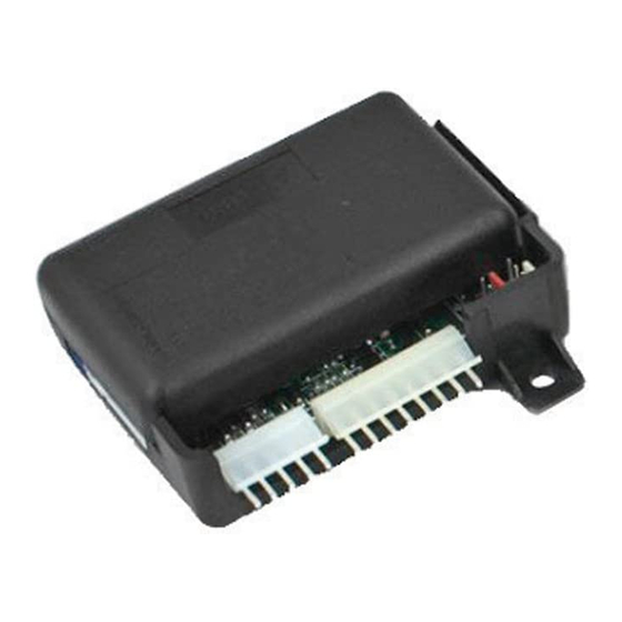
- Page 1 AL-100-H Full-Feature Vehicle Security System for Factory-Equipped Remote Keyless Entry Transmitters INSTALLATION INSTRUCTIONS COPYRIGHT: OMEGA RESEARCH & DEVELOPMENT 2003 07/03 MI/AL-100-H AL-100-H Full-Feature Vehicle Security System for Factory-Equipped Remote Keyless Entry Transmitters INSTALLATION INSTRUCTIONS COPYRIGHT: OMEGA RESEARCH & DEVELOPMENT 2003...
- Page 2 6-Pin Arm/Disarm Wiring Harness Determining Connection Type ...................... 6 Switch #5- Current Sensing: With this feature turned on, when the AL-100-H is Armed it can Connection Type Wiring Diagrams ..................7-11 then be Activated by its sensing a current draw from the vehicle's battery. To have the 5-Pin Main Wiring Harness system Activate if a current draw is sensed, set switch #5 “down”;...
- Page 3 Ensure that moisture, vibration and tempera- Switch #3- Last Door Arming: With this feature turned on the AL-100-H will arm itself ture extremes are minimized. Acceptable locations include mounting behind the dash, be- automatically every time one of the vehicle's doors is closed.
- Page 4 Mercedes vehicles. In most all of these cases, Omega will have an optional specialized power doorlock interface available, in which case any needed instructions will be included with the specialized interface.
- Page 5 - any change in the electrical state of these wires while the Pink and Gray wires receive a 5 Wire Reversal Doorlocks using the Positive pulse will cause the AL-100-H not to arm or disarm. The White and Brown wires have optional DLS socket and 2 SPDT relays...
- Page 6 White and Brown wires. Because of this polarity-learning circuitry, these two wires must be CONNECTION: DLP-N3 harness Red connected when the AL-100-H is first supplied Power and Ground. Also, if the White or Brown Connect directly as connector plugs into wire is not needed, the unused wire(s) should be grounded.
- Page 7 Unlock wires are cut. The doorlock relays and RKE unit are also separate. Ground system. 3 Wire Negative Doorlocks using the AL-100-H Control Unit The Type 2 Connection: When the Gray or Pink wires receive a Positive pulse the outputs security system will arm or disarm.
- Page 8 12 Volt Positive output for optional relay coils only; optional relays are needed to connect Unit Positive or the AL-100-H to the reversal type of power doorlocks. Negative Lock All connections should be with proper terminals, connectors, or by soldering and insulating Type 2 Connection: Shows with quality vinyl electrical tape or heat shrink tubing.
- Page 9 Control Brown wire to Module Unlock wire- Why does the AL-100-H have power doorlock outputs? Keep in mind that the existing Switch or Motor factory remote keyless entry system and existing power doorlocks are operating the AL-100- White wire H’s arming and disarming. With these outputs, the AL-100-H is simply providing these...
- Page 10 The Type 4 Connection: This system is used to interface the AL-100-H with many Ford, Negative chassis ground. If the horn sounds when probed in this manner, a direct Lincoln and Mercury vehicles. In this type of Remote Keyless Entry system, all of the doorlock connection may be made.
- Page 11 Type 5 Connection: This connection configuration is a universal type that will interface confirmation chirps, and when AL-100-H is activated. Unlike the Brown wire, this output with any vehicle that remotely unlocks the driver's door first. With this system all of the relays pulses .5 second on, .5 second off when a system activation does occur.
- Page 12 1 2 3 4 5 1 2 3 4 5 6 or security system The Red wire's function is to supply Constant Positive 12 Volts for the AL-100-H’s system Recommended connection points for the White wire control unit. operation. When 12 Volts is first applied to the Red wire, the system will be activated. The...
- Page 13 Orange wire connecting the socket to the control module is a Negative starter interrupt Electronic Light and/or additional circuits to output, which is active whenever the AL-100-H is in an armed state. Sensor Switch Switch this wire, diode-isolation may...
- Page 14 +12 Volt. 5-Pin Connector Dash-mounted Red and White wire To Ground Switch Switch Ignition Starter Disable Red AL-100-H Note: The Driver connections, and the Pin Switch will often Relay Switch wire to the Ignition Control diagram on the...
- Page 15 The Yellow wire is an ignition "on" input to the AL-100-H. Typical Negative Switching Domelight System switches; the correct CONNECTION: This wire supplies Positive 12 Volts to the control module whenever the 1 2 3 4 5 6 7 8 9 0 1 2...
- Page 16 1 2 3 4 5 6 7 8 9 0 1 2 3 4 5 6 7 8 9 0 Switch AL-100-H Wiring Diagram 1 2 3 4 5 6 7 8 9 0 1 2 3 4 5 6 7 8 9 0...


Need help?
Do you have a question about the AL-100-H and is the answer not in the manual?
Questions and answers