Table of Contents
Advertisement
Advertisement
Table of Contents

Related Manuals for Asus P2-99B


Summary of Contents for Asus P2-99B
- Page 1 P2-99B ® Pentium III / II / Celeron Motherboard USER’S MANUAL...
- Page 2 Product warranty or service will not be extended if: (1) the product is repaired, modified or altered, unless such repair, modification of alteration is authorized in writing by ASUS; or (2) the serial number of the product is defaced or missing.
- Page 3 WWW: www.asus.com FTP: ftp.asus.com.tw/pub/ASUS ASUS COMPUTER GmbH (Europe) Marketing Address: Harkort Str. 25, 40880 Ratingen, BRD, Germany Telephone: 49-2102-445011 Fax: 49-2102-442066 Email: sales@asuscom.de Technical Support Hotline: 49-2102-499712 BBS: 49-2102-448690 Email: tsd@asuscom.de WWW: www.asuscom.de FTP: ftp.asuscom.de/pub/ASUSCOM ASUS P2-99B User’s Manual...
-
Page 4: Table Of Contents
How This Manual Is Organized ............7 Item Checklist ..................7 II. FEATURES ..................8 Features of the ASUS P2-99B Motherboard ........8 The ASUS P2-99B Motherboard ..........11 III. HARDWARE SETUP ..............12 Layout of the ASUS P2-99B Motherboard ........12 Hardware Setup Steps ............... - Page 5 ASUS Contact Information ........... 64 Uninstalling Programs ..............65 VI. SOFTWARE REFERENCE ............67 ASUS PC Probe (only w/ optional hardware monitor)..... 67 Intel LANDesk Client Manager (only w/ optional hardware monitor) .......... 72 Desktop Management Interface (DMI) ..........78 VII.
-
Page 6: Federal Communications Commission Statement
Canadian Department of Communications Statement This digital apparatus does not exceed the Class B limits for radio noise emissions from digital apparatus set out in the Radio Interference Regulations of the Cana- dian Department of Communications. ASUS P2-99B User’s Manual... -
Page 7: Introduction
(1) Support CD with drivers and utilities (1) This Motherboard User’s Manual ASUS IrDA-compliant infrared module (optional) ASUS USB/MIR module (optional) ASUS CIDB chassis sensor module (optional) ASUS S370 CPU card (optional) ASUS PCI-L101 Wake-On-LAN 10/100 Ethernet Card (optional) ASUS P2-99B User’s Manual... -
Page 8: Features
II. FEATURES Features of the ASUS P2-99B Motherboard The ASUS P2-99B is carefully designed for the demanding PC user who wants advanced features processed by the fastest CPU. Specifications: ® ® • Multi-Speed: Supports Intel Pentium III (450MHz and faster), Pentium (233MHz to 450MHz), and Celeron (266MHz and faster) processors. - Page 9 • PC’98 Compliant: Both the BIOS and hardware levels of ASUS smart series of motherboards meet PC’98 compliancy. The new PC’98 requirements for sys- tems and components are based on the following high-level goals: Support for...
- Page 10 Voltage specifications are more critical for future processors, so monitoring is necessary to ensure proper system configuration and management. • Chassis Intrusion Detection (only w/optional hardware monitor): Supports chassis-intrusion monitoring through the optional ASUS CIDB module and Intel LDCM. ASUS P2-99B User’s Manual...
-
Page 11: The Asus P2-99B Motherboard
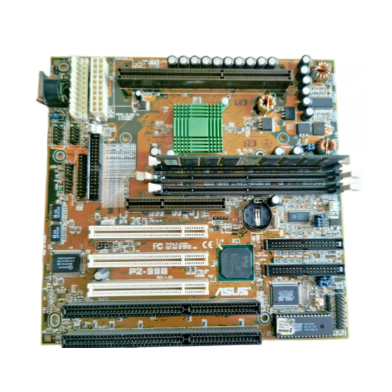
II. FEATURES The ASUS P2-99B Motherboard Intel 440ZX AT Power ATX Power AGPset Slot 1 3 DIMM Sockets Connectors Keyboard Serial Ports COM1 & COM2 USB/MIR Parallel Port Floppy Connector AGP Port 3 PCI Slots Multi-I/O Hardware Monitor (optional) Programmable... -
Page 12: Hardware Setup
III. HARDWARE SETUP Layout of the ASUS P2-99B Motherboard PS/2 CPU_FAN KB-PS2KB Slot 1 Keyboard KBPWR Intel PWR_FAN COM 1 COM 2 440ZX AGPset Serial Ports VCORE DIMM Socket 1 (64/72-bit, 168-pin module) FLOPPY DIMM Socket 2 (64/72-bit, 168-pin module) - Page 13 36 ATX Power Supply Connector (20 pins) 23) PS/2 p. 36 AT Power Supply Connector (20 pins) The optional onboard hardware monitor uses the address 290H-297H so legacy ISA cards must not use this address otherwise conflicts will occur. ASUS P2-99B User’s Manual...
-
Page 14: Hardware Setup Steps
ATX power supply. Your computer will not function if you set this to Enable and if you do not have the appropriate ATX power supply. KBPWR 1 2 3 1 2 3 Disable Enable (Default) P2-99B P2-99B Keyboard Power Up ASUS P2-99B User’s Manual... - Page 15 Normal Test (Default) P2-99B P2-99B CPU Core Voltage Selection WARNING! Using a higher voltage Test for VCORE or 3.66Volts for VIO may help when overclocking but may result in the shortening of your computer component’s life. It is strongly recommended that you leave these jumpers on their default settings.
- Page 16 4.0x(4/1) 6.5x(13/2) 4.5x(9/2) 5.0x(5/1) 5.5x(11/2) 6.0x(6/1) P2-99B 7.0x(7/1) 7.5x(15/2) 8.0x(8/1) P2-99B CPU Core-to-Bus Frequency Multiple Settings WARNING! Frequencies above 100MHz exceed the specifications for the on- board Intel Chipset and are not guaranteed to be stable. ASUS P2-99B User’s Manual...
- Page 17 Overclocking your processor is not recommended. It may result in a slower speed. Voltage Regulator Output Selection (VID) is not required for Pentium III / II/ Celeron processors because they send VID signals directly to the onboard power controller. ASUS P2-99B User’s Manual...
-
Page 18: Spd Support
If your DIMMs are not PC100-compliant, set the CPU external frequency to 66MHz for system stability. • ASUS motherboards support SPD (Serial Presence Detect) DIMMs. This is the memory of choice for best performance vs. stability. •... - Page 19 Lock 20 Pins 60 Pins 88 Pins P2-99B P2-99B 168-Pin DIMM Memory Sockets The DIMMs must be 3.3Volt unbuffered SDRAMs. To determine the DIMM type, check the notches on the DIMMs (see figure below). 168-Pin DIMM Notch Key Definitions (3.3V)
- Page 20 III. HARDWARE SETUP (This page was intentionally left blank.) ASUS P2-99B User’s Manual...
-
Page 21: Central Processing Unit (Cpu)
SECC/SECC2, or a Celeron™ processor packaged in a Single Edge Proces- sor Package (SEPP). An ASUS S370 CPU card can allow Socket 370 processors to be used on any ASUS motherboard with the Slot 1 connector (See ASUS S370 CPU Card in APPENDIX for instructions on using this card). -
Page 22: Installing The Processor
Four Pins and metal clip NOTE: The SEPP heatsink and fan (for Intel Celeron processors) is similar to the SECC2 heatsink and fan except that the clamping design is different. ASUS P2-99B User’s Manual... - Page 23 II only: The SECC locks should be outward when se- cured so that the lock shows through the retention mechanism’s lock holes. SECC SECC2/SEPP Lock hole Lock hole CPU fan CPU fan cable to cable to fan fan connector connector ASUS P2-99B User’s Manual...
-
Page 24: Asus Smart Thermal Solutions (Only For Motherboards With Hardware Monitor)
III. HARDWARE SETUP ASUS Smart Thermal Solutions (only for motherboards with hardware monitor) ASUS provides two smart solutions to Slot 1 CPU thermal problems: the ASUS Smart Fan or ASUS S-P2FAN and the ASUS P2T-Cable. Thermal Cable CPU Fan Cable... -
Page 25: Recommended Heatsinks For Slot 1 Processors
The recommended heatsinks for the Slot 1 processors are those with three-pin fans, such as the ASUS Smart Fan, that can be connected to the motherboard’s CPU fan connector. These heatsinks dissipate heat more efficiently and with an optional hard- ware monitor, they can monitor the fan’s RPM and use the alert function with the... -
Page 26: Expansion Cards
(to gain access, double-click the System icon under the Con- trol Panel program). Ensure that no two devices share the same IRQs or your com- puter will experience problems when those two devices are in use at the same time. ASUS P2-99B User’s Manual... -
Page 27: Assigning Dma Channels For Isa Cards
Accelerated Graphics Port (AGP) This motherboard provides an accelerated graphics port (AGP) slot to support a new generation of graphics cards with ultra-high memory bandwidth, such as an ASUS 3D hardware accelerator. P2-99B P2-99B Accelerated Graphics Port (AGP) ASUS P2-99B User’s Manual... -
Page 28: External Connectors
(Pin 5 is removed to prevent inserting in the wrong orienta- tion when using ribbon cables with pin 5 plugged). Floppy Disk Drive Connector P2-99B Pin 1 P2-99B Floppy Disk Drive Connector ASUS P2-99B User’s Manual... - Page 29 IRQ through “Onboard Serial Port” in Chipset Features of BIOS SETUP. (Pin 10 is removed to prevent inserting in the wrong orientation when using ribbon cables with pin 10 plugged). COM 1 COM 2 Pin 1 Pin 1 P2-99B P2-99B Serial Port Headers ASUS P2-99B User’s Manual...
- Page 30 Primary or Secondary IDE connectors will cause the LED to light up. TIP: If the case-mounted LED does not light, try reversing the 2-pin plug. P2-99B IDELED P2-99B IDE Activity LED ASUS P2-99B User’s Manual...
- Page 31 8. Wake-On-LAN Connector (3-pin WOL_CON) This connector connects to a LAN card with a Wake-On-LAN output, such as the ASUS PCI-L101. The LAN card powers up the system when a wakeup packet or signal is received from the network. IMPORTANT: This feature requires that the WAKE On LAN Power Up Con-...
- Page 32 15. System Warning Speaker Connector (4-pin SPEAKER) This 4-pin connector connects to the case-mounted speaker. Reset Switch System Speaker Power Switch Keyboard Lock SMI Switch P2-99B Message LED Power LED Requires an ATX power supply. P2-99B System Panel Connections ASUS P2-99B User’s Manual...
- Page 33 2: USB Port 0 - 11: USB Port 1 - 1: USB +5 Volt 10: USB +5 Volt P2-99B PS/2 Mouse, USB, IrDA Module Connector Optional USB/MIR 17. IrDA-Compliant Infrared Module Connector (5-pin IR) This connector supports the optional wireless transmitting and receiving infrared module.
- Page 34 “chassis signal” lead. This occurs when a panel switch or light detector is triggered. This function requires the optional ASUS CIDB Chassis Intrusion Photo Sensor Module (see APPENDIX) to be installed.
- Page 35 I C bus, which is a multi-master bus, that is, multiple chips can be connected to the same bus and each one can act as a master by initiating data transfer. P2-99B P2-99B SMBus Connector ASUS P2-99B User’s Manual...
- Page 36 P2-99B +12.0 Volts +5.0 Volts P2-99B ATX Power Connector 23. AT Power Supply Connector (12-pin PS/2) This connector connects to a standard 5 Volt power supply. To connect the leads from the power supply, ensure first that the power supply is not plugged. Most power supplies provide two plugs (P8 and P9), each containing six wires, two of which are black.
-
Page 37: Power Connection Procedures
Shut down the computer?. The power supply should turn off after Windows shuts down. NOTE: The message “You can now safely turn off your computer” will not appear when shutting down with ATX power supplies. ASUS P2-99B User’s Manual... -
Page 38: Bios Setup
To save your current BIOS, type [1] at the Main Menu and then press <Enter>. The Save Current BIOS To File screen appears. Type a filename and the path, for example, A:\XXX-XX.XXX and then press <Enter>. ASUS P2-99B User’s Manual... - Page 39 BIOS update, press Y to start the update. The utility starts to program the new BIOS information into the flash ROM. When the pro- gramming is finished, Flashed Successfully will be displayed. Follow the onscreen instruc- tions to continue. ASUS P2-99B User’s Manual...
-
Page 40: Managing And Updating Your Motherboard's Bios
Updating BIOS Procedures (only when necessary) 1. Download an updated ASUS BIOS file from the Internet (WWW or FTP) or a BBS (Bulletin Board Service) (see ASUS CONTACT INFORMATION on page 3 for details) and save to the disk you created earlier. -
Page 41: Bios Setup
Reset button on the system case. You can also restart by turning the system off and then back on again. But do so only if the first two methods fail. When you invoke Setup, the CMOS SETUP UTILITY main program screen will appear with the following options: ASUS P2-99B User’s Manual... -
Page 42: Load Defaults
To set the date, highlight the “Date” field and then press either <Page Up>/<Page Down> or <+>/<–> to set the current date. Follow the month, day and year format. Valid values for month, day and year are: Month: (1 to 12), Day: (1 to 31), Year: (up to 2079). ASUS P2-99B User’s Manual... - Page 43 IDE hard disks; set it to Large for drives over 528MB that do not support LBA. Large type of drive can only be used with MS-DOS and is very uncommon. Most IDE drives over 528MB support the LBA mode. ASUS P2-99B User’s Manual...
-
Page 44: Asus P2-99B User's Manual
If you are using a VGA or any higher resolution card, choose EGA/VGA. Halt On This field determines which types of errors will cause the system to halt. Choose from All Errors; No Errors; All,But Keyboard, All,But Diskette; and All,But Disk/Key. ASUS P2-99B User’s Manual... -
Page 45: Bios Features Setup
Be- cause of conflicts with new operating systems, for example, during installation of new software, you may have to set this to Disabled to prevent write errors. ASUS P2-99B User’s Manual... - Page 46 This allows the enabling or disabling of the S.M.A.R.T. (Self-Monitoring, Analysis and Reporting Technology) system which utilizes internal hard disk drive monitor- ing technology. This feature is normally disabled because system resources used in this feature may decrease system performance. ASUS P2-99B User’s Manual...
- Page 47 The default setting is System, where the system prompts for the User Password every time you start your system. The other option is Setup, where the system goes through its startup routine unless the Setup utility is called, when the system prompts for the Supervisor Password. ASUS P2-99B User’s Manual...
-
Page 48: Chipset Features Setup
SDRAM MA Wait State (Normal) This controls the leadoff clocks for CPU read cycles. Leave on default setting. Snoop Ahead (Enabled) Enabled will allow PCI streaming. Leave on default setting. Host Bus Fast Data Ready (Disabled) Leave on default setting. ASUS P2-99B User’s Manual... - Page 49 Onboard Serial Port 1 (3F8H/IRQ4) Settings are 3F8H/IRQ4, 2F8H/IRQ3, 3E8H/IRQ4, 2E8H/IRQ10, and Disabled for the onboard serial connector. Onboard Serial Port 2 (2F8H/IRQ3) Settings are 3F8H/IRQ4, 2F8H/IRQ3, 3E8H/IRQ4, 2E8H/IRQ10, and Disabled for the onboard serial connector. ASUS P2-99B User’s Manual...
- Page 50 Because each IDE device may have a different Mode timing (0, 1, 2, 3, 4), it is necessary for these to be independent. The default setting of Auto will allow autodetection to ensure optimal performance. ASUS P2-99B User’s Manual...
-
Page 51: Power Management Setup
“Power” will appear in the “Control Panel.” Choose “Advanced” in the Power Management Field. Video Off Option (Suspend -> Off ) This field determines when to activate the video off feature for monitor power management. The settings are Always On and Suspend -> Off. ASUS P2-99B User’s Manual... - Page 52 4 seconds. Suspend allows the button to have a dual function where pressing less than 4 seconds will place the system in sleep mode. Regardless of the setting, holding the ATX switch for more than 4 seconds will power off the system. ASUS P2-99B User’s Manual...
- Page 53 NOTE: If any of the monitored items are out of range, an error message will appear: “Hardware Monitor found an error, enter POWER MANAGEMENT SETUP for details”. You will then be prompted to “Press F1 to continue, DEL to enter SETUP”. ASUS P2-99B User’s Manual...
-
Page 54: Pnp And Pci Setup
ICU, you must set the field for that IRQ to Yes. For example: If you install a legacy ISA card that requires IRQ 10, then set IRQ10 Used By ISA to Yes............................ASUS P2-99B User’s Manual... - Page 55 USB devices, you may set this feature to Disabled to save an extra IRQ# for expansion cards. VGA BIOS Sequence (PCI/AGP) You can select the search order for your VGA card(s). PCI/AGP will detect PCI VGA cards before AGP, and AGP/PCI will detect AGP cards before PCI VGA. ASUS P2-99B User’s Manual...
-
Page 56: Load Bios Defaults
<Enter>. The system displays a confirmation message on the screen. Press <Y> and then <Enter> to confirm. Press <N> and then <Enter> to abort. This feature does not affect the fields on the Standard CMOS Setup screen. ASUS P2-99B User’s Manual... -
Page 57: Supervisor Password And User Password
To erase the RTC RAM: (1) Unplug your computer, (2) Short the solder points, (3) Turn ON your computer, (4) Hold down <Delete> during bootup and enter BIOS setup to re-enter user preferences. CLRTC P2-99B P2-99B Clear RTC RAM ASUS P2-99B User’s Manual... -
Page 58: Ide Hdd Auto Detection
The auto-detection feature can only detect one set of parameters for a particular IDE hard drive. Some IDE drives can use more than one set. This is not a problem if the drive is new and empty. ASUS P2-99B User’s Manual... - Page 59 If the auto-detected parameters do not match the ones that should be used for your disk, do not accept them. Press <N> to reject the presented settings and enter the correct ones manually from the Standard CMOS Setup screen. ASUS P2-99B User’s Manual...
-
Page 60: Save & Exit Setup
Select this option to exit the Setup utility without saving the modifications you specify during the current session. To exit without saving, highlight the “Exit Without Sav- ing” option on the main screen and then press <Enter>. ASUS P2-99B User’s Manual... -
Page 61: Software Setup
Navigation Button Descriptions Motherboard Info displays information on your motherboard, BIOS, and CPU. Browse This CD allows you to see the contents of the ASUS Support CD. User’s Manual displays the motherboard user’s manual in pdf format. Technical Support Form opens up a blank Technical Support Request Form for you to fill and print out when you run into technical difficulties and need technical assistance. -
Page 62: Installation Submenu
NOTE: Will not run with LDCM installed. To uninstall a program, see Uninstalling Programs at the end of this section. ASUS LiveUpdate installs a program to help you update your BIOS or download a BIOS image file. -
Page 63: Dos Utility Submenu
DOS Utility Submenu. DOS Utility Submenu ASUS DMI Configuration Utilty provides information on using the DMI configu- ration utility. This utility is located in the DMI folder under the root directory of the support CD Flash BIOS Utility (DOS Version) provides information on the Flash BIOS utility (AFLASH.EXE). -
Page 64: Asus Contact Information
V. SOFTWARE SETUP Click here to bring up ASUS Contact Information. ASUS Contact Information ASUS P2-99B User’s Manual... -
Page 65: Uninstalling Programs
1. Double-click here to open the Add/Remove Programs Properties dialog box. 2. Select the program you wish to remove and click here. 3. Click here. ASUS P2-99B User’s Manual... - Page 66 V. SOFTWARE SETUP (This page was intentionally left blank) ASUS P2-99B User’s Manual...
-
Page 67: Software Reference
ASUS Utility, and then click Probe Vx.xx. The PC Probe icon will appear on the taskbar’s system tray indicating that ASUS PC Probe is running. Clicking the icon will allow you to see the status of your PC. ASUS P2-99B User’s Manual... -
Page 68: Using Asus Pc Probe
Fan Monitor Shows the PC’s fan rotation. Fan Warning threshold adjustment (Move the slider up to increase the threshold level or down to decrease the threshold level) Voltage Monitor Shows the PC’s voltages. ASUS P2-99B User’s Manual... - Page 69 Information Hard Drives Shows the used and free space of the PC’s hard disk drives and the file allocation table or file system used. Memory Shows the PC’s memory load, memory usage, and paging file usage. ASUS P2-99B User’s Manual...
- Page 70 Shows information pertinent to the PC, such as CPU type, CPU speed, and in- ternal/external frequencies, and memory size. Utility Lets you run programs outside of the ASUS Probe modules. To run a program, click Execute Program. ASUS P2-99B User’s Manual...
-
Page 71: Asus Pc Probe Task Bar Icon
VI. SOFTWARE REFERENCE ASUS PC Probe Task Bar Icon Right clicking the PC Probe icon will bring up a menu to open or exit ASUS PC Probe and pause or resume all sys- tem monitoring. When the ASUS PC Probe... -
Page 72: Intel Landesk Client Manager (Only W/ Optional Hardware Monitor)
Windows registry. From this point on, when you run Client Manager or open the Select Computer dialog box, Client Manager checks to see if these computers (listed in the registry) are available and healthy. Main Client Manager Window ASUS P2-99B User’s Manual... -
Page 73: Using The Taskbar Icons
Opens the File Transfer dialog box Tools | Transfer Files Tools | Reboot Reboots the computer Tools | DMI Explorer Opens the DMI Explorer Opens the Set Access Rights dialog box Tools | Set Access Rights ASUS P2-99B User’s Manual... -
Page 74: Using The Select Computer Dialog Box
Removes a computer from the list of discovered computers Wakes up a sleeping computer Shows all discovered computers Shows only available computers Shows only unhealthy computers Shows a simple list view Shows a detailed list view ASUS P2-99B User’s Manual... -
Page 75: To Select A Computer
You may need to change your list view to display all computers. 2. Click the Wake Up Computer button on the toolbar to wake up the selected computer(s) or press <Alt>+<W>. ASUS P2-99B User’s Manual... -
Page 76: Displaying The Properties Of A Client Computer
System information is not stored in this same database, that information is not avail- able for a computer with a status of Unavailable. Remember that some items may not be current if the properties have changed while the computer was off the net- work. ASUS P2-99B User’s Manual... -
Page 77: Understanding The Computer Status Icons
Warning, or Critical) is not known. Normal (Mobile) A computer that includes support for mobile PC fea- tures, such as mobile battery. Mobile computers display the same array of health icons (above) used for non- mobile computers. ASUS P2-99B User’s Manual... -
Page 78: Desktop Management Interface (Dmi)
VI. SOFTWARE REFERENCE Desktop Management Interface (DMI) Introducing the ASUS DMI Configuration Utility This motherboard supports DMI within the BIOS level and provides a DMI Con- figuration Utility to maintain the Management Information Format Database (MIFD). DMI is able to auto-detect and record information pertinent to a computer’s system such as the CPU type, CPU speed, and internal/external frequencies, and memory size. -
Page 79: Using The Asus Dmi Configuration Utility
VI. SOFTWARE REFERENCE Using the ASUS DMI Configuration Utility NOTE: The following screen displays are provided as examples only and may not reflect the screen contents on your system. Edit DMI (or delete) Use the (left-right) cursors to move the top menu items and the (up-down) cursor to move between the left hand menu items. - Page 80 You can load the BIOS defaults from a MIFD file and can clear all user modified and added data. You must reboot your computer in order for the defaults to be saved back into the Flash BIOS. ASUS P2-99B User’s Manual...
-
Page 81: Appendix
VII. APPENDIX The ASUS CIDB Chassis Intrusion Sensor Module The optional ASUS CIDB is a module for providing audio alarm and logging when there is an intrusion into the chassis of a computer system. The module detects a chas- sis intrusion by either light striking its photo sensor or by contact when its switch connectors are shorted by chassis-mounted momentary toggle switches. -
Page 82: Setting Up The Asus Cidb
VII. APPENDIX Setting up the ASUS CIDB Enable Disable CR2032 3V JP1: Enable/Disable Lithium Cell the Photo Sensor Buzzer best range +5 volt standby (sensitive) 0 (not sensitive) from power supply CON: Sensitivity adjustment for the photo sensor, (0) is least sensitive... -
Page 83: The Asus S370 Cpu Card
The following picture shows the ASUS S370 CPU card with a plastic retainer at- tached to the edge. The retainer is used to hold the ASUS S370 CPU card in place using the motherboard’s Slot 1 retention mechanism. - Page 84 VII. APPENDIX Setting up the ASUS S370 CPU Voltage Screw Hole Screw Hole Brown Lever ASUS S370 Jumper Settings Setting the CPU voltage is not necessary for current socket 370 processors. If re- quired, your socket 370 processor should have its voltage requirement printed on its surface or documentation.
-
Page 85: Asus Pci-L101 Fast Ethernet Card
Motherboard type Other If you are using the ASUS PCI-L101 on an ASUS motherboard, leave the jumper on its defaut setting of “ASUS.” If you are using another brand of motherboard, set the jumper to “Other.” Connect the Wake on LAN (WOL) output signal to the motherboard’s WOL_CON in order to utilize the wake on LAN feature of the moth-... -
Page 86: Software Driver Support
A: To enable Wake-On-LAN function, your system requires Ethernet LAN adapter card that can activate Wake-On-LAN function, a client with Wake-On-LAN capa- bility, and software such as LDCM Rev. 3.10 or up that can trigger wake-up frame. ASUS P2-99B User’s Manual... -
Page 87: Glossary
PIO (Programmable I/O) IDE requires that the CPU be involved in IDE access and waiting for mechanical events. Bus master IDE transfers data to/from the memory without interrupting the CPU. Bus master IDE driver and bus master IDE hard disk drives are required to support bus master IDE mode. ASUS P2-99B User’s Manual... - Page 88 Data (SIMD), which is built into the new Intel Pentium PP/MT (P55C) and Pentium II (Klamath) CPU as well as other x86-compatible microprocessors. The MMX in- structions are designed to accelerate multimedia and communications applications, such as 3D video, 3D sound, video conference. ASUS P2-99B User’s Manual...
- Page 89 PIO mode, which only uses the rising edge of IDE command signal to transfer data, DMA/33 uses both rising edge and falling edge. Hence, the data transfer rate is double of the PIO mode 4 or DMA mode 2. (16.6MB/s x2 = 33MB/s). ASUS P2-99B User’s Manual...
- Page 90 With USB, the traditional complex cables from back panel of your PC can be eliminated. ASUS P2-99B User’s Manual...
- Page 91 (This page was intentionally left blank.) ASUS P2-99B User’s Manual...
- Page 92 (This page was intentionally left blank.) ASUS P2-99B User’s Manual...
- Page 93 (This page was intentionally left blank.) ASUS P2-99B User’s Manual...
- Page 94 (This page was intentionally left blank.) ASUS P2-99B User’s Manual...
- Page 95 (This page was intentionally left blank.) ASUS P2-99B User’s Manual...
- Page 96 (This page was intentionally left blank.) ASUS P2-99B User’s Manual...
Need help?
Do you have a question about the P2-99B and is the answer not in the manual?
Questions and answers