Briggs & Stratton 700 DOV Series Repair Manual

Briggs & Stratton 700 DOV Series Repair Manual

Air-cooled engines

Advertisement

Repair Manuals for other
Briggs & Stratton Engines:
273521 Twin Cylinder OHV Air-Cooled Engines
276781 Single Cylinder OHV Air-Cooled Engines
271172 Twin Cylinder L-Head Air-Cooled Engines
270962 Single Cylinder L-Head Air-Cooled Engines
276535 Two-Cycle Snow Engines
CE8069 Out of Production Engines (1919-1981)
Quality Starts With A
Master Service Technician
www.thePowerPortal.com (Dealers)
bRiGGsandstRattoN.coM (consumers)
BRIGGS&STRATTON
coRPoRatioN
Part No. 277527-12/09
Post office box 702
Milwaukee, wi 53201 usa
©2009 Briggs & Stratton Corporation
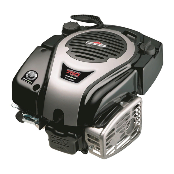
700/750 Series DOV
Air-Cooled Engines

Advertisement

Table of Contents
loading

Summary of Contents for Briggs & Stratton 700 DOV Series

  • Page 1 Repair Manuals for other Briggs & Stratton Engines: 273521 Twin Cylinder OHV Air-Cooled Engines 276781 Single Cylinder OHV Air-Cooled Engines 271172 Twin Cylinder L-Head Air-Cooled Engines 270962 Single Cylinder L-Head Air-Cooled Engines 700/750 Series DOV 276535 Two-Cycle Snow Engines CE8069 Out of Production Engines (1919-1981) Air-Cooled Engines Quality Starts With A Master Service Technician...
  • Page 3 FORWARD This manual was written to assist engine technicians and service personnel with the repair and maintenance procedures for Briggs & Stratton engines. It assumes that persons using this manual have been properly trained in and are familiar with the servicing procedures for these products, including the proper use of required tools and safety equipment and the application of appropriate safety practices.
  • Page 4 This engine repair manual includes the following engine models: • MODEL 090600 • MODEL 100600 • MODEL 100800...
  • Page 5 SECTION 1 - Safety, Maintenance and Adjustments SECTION 2 - Troubleshooting SECTION 3 - Exhaust Systems SECTION 4 - Fuel Systems and Carburetion SECTION 5 - Governor Systems SECTION 6 - Cylinder Heads and Valves SECTION 7 - Starters SECTION 8 - Lubrication Systems SECTION 9 - Cylinders, Covers and Sumps SECTION 10 - Crankshafts, Camshafts, Balancing Systems, and Gear Reductions SECTION 11 - Pistons, Rings and Connecting Rods...
  • Page 6 THISPROPER SERVICE AND REPAIR IS IMPORTANT TO THE SAFE, ECONOMICAL AND RELIABLE...
  • Page 7: Table Of Contents

    SECTION 1 - SAFETY, MAINTENANCE, AND ADJUSTMENTS SAFETY INFORMATION - - - - - - - - - - - - - - - - - - - - - - - - - - - - - - - - - - - - - - - - - - - - - - - - - - - - - - - - 4 ENGINE MAINTENANCE - - - - - - - - - - - - - - - - - - - - - - - - - - - - - - - - - - - - - - - - - - - - - - - - - - - - - - - - 7 FUEL AND OIL RECOMMENDATIONS - - - - - - - - - - - - - - - - - - - - - - - - - - - - - - - - - - - - - - - - - - - - - - 7 MAINTENANCE CHART - - - - - - - - - - - - - - - - - - - - - - - - - - - - - - - - - - - - - - - - - - - - - - - - - - - - - - - - - 7...
  • Page 8: Safety Information

    SAFETY INFORMATION This repair manual contains safety information that is designed to: • Make you aware of hazards associated WARNING with engines. Before attempting to service this equipment, • Inform you of the risk of injury associated read and understand this manual and the with those hazards.
  • Page 9 WARNING Fuel and its vapors are extremely flam- WARNING mable and explosive. Fire or explosion can cause severe Battery posts, terminals, and related accesso- burns or death. ries contain lead and lead compounds - chem- icals known to the State of California to cause When adding fuel: cancer and reproductive harm.
  • Page 10 WARNING WARNING Unintentional sparking can result in fire Charging batteries produce hydrogen or electrical shock. gas. Do not store or charge a battery Unintentional start-up can result in near an open flame or device that uti- entanglement, traumatic amputation, or lizes a pilot light or can create a spark.
  • Page 11: Engine Maintenance

    ENGINE MAINTENANCE Fuel and Oil Recommendations viscosity for the outdoor temperature range expected. Fuel must meet these requirements: • Clean, fresh, unleaded gasoline. • A minimum of 87 octane / 87 AKI (90 RON). • Gasoline with up to 10% ethanol (gasahol) or up to 15% MTBE (methyl tertiary butyl ether) is acceptable.
  • Page 12: Oil Change

    Oil Change 2. Gently tap air filter cartridge on a hard surface to loosen debris. Replace Change oil after the first 5 hours of operation. cartridge if very dirty. After that, change oil after every 50 hours of 3. Wash foam pre-cleaner in warm, soapy operation.
  • Page 13: Cooling System

    3. Do not sand-blast or bead-blast the spark plug. Clean by scraping or wire brushing, and then washing in a commercial solvent. 4. Using a wire gage, check and set the gap (A, Figure 1-3) per Section 12 - Specifications. Figure 1 - 4 Charging Battery 1.
  • Page 14: Combustion Chamber

    Combustion Chamber cylinder. Do not damage bore, top of piston, cylinder head, or gasket mounting surfaces. Remove combustion chamber deposits every 500 hours or whenever the cylinder head is removed. It is not necessary to remove the discoloration marks on the piston, valves, and/or cylinder With the piston at Top Dead Center (TDC), head.
  • Page 15 NOTE: Choke valve (F) closes when opening the throttle plate. 3. While holding linkage, tighten governor lever nut. Torque to values listed in Section 12 - Engine Specifications. 4. Before starting engine, manually actuate throttle linkage to check for binding. Figure 1 - 8 Figure 1 - 7 Top No-Load Adjustment...
  • Page 16: Adjust Valve Clearance

    Adjust Valve Clearance Adjust ReadyStart Choke Link Perform this adjustment while the engine is cold. NOTE: Check valve clearance while the engine 1. Using pliers, bend adjusting loop (A, is cold. Figure 1-10) on choke link (B) until choke lever gap (C) measures 0.000 - 0.060 in. 1.
  • Page 17: Adjust Armature Air Gap

    Adjust Armature Air Gap 1. Disconnect spark plug boot (A, Figure 1- 11) and secure away from spark plug. 2. Loosen screw (B) and stud (C). 3. Slide armature (D) away from flywheel. 4. Tighten stud to secure armature. 5. Line up flywheel magnets (E) with armature.
  • Page 18: Adjust Alternator Air Gap

    Adjust Alternator Air Gap 1. Remove spark plug. 2. Loosen alternator screws (A, Figure 1-12). and slide alternator (B) away from flywheel. 3. Tighten one screw to secure alternator. 4. Line up flywheel magnet (D) with alternator. 5. Insert a strip of gauge material (C) (0.006-0.014 in.
  • Page 19: Flywheel Brake

    Flywheel Brake 6. Using a torque wrench (A, Figure 1-13) and socket to fit the flywheel nut, turn The flywheel brake is part of the safety control flywheel clockwise with brake engaged. system required for some applications. While While turning at a steady rate, torque running at the FAST speed position, the flywheel value should be 26 lb.-in.
  • Page 20 Remove Flywheel Brake 1. Disconnect and remove spring from brake anchor. 2. Disconnect safety control cable from brake assembly. 3. Loosen brake screw (A, Figure 1-14) but do not remove. 4. Rotate bracket to relieve tension on screw (B) and remove, then remove screw (A). 5.
  • Page 21 SECTION 2 - TROUBLESHOOTING SYSTEMS CHECK - - - - - - - - - - - - - - - - - - - - - - - - - - - - - - - - - - - - - - - - - - - - - - - - - - - - - - - - - - - - - - - - - - - - 18 CHECK IGNITION - - - - - - - - - - - - - - - - - - - - - - - - - - - - - - - - - - - - - - - - - - - - - - - - - - - - - - - - - - - - - - - - - - - - - 18 CHECK CARBURETION - - - - - - - - - - - - - - - - - - - - - - - - - - - - - - - - - - - - - - - - - - - - - - - - - - - - - - - - - - - - - - - - 19 CHECK COMPRESSION - - - - - - - - - - - - - - - - - - - - - - - - - - - - - - - - - - - - - - - - - - - - - - - - - - - - - - - - - - - - - - - 19...
  • Page 22: Systems Check

    SYSTEMS CHECK Most complaints concerning engine operation Once equipment sources are ruled out, the can be classified as one or a combination of the cause for most of these symptoms can be following: determined by performing a systems check in the following order: •...
  • Page 23: Check Carburetion

    A simple check to determine if the fuel is getting to the combustion chamber through the carburetor is to remove the spark plug and pour a small quantity of gasoline through the spark plug hole. Replace the plug. If the engine fires a few times and then stops, look for the same conditions as for a dry plug.
  • Page 24: Electrical Systems

    ELECTRICAL SYSTEMS Equipment Used for Testing Digital Multimeter A digital multimeter is recommended for all electrical testing of Briggs & Stratton engines. The meter can be used to read volts, ohms, amperes, and to test diodes. The Fluke® Digital Multimeter #19464 and the UNI-T®...
  • Page 25: Alternator Testing

    Alternator Testing 5. Attach RED test clip to output lead (A, Figure 2-7). The following alternator test procedures were 6. Attach BLACK test clip to charging lead developed using the Fluke® Digital Multimeter. (B). When performing alternator tests with the UNI-T®...
  • Page 26: Starter Motor Testing

    Starter Motor Testing Check Starter Motor Drive and Clutch When the starter switch is activated, the pinion Before assuming an electric starter requires gear should rise, engage the flywheel ring gear, service, check the engine for freedom of rotation and crank the engine. The pinion gear must by removing the spark plug and turning the rotate counterclockwise, as viewed from the crankshaft over by hand.
  • Page 27: Battery Testing

    5. Activate starter motor and note readings of Battery Testing meter and tachometer.Take reading after A 12 Volt, lead acid, wet cell battery is required meter stabilizes (approximately 2-3 to operate the starter motor. This type is seconds). available as a wet charge or dry charge battery. With a fully-charged battery, the starter motor The wet charged maintenance-free battery is should deliver 6500 RPM (minimum) and 35...
  • Page 28 4. Disconnect wire from spark plug and ground ignition using Ignition Tester #19368. WARNING 5. Attach RED meter test clip to positive (+) battery terminal. Attach BLACK meter test Battery posts, terminals, and related lead to negative (-) battery terminal. accessories contain lead and lead compounds - chemicals known to the State 6.
  • Page 29 SECTION 3 - EXHAUST SYSTEM EXHAUST SYSTEM - - - - - - - - - - - - - - - - - - - - - - - - - - - - - - - - - - - - - - - - - - - - - - - - - - - - - - - - - - - -26 REMOVE GUARD AND MUFFLER - - - - - - - - - - - - - - - - - - - - - - - - - - - - - - - - - - - - - - - - - - - - - - - - -27 INSPECT EXHAUST SYSTEM - - - - - - - - - - - - - - - - - - - - - - - - - - - - - - - - - - - - - - - - - - - - - - - - - - - -27 INSTALL GUARD AND MUFFLER- - - - - - - - - - - - - - - - - - - - - - - - - - - - - - - - - - - - - - - - - - - - - - - - - -27...
  • Page 30 EXHAUST SYSTEM Figure 3 - 1...
  • Page 31 Some engines may be equipped with an exhaust Install Muffler and Guard system (muffler, bracket, and hardware) supplied 1. Insert screws with new screw lock into by the equipment manufacturer. Contact the muffler and place new exhaust gasket on equipment manufacturer for muffler service end of screws.
  • Page 33 SECTION 4 - FUEL SYSTEM AND CARBURETION FUEL TANK - - - - - - - - - - - - - - - - - - - - - - - - - - - - - - - - - - - - - - - - - - - - - - - - - - - - - - - - - - - - - - - - - -30 CARBURETOR - - - - - - - - - - - - - - - - - - - - - - - - - - - - - - - - - - - - - - - - - - - - - - - - - - - - - - - - - - - - - - -32...
  • Page 34 FUEL TANK Figure 4 - 1...
  • Page 35 Removal 1. Drain the fuel into an appropriate container. WARNING 2. Remove air cleaner cover (A, Figure 4-1) Gasoline and its vapors are extremely and gas cap. flammable and explosive. 3. Remove screws and the static guard/ Fire or explosion can cause severe rewind assembly (B).
  • Page 36 CARBURETOR Figure 4 - 2...
  • Page 37: Inspect And Clean Carburetor

    The DOV, 700/750-Series engine is equipped Inspect and Clean Carburetor with a ReadyStart® Carburetor, which utilizes a 1. Inspect openings in the carburetor body thermostatically controlled choke system, for evidence of wear or damage. If found, requiring no primer or manual choke. The replace the entire carburetor assembly.
  • Page 39 SECTION 5 - GOVERNOR SYSTEM GOVERNOR SYSTEM - - - - - - - - - - - - - - - - - - - - - - - - - - - - - - - - - - - - - - - - - - - - - - - - - - - - - - - - - -36 LINKAGE AND SPRING ORIENTATION - - - - - - - - - - - - - - - - - - - - - - - - - - - - - - - - - - - - - - - - - - - - -37 TOP NO-LOAD RPM - - - - - - - - - - - - - - - - - - - - - - - - - - - - - - - - - - - - - - - - - - - - - - - - - - - - - - - - - - -37 GOVERNOR SERVICE- - - - - - - - - - - - - - - - - - - - - - - - - - - - - - - - - - - - - - - - - - - - - - - - - - - - - - - - - -37...
  • Page 40: Governor System

    GOVERNOR SYSTEM Figure 5 - 1...
  • Page 41: Linkage And Spring Orientation

    Linkage and Spring Orientation Governor Service Be sure to note orientation of linkages and The mechanical governor is part of the oil slinger springs before removing (Figure 5-2). assembly (A, Figure 5-1) attached to the sump. The governor crank (B) is mounted in the cylinder assembly.
  • Page 42 Assemble Governor 1. Install governor crank from inside cylinder. Slide washer on crank and install new push nut or clip. 2. Install governor gear on spindle in sump. Using thumbs, press firmly until gear clicks into place. 3. Align dot on timing gear with notch in cam gear and place cam gear on boss in cylinder (Inset, Figure 5-1).
  • Page 43 SECTION 6 - CYLINDER HEAD AND VALVES CYLINDER HEAD AND VALVES - - - - - - - - - - - - - - - - - - - - - - - - - - - - - - - - - - - - - - - - - - - - - - - - - - -40 REMOVE CYLINDER HEAD - - - - - - - - - - - - - - - - - - - - - - - - - - - - - - - - - - - - - - - - - - - - - - - - - - - - - -41 DISASSEMBLE - - - - - - - - - - - - - - - - - - - - - - - - - - - - - - - - - - - - - - - - - - - - - - - - - - - - - - - - - - - - - - -41 INSPECTION - - - - - - - - - - - - - - - - - - - - - - - - - - - - - - - - - - - - - - - - - - - - - - - - - - - - - - - - - - - - - - - - -41...
  • Page 44 CYLINDER HEAD AND VALVES Figure 6 - 1...
  • Page 45 Before the cylinder head can be removed, other Assemble external parts must be removed, such as the air 1. Lightly coat valve stems with Valve Guide cleaner, fuel tank, oil fill tube, blower housing, Lubricant #93963, then insert valves into muffler, carburetor, control bracket assembly, cylinder head.
  • Page 47: Section 7 - Starters

    SECTION 7 - STARTERS ELECTRIC STARTER- - - - - - - - - - - - - - - - - - - - - - - - - - - - - - - - - - - - - - - - - - - - - - - - - - - - - - - - - - -44 RING GEAR- - - - - - - - - - - - - - - - - - - - - - - - - - - - - - - - - - - - - - - - - - - - - - - - - - - - - - - - - - - - - - - - - -45 DISASSEMBLE STARTER DRIVE- - - - - - - - - - - - - - - - - - - - - - - - - - - - - - - - - - - - - - - - - - - - - - - - - -45 CHECK STARTER DRIVE OPERATION - - - - - - - - - - - - - - - - - - - - - - - - - - - - - - - - - - - - - - - - - - - - -45...
  • Page 48: Electric Starter

    ELECTRIC STARTER Figure 7 - 1...
  • Page 49: Ring Gear

    12 Volt Starter Inspect Starter Parts 1. Inspect drive gear and pinion gear for Ring Gear worn or broken teeth. Replace if The ring gear on this engine is made of steel and necessary. is heat shrunk to the flywheel. It is not repairable. 2.
  • Page 50: Rewind Starter

    REWIND STARTER Figure 7 - 2...
  • Page 51: Inspect Rewind Starter Parts

    The rewind starter mechanism installed on this engine is non-serviceable. The rope and handle are the only serviceable parts. Inspect Rewind Starter Parts 1. Remove fasteners (A, Figure 7-2) and lift static guard/rewind assembly (B) off blower housing. 2. Inspect the starter assembly for wear or burrs at the rope eyelet, the center pivot post, and the anchor tab.
  • Page 53 SECTION 8 - LUBRICATION LUBRICATION SYSTEM- - - - - - - - - - - - - - - - - - - - - - - - - - - - - - - - - - - - - - - - - - - - - - - - - - - - - - - - -50 OIL FILL TUBE AND DIPSTICK- - - - - - - - - - - - - - - - - - - - - - - - - - - - - - - - - - - - - - - - - - - - - - - - - - - -51 BREATHER - - - - - - - - - - - - - - - - - - - - - - - - - - - - - - - - - - - - - - - - - - - - - - - - - - - - - - - - - - - - - - - - - -51 OIL SLINGER LUBRICATION - - - - - - - - - - - - - - - - - - - - - - - - - - - - - - - - - - - - - - - - - - - - - - - - - - - - -51...
  • Page 54 LUBRICATION SYSTEM Figure 8 - 1...
  • Page 55: Section 12 - Engine Specifications

    Oil Fill Tube and Dipstick Oil Slinger Lubrication This engine uses a plastic extended oil fill tube The governor gear/oil slinger (J) is used on (A, Figure 8-1) and a quarter-turn dipstick with o- vertical shaft engines. It is mounted to the sump ring (B).
  • Page 57 SECTION 9 - CYLINDER AND SUMP CYLINDER AND SUMP - - - - - - - - - - - - - - - - - - - - - - - - - - - - - - - - - - - - - - - - - - - - - - - - - - - - - - - - -54 INSPECT CYLINDER - - - - - - - - - - - - - - - - - - - - - - - - - - - - - - - - - - - - - - - - - - - - - - - - - - - - - - - - - - -55 INSPECT SUMP - - - - - - - - - - - - - - - - - - - - - - - - - - - - - - - - - - - - - - - - - - - - - - - - - - - - - - - - - - - - - -56 MAIN BEARINGS - - - - - - - - - - - - - - - - - - - - - - - - - - - - - - - - - - - - - - - - - - - - - - - - - - - - - - - - - - - - - -56...
  • Page 58: Cylinder And Sump

    CYLINDER AND SUMP Figure 9 - 1...
  • Page 59 Inspect Cylinder Resizing Bore If the cylinder bore is worn more than 0.003” 1. Remove oil seal and discard. Using a (0.08 mm) oversize, or is 0.0015” (.04 mm) out of plastic scraper, remove all traces of head round, it must be resized. gasket and sump gasket material.
  • Page 60: Inspect Sump

    Inspect Sump Oil Seals 1. Remove oil seal and discard. Cylinder 2. Visually inspect sump for cracks, stripped Press in new oil seal to a depth of 0.156 - 0.206 threads, and wear in bearing surfaces. If in. (3 - 5mm) (Figure 9-2). damage is found, replace the sump.
  • Page 61 SECTION 10 - CRANKSHAFT CRANKSHAFT- - - - - - - - - - - - - - - - - - - - - - - - - - - - - - - - - - - - - - - - - - - - - - - - - - - - - - - - - - - - - - - -58 REMOVE CRANKSHAFT - - - - - - - - - - - - - - - - - - - - - - - - - - - - - - - - - - - - - - - - - - - - - - - - - - - - - - - -59 INSPECT CRANKSHAFT - - - - - - - - - - - - - - - - - - - - - - - - - - - - - - - - - - - - - - - - - - - - - - - - - - - - - - - -59 INSTALL CRANKSHAFT- - - - - - - - - - - - - - - - - - - - - - - - - - - - - - - - - - - - - - - - - - - - - - - - - - - - - - - - -59...
  • Page 62 CRANKSHAFT Figure 10 - 1...
  • Page 63: Install Sump

    Remove Crankshaft Install Sump to Cylinder 1. Drain oil from engine and all fuel from fuel 1. Insert correct seal protector from Kit tank into appropriate container. #19356, to protect oil seal when installing sump. 2. Remove external components including flywheel assembly.
  • Page 65 SECTION 11 - PISTON, RINGS, AND CONNECTING ROD PISTON, RINGS, AND CONNECTING ROD- - - - - - - - - - - - - - - - - - - - - - - - - - - - - - - - - - - - - - - - - - -62 REMOVE PISTON AND CONNECTING ROD- - - - - - - - - - - - - - - - - - - - - - - - - - - - - - - - - - - - - - - - - -63 DISASSEMBLE - - - - - - - - - - - - - - - - - - - - - - - - - - - - - - - - - - - - - - - - - - - - - - - - - - - - - - - - - - - - - - -63 INSPECT- - - - - - - - - - - - - - - - - - - - - - - - - - - - - - - - - - - - - - - - - - - - - - - - - - - - - - - - - - - - - - - - - - - -63...
  • Page 66 PISTON, RINGS, AND CONNECTING ROD Figure 11 - 1...
  • Page 67 Remove Piston and Connecting Rod 5. Repeat procedure for wiper ring groove and oil control ring groove. 1. Carefully remove any carbon or ridge at 6. Compare with reject dimensions listed in top of cylinder bore (A, Figure 11-1) to Section 12 - Engine Specifications.
  • Page 68 1. Clean all carbon from the rings and the NOTE: The notch or arrow on the piston and cylinder bore. “MAG” on the rod must face the same direction. 2. Insert one of the original rings approximately one inch down the cylinder bore.
  • Page 69 • Install the spring expander on top of the lower rail, then install the upper steel rail. 5. Using Piston Ring Expander #19340, install the wiper ring, then the compression ring. NOTE: If installing the original rings, ensure the top sides are facing the top of the piston. If installing a new ring set, follow the instructions provided with the set.
  • Page 71 SECTION 12 - ENGINE SPECIFICATIONS MODEL 090600 - - - - - - - - - - - - - - - - - - - - - - - - - - - - - - - - - - - - - - - - - - - - - - - - - - - - - - - - - - - - - - -68 MODEL 100600 - - - - - - - - - - - - - - - - - - - - - - - - - - - - - - - - - - - - - - - - - - - - - - - - - - - - - - - - - - - - - - -70 MODEL 100800 - - - - - - - - - - - - - - - - - - - - - - - - - - - - - - - - - - - - - - - - - - - - - - - - - - - - - - - - - - - - - - -72...
  • Page 72 ENGINE SPECIFICATIONS MODEL 090600 ENGINE SPECIFICATIONS Alternator Air Gap .006 - .014 in. (.15 - .33 mm) Armature Air Gap .006 - .014 in. (.15 - .33 mm) Crankshaft End Play .002 - .038 in. (.05 - .97 mm) Spark Plug Gap .020 in.
  • Page 73 REJECT DIMENSIONS STANDARD SIZE REJECT SIZE CYLINDER Main Bearing .876 in. (22.25 mm) .878 in. (22.30 mm) Bore Diameter 2.520 in. (64.00 mm) 2.525 in. (64.14 mm) Bore Out-Of-Round .0015 in. (.04 mm) CYLINDER HEAD Valve Guide .200 in. (5.08 mm) .203 in.
  • Page 74 MODEL 100600 ENGINE SPECIFICATIONS Alternator Air Gap .006 - .014 in. (.15 - .33 mm) Armature Air Gap .006 - .014 in. (.15 - .33 mm) Crankshaft End Play .002 - .038 in. (.05 - .97 mm) Spark Plug Gap .020 in.
  • Page 75 REJECT DIMENSIONS STANDARD SIZE REJECT SIZE CYLINDER Main Bearing .876 in. (22.25 mm) .878 in. (22.30 mm) Bore Diameter 2.520 in. (64.00 mm) 2.525 in. (64.14 mm) Bore Out-Of-Round .0015 in. (.04 mm) CYLINDER HEAD Valve Guide .200 in. (5.08 mm) .203 in.
  • Page 76 MODEL 100800 ENGINE SPECIFICATIONS Alternator Air Gap .006 - .014 in. (.15 - .33 mm) Armature Air Gap .006 - .014 in. (.15 - .33 mm) Crankshaft End Play .002 - .038 in. (.05 - .97 mm) Spark Plug Gap .020 in.
  • Page 77 REJECT DIMENSIONS STANDARD SIZE REJECT SIZE CYLINDER Main Bearing .876 in. (22.25 mm) .878 in. (22.30 mm) Bore Diameter 2.520 in. (64.00 mm) 2.525 in. (64.14 mm) Bore Out-Of-Round .0015 in. (.04 mm) CYLINDER HEAD Valve Guide .200 in. (5.08 mm) .203 in.

This manual is also suitable for:

750 dov series

Table of Contents